
Related Manuals for J&J Amusements KING SCORPION


Summary of Contents for J&J Amusements KING SCORPION
- Page 1 Service Manual Single & Double Go Karts (2018) Specifi cations subject to change without notice. Published by J&J Amusements, Inc. © 2018 J&J Amusements Inc. - All Rights Reserved An Oregon Corporation 2018...
- Page 2 Amusements, Inc. & 4897 Indian School Rd NE TECHNICAL CONTACT INFORMATION Suite 150 We value your feedback; technical comments and Salem Oregon 97305-1126 suggestions are helpful to us. Please e-mail your comments to service@jjamusements.com. www.jjamusements.com Phone: 503-304-8899 From time to time, updates may be made Toll Free Phone: 800-854-3140 to this manual.
- Page 3 To eliminate unnecessary work, careful reading of the applicable section is recommended before starting to service a go kart. Photographs, diagrams, notes, cautions, warnings, and detailed descriptions have been included wherever necessary. Nevertheless, even a detailed account has limitations; a certain amount of basic knowledge is also required for successful work.
- Page 4 CIRCLIP, RETAINING RING Replace any removed circlips and retaining rings with new ones, as removal weakens and deforms them. When installing circlips and retaining rings, take care to compress or expand them only enough to install them and no more. COTTER PIN Replace any cotter pins that were removed with new ones, since removal deforms and breaks them.
-
Page 5: Table Of Contents
Specifi cations ............0-1 Non-scheduled maintenance record ....0-16 Scheduled maintenance ........0-8 Work order tags ..........0-17 Service schedule - gas ........0-9 How a warranty is processed ......0-20 GENERAL DATA AND Service schedule - electric ........ 0-11 Product return procedures ...... - Page 6 Overview ............. 9-1 Fuel cap/vent ............9-5 FUEL TANK & Remote fuel tank removal ........9-2 Evaporative system ...........9-6 Remote fuel tank bracket removal ....9-3 Evaporative system maintenance....9-7 EMISSION SYSTEM Engine-mounted fuel tank removal ....9-4 Evaporative system routing ......9-9 Throttle cable ...........10-1 Throttle cable/speed adjustment ....10-7 Throttle cable routing (bodied go-kart) ..10-2 Throttle pedal removal ........10-9...
- Page 7 SIDEWINDER DOUBLE F-22 DOUBLE SIDEKICK DOUBLE EAGLE SPECIFICATIONS: GAS-POWERED DOUBLES DOUBLE SEAT GO KARTS, KING SCORPION, SIDEWINDER DOUBLE, F-22 DOUBLE, SIDEKICK, DOUBLE EAGLE DIMENSIONS Overall length ..................................82”(208 cm) Overall width ..................................55” (139cm) Overall height ..................................40” (101 cm) Wheel base ..................................44.125” (112cm) Ground clearance ..................................
- Page 8 CAN-AM SIDEWINDER F-22 SCORPION EAGLE SPECIFICATIONS: GAS -POWERED SINGLES SINGLE SEAT GO KARTS, SCORPION, SIDEWINDER, F-22, CAN-AM, EAGLE DIMENSIONS Overall length ..................................82”(208 cm) Overall width ..................................45” (114cm) Overall height ..................................40” (101 cm) Wheel base ..................................44.125” (112cm) Ground clearance ..................................2.5” (6cm) Fuel capacity ......
- Page 9 DOUBLE EAGLE - ELECTRIC SIDEWINDER DOUBLE - ELECTRIC SPECIFICATIONS: ELECTRIC -POWERED DOUBLES DOUBLE GO KARTS, SIDEWINDER DOUBLE, DOUBLE EAGLE DIMENSIONS Overall length ..................................82”(208 cm) Overall width ..................................55” (139cm) Overall height ..................................40” (101 cm) Wheel base ..................................44.125” (112cm) Ground clearance ..................................
- Page 10 EAGLE ELECTRIC SIDEWINDER - ELECTRIC SPECIFICATIONS: ELECTRIC-POWERED SINGLES SINGLE SEAT GO KARTS, SIDEWINDER, EAGLE DIMENSIONS Overall length ..................................82”(208 cm) Overall width ..................................45” (114cm) Overall height ..................................40” (101 cm) Wheel base ..................................44.125” (112cm) Ground clearance ..................................2.5” (6cm) MOTOR Model .........................................
- Page 11 STINGER TALON SPECIFICATIONS: GAS-POWERED ROOKIES STINGER, TALON DIMENSIONS Overall length ..................................73”(185 cm) Overall width ..................................45” (114cm) Overall height ..................................33” (84 cm) Wheel base ................................... 36” (91.4cm) Ground clearance ..................................2.5” (6cm) Fuel capacity ............................(extra-capacity)2.2 gal (8.3 liters) ENGINE Model ................................Honda™...
- Page 12 TALON - ELECTRIC SPECIFICATIONS: ELECTRIC-POWERED ROOKIES TALON - Electric DIMENSIONS Overall length ..................................73”(185 cm) Overall width ..................................45” (114cm) Overall height ..................................33” (84 cm) Wheel base ................................... 36” (91.4cm) Ground clearance ..................................2.5” (6cm) MOTOR Model ......................................... D&D Type ......................... 24vdc separately excited, 24vdc permanent magnet Cooling system ..................................forced air Maximum horsepower ..............................
- Page 13 IMPORTANT INFORMATION Throughout this manual, we will discuss the proper repair techniques for your J&J go karts: however, the most important job of any technician is to maintain the fleet. Properly maintained equipment, in most cases, will have fewer failures, as the problems are addressed before they happen.
-
Page 14: Scheduled Maintenance
EXPLANATION OF SCHEDULED MAINTENANCE Below are explanations of the services listed in the maintenance charts for gas-powered go karts. The proper fl uids and lubricants to use are listed in this section. Make sure to always use the recommended fl uids and lubricants. -
Page 15: Service Schedule - Gas
GO-KART SERVICE SCHEDULE (Gas) Check Every Every Every Every Item # Item Service type Frequency 20 hrs 50 hrs 100 hrs 300hrs 500hrs Log hours of operation to determine proper maintenance intervals. Check level Daily Engine oil Change ... - Page 16 0-10 EXPLANATION OF SCHEDULED MAINTENANCE SERVICES Below are explanations of the services listed in the maintenance charts for electric-powered Go karts. The proper fl uids and lubricants to use are listed in this section. Make sure to always use the recommended fl uids and lubricants.
-
Page 17: Service Schedule - Electric
0-11 GO-KART SERVICE SCHEDULE (Electric) Check Every Every Every Every Item # Item Service type Frequency 20 hrs 50 hrs 100 hrs 300hrs 500hrs Log hours of operation to determine proper maintenance intervals. Check Daily SB175 charger plug/ Replace When damaged charger brushes (*) ... -
Page 18: Maintenance Records
0-12 Maintenance Record Go-kart ID# Date Hour meter Serviced Maintenance performed Parts used Finish date reading Make extra copies for future use. Specifi cations and prices subject to change without notice. Download latest update to this manual on-line. - Page 19 0-13 Pre- opening daily checklist for gas-powered go karts Week of Go-kart ID# Servicer must initial each empty box every day. If anything is Body color not OK, see a supervisor. Item # Description Tues Fuel system: check for any signs of fuel leaks from the tank, cap, fuel fi...
- Page 20 0-14 Pre- opening daily checklist for electric go karts Week of Go-kart ID# Servicer must initial each empty box every day. If anything is Body color not OK, see a supervisor. Item # Description Tues Covers & guards: check for proper installation of the steering cover, axle cover, pulley guard, fenders and body.
-
Page 21: Go-Kart Track Area Checklist
0-15 Go-kart Track Area Checklist Week of Track # Servicer must initial each empty box every day. If anything is not OK, see a supervisor. Item # Description Tues Fire extinguishers: verify proper placement. Warning signs & restrictions: Check for damage and/or legibility. Emergency communication device: Verify that communication from track to management is working. -
Page 22: Non-Scheduled Maintenance Record
0-16 NON-SCHEDULED MAINTENANCE RECORD Go-kart ID# Date Describe problem Maintenance performed S e r v i c e d Finish date Make extra copies for future use. Specifi cations and prices subject to change without notice. Download latest update to this manual on-line. -
Page 23: Work Order Tags
0-17 PRINTABLE WORK ORDER TAGS This sample maintenance work order tag can be copied for use in your facility. Copy and cut tag along dashed line and fold along the fold line indicated. Simply attach a maintenance work order tag to a machine in need of repair. When maintenance is complete, fi... - Page 24 0-18 GO-KART SEASONAL STORAGE (GAS) PROPER CARE IN THE “OFF SEASON”: Some go-kart tracks do not operate all year long. For this reason, J&J Inc. has prepared this information on how to properly condition your go-kart fl eet for periods of storage or inactivity. We urge you to follow the simple instructions and advice contained here, referencing specifi...
- Page 25 0-19 GO-KART SEASONAL STORAGE (ELECTRIC) PROPER CARE IN THE “OFF SEASON”: Some go-kart tracks do not operate all year long. For this reason, J&J Inc. has prepared this information on how to properly condition your go-kart fl eet for periods of storage or inactivity. We urge you to follow the simple instructions and advice contained here, referencing specifi...
-
Page 26: How A Warranty Is Processed
0-20 HOW A WARRANTY IS PROCESSED The customer contacts J&J with the warranty problem. The product warranty department or parts department gathers information and makes arrangements to send the needed replacement to the customer. The parts department also gives the customer an RMA# (Return Merchandise Authorization) at that time. (Please note: RMA# must appear on the returned goods package. -
Page 27: Limited Warranty
LIMITED WARRANTY - GO-KART 0-21 J&J Amusements, Inc., Accessories, Product and Replacement Parts. This warranty is limited to J&J Amusements, Inc. Product, parts and accessories when distributed by J&J Amusements, Inc. 4897 Indian School Road NE, Suite 150, Salem, Oregon 97305-1126 USA (J&J). Products Covered by this warranty:.......... -
Page 28: Cleaning Go-Karts
0-22 CLEANING Go karts CLEANING KART BODIES The best way to preserve your go karts’ fi nish is to keep it clean by washing it often with lukewarm or cold water. Don’t wash your kart in the direct rays of the sun. Don’t use strong soaps or chemical detergents. Use liquid hand, dish or car washing (mild detergent) soaps. -
Page 29: Unloading Go-Karts
0-23 UNLOADING Go karts All shipments come via commercial truck. Go karts are stacked 2-3 high in shipping racks. Inspect the go karts for damage before unloading the go karts from the shipping racks. Take photographs to document any damage that may have occurred during shipping. - Page 30 0-24 Slide the forks all the way up until the kart’s bumper is touching the front of the forklift. Pivot the end of the forks up and remove the kart from the rack. NOTE: When lifting the kart from the rack, make sure to keep clearance from the kart below.
- Page 31 0-25 TIP: A great use for the shipping racks is to turn them into storage racks for your maintenance facility. phone: 1-800-854-3140 | 1-503-304-8899 fax: 1-800-366-7505 | 1-503-304-1899 www.jjamusements.com...
-
Page 32: Initial Setup
0-26 INITIAL SETUP Check and fi ll (if needed) engine with 4-stroke motor oil that meets or exceeds the requirements for API service classifi cation SF or SG. Always check the API SERVICE label on the oil container to be sure it includes the letters SF or SG. - Page 33 0-27 FUEL Remove the fi ller cap and check the fuel level. Refi ll the tank if the fuel level is low. Fill 1” from the lowest point of the fi ller neck. WARNING Do not overfi ll the fuel tank. Ensure that the fi...
- Page 34 0-28 WARNING DECALS All go karts leave J&J Amusements with warning decals in place. All warning decals must be legible. If any warning decal cannot be read you must replace it immediately. J&J carries all the decals you need. See section 12 for decals placement locations.
-
Page 35: Tube & Rim Information
TIRES, TUBES, RIMS Tube & rim information ............page 1-1 Wheel/tire assembly removal ..........page 1-5 Frequent questions ..............page 1-2 Changing tires & tubes ............page 1-6 Rotating tires ................page 1-2 Disc-lock lug nuts ..............page 1-3 OVERVIEW TIRES: J&J has lead the concession go-kart industry in this area for many years. In the early stages, small-implement tires were used. - Page 36 Frequent tire questions: WHAT IS THE PROPER INFLATION FOR MY BIGFOOT TIRES? J&J RECOMMENDS 40-50PSI (276-345KPA). WHAT DOES THE DIRECTIONAL ARROW ON THE SIDE OF THE TIRE MEAN? Nothing; the arrow was used in the early days on treaded tires. Bigfoot tires can be installed with the arrow going in either direction.
-
Page 37: Disc-Lock Lug Nuts
TUBES The J&J Bigfoot tire was designed to give maximum tread life and sidewall integrity. The tube is a key piece of the design and has a special size and valve stem confi guration. Always use J&J tubes (#00780-M) for best results and to avoid possible premature failure of the tire and/or tube. - Page 38 Proper installation of socket over both halves of Disc-Lock nut showing that both halves can move Disc-Lock nut. independently of each other. Improper fi tting of socket over the nut causes the nut to Two halves can come apart, but often can be come apart.
-
Page 39: Wheel Removal
WHEEL REMOVAL Use a fl oor jack or a lift so the wheels are off the ground. WARNING Use extreme caution when changing a tire with a jack. Use a level place to raise a Go-Kart for tire changing, and make sure the jack is properly secured. Always add solid blocks or jack stands under the go- kart to prevent a sudden fall of the go-kart due to jack failure. -
Page 40: Changing Tires & Tubes
CHANGING TIRES & TUBES - DISASSEMBLY Make sure to defl ate the tire completely, either by removing the valve core or depressing the valve core until all the air is released. DANGER Attempting to disassemble an infl ated tire can result in injury. - Page 41 CHANGING TIRES & TUBES - ASSEMBLY This is the J&J tire assembly tool (#1-20-T0001). Using this device to change tires is a major time- saver; it simply bolts to the work bench. Install the tube into the tire and infl ate it slightly to help eliminate pinching the tube during assembly.
- Page 42 Place the second rim half onto the tool. Screw down the self-centering retaining nut as far as possible by hand. Retaining nut Pull on the lever on the bottom of the tool to squeeze the rim halves together. Install the lock washers and nuts and tighten. Remove the complete wheel from the tool;...
- Page 43 Infl ate the tire to 50 psi (max) to set the beads. The tire pressure should be set at 40-50 psi. Re-mount the tire/wheel assembly onto the go-kart. Electric Lift, #3-60-0043 These small electric or manual lifts are #1031, Air-operated lift perfect for maintaining small equipment.
-
Page 44: Tire & Wheel Inspection
1-10 TIRE/WHEEL INSPECTION If a tire is properly infl ated and aligned, it should wear evenly across the tread. A tire should be replaced if it has worn abnormally. If the ply cords are allowed to show before the tire is removed, you run a high risk of blowing the tire and damaging the tube and rim. -
Page 45: Troubleshooting Tires
1-11 TROUBLESHOOTING TIRES UNDER-INFLATION OF TIRES CAN CAUSE: OVER-INFLATED TIRES CAN CAUSE: Too much fl exing Uneven tire wear Too much heat Poor handling Tire overloading Rough ride ... - Page 46 1-12 Buy tires in bulk and save! 20’ & 40’ containers available. We are the Go Kar t 5” TIRE/TUBE COMBINATION DEALS Part# Description Price Tire Store 007880COMBO Tire, 12 x 4.00 - 5” SL72 Bigfoot COMBO (W/Tube) $22.99 007880 Tire, 12 x 4.00 - 5”...
-
Page 47: Frequent Questions
FRAME Frequent questions ..............page 2-1 OVERVIEW Go kart frames are robot welded, then cleaned and powder-coated. Frequent Frame Questions: Q: CAN I WELD THE FRAME? A: Due to safety concerns, it is advisable to contact J&J prior to doing any work of this type. phone: 1-800-854-3140 | 1-503-304-8899 fax: 1-800-366-7505 | 1-503-304-1899 www.jjamusements.com... - Page 48 B UMPERS & D-RUBBER Frequent questions ..............page 2-2 D-rubber installation ...............page 2-3 Bumper removal ..............page 2-3 Nerf bar removal/replacement ..........page 2-5 OVERVIEW FAQ’s Q: CAN THE BUMPER BE REPAIRED OR WELDED? A: No. The bumper is made of a special spring steel. It can not be welded or modifi ed. J&J off ers a limited lifetime warranty on its steel bumpers;...
-
Page 49: Bumper & D-Rubber Removal
BUMPER/D-RUBBER REMOVAL When removing the bumpers, start at either the front or rear of the kart. The front has a separate bumper covering the outside of the side bumpers; the rear has a separate part inside the side bumpers. Hold the socket head from the outside D-rubber plate and undo the nut, making sure to catch the outer d-rubber plate after removing the bolt. - Page 50 NOTE: Not all D-rubbers will mount to bumper rail. There are no mounting holes on the bumper at the corners. While holding the fl at head bolt, install the outer plate. Fasten the 5/16” fl at washer and the 5/16” nylock nut to the bolt.
-
Page 51: Nerf Bar Removal
NERF BAR REMOVAL AND INSTALLATION The nerf bar (A) is mounted to the frame through four D-rubbers; two corner (B) and two center (C) D-rubbers. The corner D-rubbers are frame-mounted only. Remove the two corner D-rubbers. NOTE: The two corner D-rubbers are frame- mounted only;... - Page 52 Remove the nerf bar by pulling it out of the two center D-rubbers. Installation is performed in the reverse order of removal. Using soap and water, lubricate the center D-rubbers to help when installing. NOTE: Always make sure that any warning labels are in place and clearly legible.
-
Page 53: Front Hub Removal
FRONT HUBS & SPINDLES Frequent questions ..............page 3-2 Tapered spindle & roller bearings .........page 3-5 Front hub removal ..............page 3-3 Spindle disassembly ..............page 3-8 Spindle ..................page 3-4 Spindle assembly ..............page 3-9 phone: 1-800-854-3140 | 1-503-304-8899 fax: 1-800-366-7505 | 1-503-304-1899 www.jjamusements.com... - Page 54 OVERVIEW Front hubs and spindles: J&J pioneered the billet-machined hubs for concession go-karts. Easily-replaced lug studs are simply threaded through the hub fl ange. Sealed bearing design: two double-sealed bearings with an inner spacer make this the most popular confi guration. Tapered roller design: 1”...
- Page 55 FRONT HUBS The front hubs are billet-machined from solid stock. The lug studs are 3/8” fi ne-thread, allen-head-cap screws that are tightened through the threaded hub fl ange and held with thread locking compound. Damaged studs can easily be replaced. Remove the wheel from the hub.
-
Page 56: Spindle
SPINDLE Before installing the hub, put a small amount of anti- seize compound on the spindle. Slide the hub back onto the spindle; install a 3/4-inch nut and torque to spec. (50 ft-lbs). Check to see that the hub spins freely. -
Page 57: Tapered Spindle & Roller Bearings
TAPERED SPINDLE & ROLLER BEARINGS Remove the wheel from the hub. Gently tap the dust cap off of the hub to expose the end of the spindle. Remove the cotter pin from the spindle. The castle nut and thrust washers can now come off . Slide the hub off... - Page 58 Remove the rear seal and wipe off the excess grease from the wheel bearings, as well as the hub assembly. NOTE: Do not use solvent to clean the bearings. Inspect the wheel bearings and the bearing races for pitting or excess wear and replace as needed. Put a fi...
- Page 59 Insert the newly-packed bearing into the appropriate race. Put a light fi lm of grease around the inner lip of the seal to keep it from tearing during installation. NOTE: Do not grease the outer lip of the seal with grease.
-
Page 60: Spindle Dissassembly
SPINDLE DISASSEMBLY Break down the yoke and cross assembly Remove the spindle assembly from the frame. Remove the hub if not done already. There is a snap ring at the top of each bearing cup; these need to be removed. Place the spindle upside-down in a press. -
Page 61: Spindle Assembly
SPINDLE ASSEMBLY Remove all dirt and debris from the entire spindle assembly, ensuring it is completely clean. Apply a small amount of grease to the replacement caps. Replace the bearing cap by inserting it partially into the yoke. Begin installing the universal joint into the cap. Partially insert the opposing cap. - Page 62 3-10 Use this specially made, thin-walled socket on go karts equipped with the TIRE TOOLS Disc-lock safety Part# Description Price wheel nut. 3-20-A0008 Tool, Wheel Assembly 4 Lug J&J, Formula K, Johnson, AP $99.95 This socket was designed with the 3-20-A0009 Tool, Wheel Assembly 3 Lug Shaller Type $99.95...
-
Page 63: Steering System
STEERING SYSTEM Steering system adjustments - Overview ......page 4-1 Ackerman eff ect ...............page 4-10 Caster ...................page 4-3 Steering shaft/cover ............page 4-11 Toe-in .................. page 4-6 Steering wheel ..............page 4-12 Tie rods/ends ..............page 4-8 Steering column pad............page 4-13 phone: 1-800-854-3140 | 1-503-304-8899 fax: 1-800-366-7505 | 1-503-304-1899 www.jjamusements.com... - Page 64 OVERVIEW-CASTER CASTER ANGLE SIDE VIEW Zero caster (fl at) Caster is the inclination of the steering axis from vertical in the longitudinal plane (wheel viewed from the side). Positive caster is achieved when the steering axis is inclined toward the rear of the vehicle at the top in the side view. Negative caster is when the steering axis is inclined toward the front of the vehicle at the top in the side view.
-
Page 65: Caster
STEERING ADJUSTMENTS - CASTER The frame has four small index holes on the spindle mount. Each hole represents a diff erent setting. The fi rst hole closest to the front of the kart represents 0 degrees and the fourth hole farthest from the front of the kart represents approximately 14 degrees. - Page 66 Spindles installed from the factory have been marked to make the correct caster adjustments. If the mark is not visible, or the spindle is being replaced, the spindle will need to be marked prior to adjustment. With the 3/8” spindle bolts loose, rotate the spindle by lifting up the spindle arm until it stops.
- Page 67 OVERVIEW-TOE TOE - IN TOP VIEW Toe-in is the diff erence in distance between the front and rear axle measurements of the tires on the same axle in the center of the tread surface at spindle height, where the front measurement is less than the rear. Toe-out is the opposite. TOE - IN: Toe is the pointing in or pointing out of the front wheels as viewed from the top of the kart.
-
Page 68: Toe-In
STEERING ADJUSTMENTS - TOE Using a C-clamp, lock the steering shaft in the center position. This can be done by clamping two D-rubber plates to the steering shaft, or by using a Angle iron to lock the steering shaft. NOTE: The steering shaft must be at the center position before toe can be set correctly. - Page 69 If the measurement is not within specifi cations, loosen the two retaining lock nuts that are located on each end of the tie rod. Turn the left and right tie rods equal amounts until the measurements are within specifi cations. Tighten lock nuts...
-
Page 70: Tie Rods/Ends
TIE RODS/ TIE ROD ENDS REMOVAL- Remove the body from the kart (if applicable). Unbolt and remove the steering cover. Unfasten the rod ends from the steering shaft and spindle; using an open-end wrench, hold the hex section of the rod end stud, and then loosen the nut from the rod end. - Page 71 TIE ROD ENDS Removing the tie rod ends requires two open-end wrenches. There is a machined spot to use a wrench on each tie rod end. Hold the rod end with a wrench and loosen the locknut. The tie rod end can now be unscrewed from the tie rod (one tie rod is right- hand threaded, the other is left-hand threaded).
-
Page 72: Ackerman Eff Ect
4-10 OVERVIEW- ACKERMAN EFFECT Ackerman Eff ect TOP VIEW ACKERMAN EFFECT: Ackerman is the diff erence in turn radius between the front tires. On oval-track cars, it can be desirable to create a situation where the left front tire turns faster than the right front tire. The Ackerman eff ect can help the car turn better through the center of the turn. - Page 73 4-11 STEERING COLUMN & COVER Q: THE STEERING SHAFT IS BENT ON THE LOWER END WHERE THE TIE ROD TAB IS WELDED TO THE END OF THE SHAFT. CAN I STRAIGHTEN THE SHAFT? A: If the go-kart has suff ered an impact suffi cient to bend the 3/4” steering shaft, it is recommended that a new part be installed.
-
Page 74: Steering Wheel
4-12 STEERING WHEEL To remove the steering wheel, undo the three acorn nuts (round steering wheel only), then undo the locknuts underneath. Steering pad mounting screws Check the steering wheel and pad for damage. Replace as needed. SAFETY ITEM All J&J karts use a pad on the steering wheel/column to help reduce the possibility of injury to the rider(s) in the event of a collision. -
Page 75: Steering Column Pad
4-13 STEERING COLUMN PAD The steering column pad is held on by one 5/16” nylock nut and washer on the inside of the steering column. Unbolt the 5/16” nylock nut to remove the steering column pad. Installation is performed in the reverse order of removal. - Page 76 4-14 SHOP SUPPLIES GAS CADDY UL-approved, 2-way, heavy-duty rotary pump. Non-conductive aluminum feet for proper grounding and spark resistance. 8ft. suction/discharge hose with anti-static ground. 2in. fi ll neck for safe addition of outside fuel/fl uids. ...
-
Page 77: Frequent Questions
ROLL BARS/PADS/Seat beltS Frequent questions ..............page 5-1 Fixing pads ................. page 5-6 Roll bar (Eagle, Scorpion, F-22, Can-am, Sidekick) ......page 5-2 Seat belts..................page 5-7 Roll bar (Sidewinder, Sidewinder double) ......page 5-3 Cleaning seat belts ..............page 5-9 Seat back pads ................ - Page 78 ROLL BAR (EAGLE, SCORPION, F22, CAN-AM, SIDEKICK) There are two cross bolts that secure the roll bar to the frame-mounted receivers. NOTE: The holes on the back side of the receiver are larger to allow nuts to draw directly against the roll bar, thus cinching it tight to the receiver.
- Page 79 ROLL BAR / REMOVABLE TO ALLOW BODY SERVICE (SIDEWINDER, DOUBLE AND SINGLE) Some roll bars are mounted through the body (Sidewinder go karts) and are detachable to allow for body removal. A clipped hitch pin secures the roll bar. A locking set screw holds the roll bar in place and prevents it from rattling.
- Page 80 PADS/ BACK/ ROLL BAR/SEAT Any pad with damage that exposes the underlying part should be replaced. Torn pads that do not completely cover parts such as the roll bar, back panel, or steering column can cause injury. All pads should be inspected daily for damage. Karts should always be operated with all pads and safety covers in place.
-
Page 81: Seat Back Pads
The back pad is held on by four nuts on the back side of the back panel for a single kart, and six nuts for a double. The back pad serves multiple purposes; most karts utilize the upper back pad bolts to mount the top of the seat belts. -
Page 82: Fixing Pads
FIXING PADS Sometimes pads get small tears or rips in the outer skin. If the pad has one of these you can easily repair it with Rapid Patch, J&J #1-60-0071 Clean the area to be patched with mild soap and water, rinse and dry thoroughly. -
Page 83: Seatbelts
Seat beltS Seat belts must be inspected and maintained on a regular basis. Follow the maintenance schedule provided on pages 0-14 of this manual. Inspect all seat belt pads frequently; frayed, worn or split pads must be replaced. The pads are held in place with the smooth side toward the rider’s neck by capturing the pad end under the seat belt bracket when it is bolted to the go kart. - Page 84 Lap belts on bodied go karts Bodied go karts such as Sidewinder, Sidewinder Double, and Stinger have the lap belt attached to the body instead of the chassis. NOTE: Orient the seat belt mounting tabs as shown. The backside of the lap belt attachment utilizes a fender-style washer (large/fl...
-
Page 85: Cleaning Seatbelts
Cleaning seat belts The seat belt manufacturer recommends a mild soap/water solution when cleaning the seat belts. CAUTION No chemicals should be used to clean the seat belts or their mechanism. MAINTENANCE & GROUND TOOLS Part# Description Price 3-00-0006 Blower, Track Blaster 9HP Honda F902H Force 2 $1,629.99 3-00-0006 Blower, Track Blaster 16hp 2400cfm... - Page 86 5-10 DISPLAY Part# Description Price 1-00-0100 Display, Digit (88 88.888) RED 58” H x 63.2” L x 9” D 6-Line $9,600.00 1-60-3000 Display, Main Board DSUB-M0078 DPCB-M0101 AMD $434.78 1-60-3001 Display, Power Supply S-150-7.5UL $336.60 1-60-3003 Display, Surge Protector RS-232 RJ-11 $89.76 1-60-3004 Display, Main Board DSUB-M0076 AMB V0.2...
- Page 87 AXLE/AXLE COVER/DRIVE SYSTEM COMPONENTS Overview ..................page 6-2 Floater hub ................page 6-14 Axle cover ................... page 6-3 Axle bearing overview ............page 6-16 Drive cover ................. page 6-4 Bearings ...................page 6-17 Drive belt ..................page 6-6 Axle - single drive ..............page 6-19 Drive hub .................page 6-11 Axle-two wheel drive ..............page 6-26 Drive pulley ................page 6-12...
-
Page 88: Overview
OVERVIEW Shown without engine for clarity Axle/drive system cover - to address safety concerns with regards to exposed, rotating parts, J&J has developed an integrated axle cover. This cover may consist of one or more sections designed to reduce rider exposure to rotating parts, while still allowing access for maintenance. -
Page 89: Axle Cover
AXLE COVER REMOVAL Remove the engine (see page 8-1). Remove the axle cover shoulder bolts. ALWAYS MAKE SURE ALL SAFETY RELATED DECALS ARE LEGIBLE. REPLACE IF NECESSARY. WARNING DECAL (TO PREVENT INJURY OR DEATH) # 1-60-0388 Remove the wheel and fender. Lift the rear of the axle cover and pull the cover away from both the center and wheel clips. -
Page 90: Drive Cover
DRIVE COVER REMOVAL Remove the drive wheel. Remove the lower wing support bolts. Wing support Move the wing support up and tighten the upper wing support bolt to hold it out of the way. GREAT PRODUCT FOR SMALLER FLEETS! Requires just 4 to 15 strokes to create a powerful vacuum. The integrated container (6.5 liters) then neatly captures the oil, preventing messy spills. - Page 91 Remove the drive cover Allen bolts. Pull the drive cover rubber fl ap away from engine. Pull the drive cover from the front support clip. POWER BLEEDER FEATURES: Single person operation. Quick and clean, forward bleeding. It’s the same ...
-
Page 92: Drive Belt
Twist the drive cover down and away from the engine. Remove the drive cover. DRIVE BELT REPLACEMENT NOTE: Before engine can be moved or removed, the grabber plate must be loosened (see page 8-3). Using a 9/16” off set-ratcheting box wrench, loosen the engine-mount lock-down bolts. - Page 93 Use a 9/16” off set-ratcheting-box wrench and loosen the engine-mount lock-down bolts. Use a 3/4” socket and turn the belt adjuster bolt clockwise until the engine is all the way forward and the drive belt is loose. NOTE: Before the engine can be moved, the grabber plate must be loosened (see page 8-3).
- Page 94 CHAIN DRIVE REMOVAL CABLE CARE Part# Description Price 00122 Cable Lubricator Luber $20.74 3-60-0029 Cable Life (Lube Only) $11.99 KEEP YOUR THROTTLE CABLES OPERATING SMOOTHLY WITH CABLE LIFE LUBRICANT! #00121 #00122 Specifi cations and prices subject to change without notice. Download latest update to this manual on-line.
- Page 95 DRIVE CHAIN/SPROCKET REPLACEMENT Loosen the engine mount and slide the engine all the way forward (procedure is the same as the drive belt; (see page 6-7.) Remove the drive chain. Install the drive chain on the top and bottom pulley. Turn the axle to guide the drive chain onto the sprocket.
- Page 96 6-10 If adjustment is needed, use a 1/4” Allen wrench and loosen the two 5/16” x 1-1/2” Allen bolts on the drive hub. Remove the six nuts with a 1/4” ratchet 7/16” short socket on the back side of lower sprocket assy. Remove the drive chain sprocket.
-
Page 97: Drive Hub
6-11 DRIVE HUB Remove the drive wheel. Use a 1-1/8” socket and remove the drive-hub axle nut and lock washer. Use 1-1/4” open end wrench to prevent axle from turning. Loosen the two set screws. Remove the drive hub from the axle. If you need a puller, use J&J #1-60-A1000. -
Page 98: Drive Pulley
6-12 DRIVE PULLEY REMOVAL Remove the drive wheel/tire (see page 1-29). Remove the drive belt or chain (see page 6-78). Using a 1/4” Allen wrench, loosen the two 5/16” x 1-1/2” Allen bolts on the drive hub. Insert a fl at-tip screwdriver into the drive hub pulley slot and lightly tap it in. - Page 99 6-13 Remove the drive hub pulley from the axle. Before installing the drive hub, inspect the key stock and the drive hub keyway. If the drive hub keyway or the key stock show any signs of damage, the drive hub and/or the key stock must be replaced.
-
Page 100: Floater Hub
6-14 FLOATER HUB REMOVAL Use a 1-1/4” open end wrench on the axle keyway. This will keep the axle from turning. Use 1-1/4” open-end wrench to prevent the axle from turning. Using a 1-1/16” socket, remove the fl oater hub nut and recessed washer. - Page 101 6-15 FLOATER HUB INSTALLATION Apply anti-seize to the axle. Install the fl oater hub. Install the recessed washer with the recess toward the bearing. Torque the fl oater hub to 45 ft.lbs. USE THE RIGHT TOOL FOR THE JOB! Tightening axle bearings to the correct tension is essen- tial and can only be accomplished with the right tools.
- Page 102 6-16 AXLE BEARING REMOVAL OVERVIEW The positive lock bearing grips evenly and tightly to the axle shaft, preventing problems that arise with other types of systems. The tapered inner sleeve slides over the shaft and is threaded and split. The split is wide at one end to index the locking ring.
-
Page 103: Bearings
6-17 BEARING REMOVAL Push the lock tabs up from the sleeve jam nut index slots. Loosen the sleeve jam nut with a spanner wrench. J&J # 1-60-0193. To remove the bearing, you must fi rst break loose the bearing/sleeve assembly. Use a brass hammer and J&J bearing removal tool # 3-96-0104. - Page 104 6-18 The bearing assembly can be removed as a whole at this time, or you can remove the jam nut and lock ring and remove all pieces separately. Remove the bearing from the tapered sleeve; remove the sleeve from the axle. SLEEVE LOCK AXLE BEARINGS! Axle bearing 1-1/4”...
- Page 105 6-19 SINGLE DRIVE AXLE REMOVAL Remove the drive cover (page 6-4), drive pulley (page 6-12), and engine (page 8-1). Remove the axle cover (page 6-3) and brake caliper assembly (page 7-5). Remove the drive hub, pulley hub and fl oater hub. K&N’s fi...
- Page 106 6-20 Unbolt the fl oater hub bearing and remove the brake caliper bracket. NOTE: this can be done without disassembling the caliper assembly. Unbolt the drive axle bearing and remove the cog pulley skid guard. Unbolt the center axle bearing and lift the axle out of frame.
- Page 107 6-21 SINGLE DRIVE AXLE INSTALLATION Loosely assemble and install the axle into the frame. Loosely install the axle bearing bolts. NOTE: Always set and tighten the center axle bearing last. Make sure the fl oater hub is slid all the way onto the axle.
- Page 108 6-22 Align the axle so that there is a 2” space between the frame and the inside edge of the fl oater hub brake disk; this will set the axle in the correct position. Tip: Cut a block of wood with a 2” width; using a “C”...
- Page 109 6-23 Set the drive-side axle bearing to the axle. The sleeve on the tapered end of the bearing needs to be set before torquing the sleeve nut. To set the axle sleeve, use a J&J bearing set tool (#3-96-0104) and a light hammer to lock the sleeve onto the axle.
- Page 110 6-24 Install the brake caliper assembly (see page 7-7). NOTE: The fl oater hub brake disc needs to be in the center of the brake caliper. Align the axle-mounted drive brake disc with the center of the drive-side brake caliper. Leave the hub bolt loose for now.
- Page 111 6-25 The axle has two 1-1/4” (2 piece) split collars. One on the inside of the drive axle bearing and one on the inside of the fl oater hub axle bearing. The split collars are installed to keep the axle from shifting during side impacts.
- Page 112 6-26 TWO WHEEL DRIVE (LIVE) AXLE OVERVIEW ENGINE, COVERS, AND OTHER PARTS REMOVED FOR CLARITY This system uses a continuous 1-1/4” axle (no step) with solid drive hubs on both ends. Because both wheels drive, more power is transferred to the ground and spin-outs are reduced. However, this system by design forces the go-kart in a straight line, so steering eff...
-
Page 113: Drive Sprocket Spreadsheet
6-27 DRIVE SPROCKET SPREADSHEET Drive sprocket (engine mounted) Driven sprocket (axle mounted) Drive sprocket (tooth) Speed (mph) Gear ratio 3800 14.6 4.44 3900 4.44 4000 15.39 4.44 3800 15.43 4.21 **Lower “driven” sprocket for chart is 80 tooth. 3900 15.84 4.21 **Tire size is a standard 12 x 4.00 - 5”... - Page 114 6-28 No matter what type of go-kart you have, J&J/ FPX has your belt! DRIVE SYSTEM COMPONENTS - BELTS Part # Description 1-20-0020-G NLA Belt, Drive 8M-640-36 Goodyear GTR Falcon 01032-G NLA Belt, Drive 8M-720-36 Goodyear GTR Falcon 1-20-0020 NLA Belt, Drive 8M-640-36 PGT II 1-20-0025 NLA Belt, Drive 720 8M BH35 Goodyear 1-20-0034...
-
Page 115: Overview
BRAKE SYSTEM Overview ..................page 7-1 Brake fl uid change ..............page 7-14 Caliper assembly ............... page 7-3 Bench bleeding master cylinder ...........page 7-15 Brake pads - removal & installation ........page 7-4 Bleeding the brake system ............page 7-17 Removing brake caliper assembly .......... page 7-5 Brake troubleshooting ............page 7-18 Master cylinder overview ............ - Page 116 HYDRAULIC BRAKE SYSTEM BRAKE HOSE When removing the brake hose, temporarily secure the end of the brake hose to a high place to keep fl uid loss to a mini- mum. Make sure not to spill brake fl uid onto painted parts. Use wet rags to clean up any spillage. Bleed the brake line after installing a brake hose.
-
Page 117: Caliper Assembly
BRAKE CALIPER ASSEMBLY INSTALLATION OVERVIEW SPHERICAL WASHERS These special washers are used to enable alignment of the brake caliper to the disc. The washers are located on the main mounting bolts that hold the caliper to its mounting bracket. NOTE: One washer is concave and the other is convex;... - Page 118 BRAKE PAD INSPECTION Check the lining thickness and condition of pads in each caliper. If the lining thickness of either pad is less than the service limit (approximately the thickness of a dime), replace both pads in the caliper as a set. LINING THICKNESS: Standard: .325~.381 (8.25 mm~9.65 mm) Service Limit: .04 (1 mm)
-
Page 119: Removing Brake Caliper Assembly
REMOVING BRAKE CALIPER ASSEMBLY Use a 3/8” wrench to hold the brake line and keep the brake line from twisting. Loosen and remove the brake line by using a 9/16” wrench. Remove the brake pad retainer clip. Remove each brake pad by pulling it straight up. Each brake disc has two holes to access the axle bearing mounts and the brake caliper assembly mounts: line up the hole in the brake disc with the... - Page 120 Using an air or electric impact wrench, remove the caliper mounting nuts. NOTE: If needed, use a breaker bar to help loosen the caliper mounting nuts. You will need to hold the mounting bolt (arrow) with a wrench while loosening the nut. Remove the brake caliper assembly.
- Page 121 INSTALLING BRAKE CALIPER ASSEMBLY Set the brake caliper assembly on the drive and fl oater brake disc. NOTE: The brake caliper mount bracket is slotted. Make sure the bracket is pulled up and the axle bearing bolts are tightened. Install a 3/8” bolt through the drive caliper, spacer, spherical washers, bracket, spherical washer and fl...
- Page 122 Install the brake pads and retainer clips. TECH TIP: Install clips in the orientation shown so you don’t have to remove the wheel to pull the pin when changing brake pads. Attach the brake line to the fl oater caliper. Use an 3/8”...
-
Page 123: Overview
MASTER CYLINDER General information ..............page 7-9 Master cylinder removal ............page 7-10 OVERVIEW Max brake fl uid fi ll, 1/4” from top The single-circuit hydraulic brake system provides positive and simple stopping power for the go-kart. As the name im- plies, the “master”... -
Page 124: Master Cylinder Removal
7-10 MASTER CYLINDER REMOVAL Some J&J go-karts are equipped with a master cylinder guard. The fl uid level can be checked with the guard attached. Recommended brake fl uid: Automotive D.O.T. 3 or D.O.T. 4 NOTE: The go-kart is equipped with D.O.T. 3 brake fl... - Page 125 7-11 Unbolt the two D-rubbers and remove the master cylinder angle guard. Disconnect the brake line from the master cylinder. Remove the brake pedal (page 7-13) and unbolt the two 5/16” mount bolts; remove the master cylinder. Brake pedal removed for clarity The Track Blaster Imagine cleaning and drying your Go kart track in the time it takes to walk it. Well, now you can with the Track Blaster...
- Page 126 7-12 BRAKE PEDAL “FREE-PLAY” ADJUSTMENT A review of the master cylinder diagram (see “Master cylinder” on page 7-9) shows that a slight movement of the push rod can aff ect braking. It is imperative that when the brake pedal is at rest, there is no tension on the push rod, forward or back.
-
Page 127: Brake Pedal
7-13 BRAKE PEDAL REMOVAL Remove the brake adjuster bolts. Disconnect the brake pedal spring. Use pliers to pull and guide the spring from the hole on the frame. Unbolt the 3/8” nut and remove the 3/8” x 4” bolt. Remove the brake pedal. The brake pedal bronze bushings (#1-60-0291) are replaceable (see page 10-12). -
Page 128: Brake Fl Uid Level Inspection
7-14 BRAKE FLUID LEVEL INSPECTION In accordance with the Periodic Maintenance Chart, inspect the brake fl uid level. Remove the master cylinder cap; fl uid should be kept within 1/4” of the top edge. Recommended brake fl uid type: Automotive D.O.T. 3 or D.O.T. 4. Factory installed brake fl... -
Page 129: Bench Bleeding Master Cylinder
7-15 BENCH BLEEDING MASTER CYLINDER OVERVIEW After repair or replacement of the master cylinder, there will be a considerable amount of air trapped in the master cylin- der piston bore. It is best to relieve this trapped air as much as possible prior to installing in the system. The system will still require bleeding, but the process will be greatly simplifi... - Page 130 7-16 BENCH BLEEDING MASTER CYLINDER Install the master cylinder into the frame, or gently hold the master cylinder in a vise; remove the fi ll cap. NOTE: If the master cylinder is already installed into the frame, remove the brake line (place a large amount of rags under the front of the master cylinder to collect spillage).
-
Page 131: Bleeding The Brake System
7-17 BLEEDING THE BRAKE SYSTEM (Manual Method) Attach a clear plastic hose (1/8ID) to the bleed valve on the caliper and run the other end of the hose into a container. The overfl ow hose should be submerged in fl uid. This prevents any chance of inadvertently sucking air back into system. -
Page 132: Brake Troubleshooting
7-18 BRAKE TROUBLE SHOOTING GUIDE SYMPTOM PROBLEM CAUSE Brake drag: Bent brake disc Pedal free-play out of adjustment Old or inadequate fl uid. Overheating from brake drag. Improper bleeding of master cylinder Excessive axle defl ection in cornering, causing caliper piston knock-back Bad bearings Improper installation of rebuild parts... - Page 133 7-19 DRUM BRAKES OVERVIEW Some J&J go-karts are equipped with a mechanical, internally expanding shoe drum brake system. This simple and direct confi guration provides positive braking and easy maintenance. When the brake pedal is applied, a rod and lever linkage transfers pressure to an eccentric cam in the backing plate that then causes the internal spring-loaded shoes to expand against the cast-iron-lined aluminum drum.
-
Page 134: Drum Brake Parts Identifi Cation
7-20 DRUM BRAKE - PARTS IDENTIFICATION #3-96-0104, Bearing #1-60-0193, spanner #1-60-A1000, sleeve setter. wrench. Hub puller. HUB PULLER HUB/BEARING TOOLS Works on both 5/16” and 3/8” studs Part# Description Price on both front and rear hubs with 4 1-60-A1000 Tool, Hub Puller (5/16 or 3/8 Studs Rear or Front) $99.86 and 3 lug holes! 3-96-0104... -
Page 135: Changing Brake Shoes
7-21 CHANGING BRAKE SHOES To gain access to the drum brake system, it is fi rst necessary to remove the engine (page 8-1) and plastic axle cover (page 6-3). Start by removing the right rear wheel from the go- kart (page 1-5). Remove the axle nut (1-1/16”) and axle collar from the axle and place to the side. - Page 136 7-22 CHANGING BRAKE SHOES Grab both brake shoes as shown and pull inwards to release the tension on the retaining springs. Remove the springs and shoes. Discard worn shoes and springs. NOTE: J&J recommends always installing new springs whenever shoes are removed. BRAKES - MECHANICAL Part# Description...
- Page 137 7-23 BRAKE SHOE REPLACEMENT - INBOARD DRUM Remove the (4) Allen-head shoulder bolts (5/32”) from the inside brake drum hub. There are 7/16” jam nuts on the inside of the drum/hub assembly. Slide the hub away from the backing plate to allow access to the drum/hub jam nuts.
- Page 138 7-24 Grab both brake shoes as shown and pull inwards to release the tension on the retaining springs. Remove the springs and shoes; discard worn shoes. RPM/SPEED GAUGES Part# Description Price 1-60-0206 Gauge, MPH Go-Kart (Vortex) 0-60 mph $179.00 SOME OF THE FEATURES OF THE VORTEX PRO: ...
- Page 139 7-25 Assemble the new shoes with the bottom spring in place and move them into position around the axle. Work the shoes over the bottom and top pins. With the bottom spring in place, it allows the shoes to hold their position while you install the top spring. Attach the spring to the front shoe and pull into position on the rear shoe using a brake spring tool.
- Page 140 7-26 Re-assemble the brake drum/hub with the 7/16” jam nuts and 5/32” Allen-head shoulder bolts. Torque the bolts to 11 ft/lbs. Slide the brake drum/hub assembly over the newly installed brake shoes until the drum stops at the backing plate. Pull the drum assembly out 1/16” from the backing plate so the drum does not drag on the backing plate.
-
Page 141: Drum Brake Adjustments
7-27 DRUM BRAKE ADJUSTMENTS Adjustment to the drum brake system is accomplished by loosening the retaining nut and tightening the adjuster nut. Loosen the retaining nut on each adjuster and adjust each adjuster nut until there is 1/4” free play between the lever barrel and adjuster nut when the lever is pushed forward. - Page 142 7-28 ENGINES - HONDA Part# Description Price 10950 Engine, GX160 5.5hp U1RH2 (STD) Honda $635.00 010982 Engine, GX200 6.5hp URH2 (STD) Honda $675.00 10971X Engine, GX270 9.0hp RT2 (RSC2) (CDI, W/Lamp-Coil, W/O Tank) $972.00 The Honda GX Series OHV commercial-grade engine is designed for the most demanding commercial applications.
- Page 143 ENGINE Engine overview ..............page 8-1 Schematic - Kartrol GX-160, GX-200 with hour meter ..page 8-8 Grabber plate .................page 8-3 Schematic - LED lighting & hour meter..........Engine assembly removal ............page 8-4 page 8-9 Engine-mounted items ............page 8-6 Schematic - Kartrol GX-270 (CDI coil) engine ........Schematic - GX-160, GX-200 with hour meter ....page 8-7 .
- Page 144 Excessive carbon can also cause loss of performance and increases in spark plug failure. NOTE: It takes quite a bit of run time for this build-up to occur in engines used on go-karts. Field reports indicate that a yearly carbon removal is suffi...
-
Page 145: Grabber Plate
GRABBER PLATE ANTI VIBRATION “GRABBER PLATE” The motor mount plate has two rods that extend through a machined plate built into the frame. Over time, the holes and/or rods will become worn, and the rods will vibrate and rattle in the holes. To address this issue, J&J has fi... -
Page 146: Engine Assembly Removal
ENGINE ASSEMBLY REMOVAL Remove the engine mount lock-down bolts and the plate. Loosen the anti-vibration “grabber plate” as described on page 8-3. Disconnect the fuel line (if applicable). The female fi tting has a automatic shut-off feature, so fuel in the fuel tank will not be released. Only the small amount of fuel remaining in the fuel line will be present. - Page 147 The engine/motor mount assembly can now be removed by turning the belt adjusting bolt counter- clockwise until the engine stops moving back. Disconnect the throttle cable from the engine. Disconnect the remote shut-down (if applicable). Lift the engine/motor mount assembly out of the frame.
-
Page 148: Engine-Mounted Items
ENGINE-MOUNTED ITEMS Over the years, certain problems have arisen that J&J has addressed. For example, Honda uses a cast iron exhaust manifold that over time would crack and break off . J&J designed a special support bracket to help bear the weight of the muffl er, virtually eliminating breakage. -
Page 149: Schematic - Gx-160, Gx-200 With Hour Meter
SCHEMATIC - GX-160, GX-200 WITH HOUR METER without Kartrol 1-60-A0094 Self-grounding switch Motor-grounded switch 1-60-A0202 Ground-to-hour-meter mounting bracket Coil Hour meter #010732 Spark plug cap phone: 1-800-854-3140 | 1-503-304-8899 fax: 1-800-366-7505 | 1-503-304-1899 www.jjamusements.com... -
Page 150: Schematic - Kartrol Gx-160, Gx-200 With Hour Meter
SCHEMATIC - KARTROL GX-160, GX-200 WITH HOUR METER Kartrol 1-60-A0094 Self-grounding switch Motor-grounded switch 1-60-A0202 Coil Hour meter #010732 Spark plug cap Specifi cations and prices subject to change without notice. Download latest update to this manual on-line. -
Page 151: Schematic - Led Lighting & Hour Meter
SCHEMATIC - LED LIGHTING & HOUR METER Front of go kart Front o kart HEAD LIGHT HEAD LIGHT RECTIFIER CHASSIS GROUND BRAKE LIGHT OPTIONAL LIGHT OUTPUTS HOUR METER phone: 1-800-854-3140 | 1-503-304-8899 fax: 1-800-366-7505 | 1-503-304-1899 www.jjamusements.com... -
Page 152: Schematic - Kartrol Gx-270 (Cdi Coil) Engine
8-10 SCHEMATIC - KARTROL GX-270 (CDI coil) ENGINE 3 Amp ATO/ATC Fuse Grounded on engine Engine on/off switch Specifi cations and prices subject to change without notice. Download latest update to this manual on-line. -
Page 153: Tiny Tach Schematic
8-11 TINY TACH SCHEMATIC TINY TACH - INSTALLATION The best place to mount the meter is on the meter stop switch bracket. Use two 10-24 x ½” phillips - head screws and two 10-24 nylock nuts (screws and nuts not supplied) to mount meter. There are two wires coming off... - Page 154 8-12 ELECTRIC START ENGINE OVERVIEW The electric start option allows the operator to start the engine with the electric starter motor rather than the pull-cord recoil assembly. By turning the switch located on the switch box and depressing the push-button starter, the engine will turn over using the built-in starter motor.
- Page 155 8-13 ELECTRIC START BATTERY/SWITCH BOX BATTERY The exact location of the battery can vary depending on the model of go-kart that the electric start system is installed on, however, in all cases, the batteries are mounted in a battery box that is mounted directly to the kart’s frame. The battery box and mount should be inspected to ensure that they are securely attached, and the wires are clean and fastened prop- erly to the battery;...
- Page 156 8-14 Electric Start Wire Schematic Electric start switch box Electric start switch Electric start switch ENGINE SW ENGINE SW START START Black Black k SB-120 SB 120 CIRCUIT CIRCUIT PROTECTOR PROTECTOR Black Black Grey (lighting coil) connector Starter solenoid White(+) White(+) Red(+) connector...
- Page 157 8-15 KARTROL COMPONENT LAYOUT Pit sensor Sensor wire Receiver (bodied go-kart) Receiver (Eagle/F-22 go-kart, mounted under wing. Wire runs down wing support) Motor wire phone: 1-800-854-3140 | 1-503-304-8899 fax: 1-800-366-7505 | 1-503-304-1899 www.jjamusements.com...
-
Page 158: Clutch/Reduction Rebuild
8-16 CLUTCH/ REDUCTION REBUILD Rebuilding the clutch is an easy process of replacing the used clutch plates and tension springs, however, there are a few tips and tricks that will help during rebuilding and ensure the maximum life of the clutch. Start by removing the 8mm bolt holding the drive sprocket to the PTO shaft. - Page 159 8-17 Remove the 6mm bolts holding the reduction cover and inspect them for damage as above. They are less likely to be over-tightened or stretched, but they should still be checked. Remove the output shaft oil seal from the reduction cover. Check the chain for excessive wear.
- Page 160 8-18 Remove the inner reduction case; inspect the bolts as you remove them. Remove the oil seal to be replaced prior to re-assembly. With both the outer cover and inner case removed, clean both halves to remove all of the gasket material. Both surfaces should be completely clean and fl...
- Page 161 8-19 Install a new clutch pressure plate on the weight assembly. With the plate installed, use the clutch center to align the pressure plate on the weight assembly. NOTE: For removal/installation tips, see page 8-21. Install the thrust washer. Install the PTO shaft, chain and basket. Install the clutch center and keyway.
- Page 162 8-20 To be sure the clutch will operate properly, grab the PTO shaft and rotate it to ensure that the clutch spins freely from the crankshaft. Install both dowel pins. Using a new gasket, treat both sides with a thin coating of “Gasacinch”...
- Page 163 8-21 KEEPER REMOVAL TIPS Technique combined with proper tools makes this pesky job easy. First, note the orientation of the spring to the keeper (the spring has a closed side and an open side). With a keeper removal tool (modifi ed Stanley® Mini wonder bar, part #55-045).
- Page 164 8-22 KEEPER INSTALLATION TIPS To install the keepers, use a good pair of small, snub- nosed pliers. Orient the spring so you are installing the keeper from the open side of the spring. Gripping the keeper fi rmly on the back side, using a 45°...
- Page 165 8-23 REDUCTION CASE FILLER CAP/DIPSTICK The reduction case oil fi ller cap/dipstick is made up of two parts: the oil fi ller cap and the dipstick. The dipstick can be removed from the fi ller cap and replaced if needed. The fi...
- Page 166 8-24 OIL DRAIN/CHANGES MADE EASY. DrainZit oil drain kits save time and the eliminate the hassles associated with changing oil in your go kart engines. These oil drain kits replace the drain plugs on the motor case and clutch. Just use the quick connector to attach an oil extractor and/or oil dispenser and voila, your oil is changed and your investment is protected for another oil cycle.
-
Page 167: Overview
FUEL TANK & EMISSIONS SYSTEM Overview ..................page 9-1 Fuel cap/vent ................page 9-5 Remote fuel tank removal .............page 9-2 Evaporative system ..............page 9-6 Remote fuel tank bracket removal ........page 9-3 Evaporative system maintenance .........page 9-7 Engine mounted fuel tank removal ........`page 9-4 Evaporative system routing ...........page 9-9 OVERVIEW As more fuel is needed for longer operation between fi... -
Page 168: Remote Fuel Tank Removal
REMOTE FUEL TANK REMOVAL NOTE: Remove the fuel from the tank before removing the tank from the go-kart by using a Gas Caddy (J&J #00223). The Gas Caddy is equipped with a reversible pump for this purpose. DANGER Gasoline is highly fl ammable. Do not drain the fuel tank near any open fl... -
Page 169: Remote Fuel Tank Bracket Removal
REMOTE FUEL TANK BRACKET REMOVAL First, remove the remote fuel tank as shown on page 9-2. Remove the four fuel tank bracket mounting bolts. Remove the fuel tank bracket. COUPLERS - FUEL LINES Part# Description Price PMCD17-03 Coupler, Female 3/16 Fuel Shutoff (Used with PMC22-03 Ma $12.02 PMC22-03 Coupler, Male 3/16 Fuel hose (Use With PMCD17-03 Female) -
Page 170: Engine-Mounted Fuel Tank Removal
ENGINE-MOUNTED FUEL TANK REMOVAL J&J extra-capacity fuel tanks are mounted to the original Honda fuel tank mount bosses cast as part of the engine. These tanks use machined brass inserts cast into the cross-linked plastic during the molding process. Threads for the outlet fi ttings are also cast into the plastic. -
Page 171: Fuel Cap/Vent
FUEL CAP VENT The vent system mounted in the cap conforms to ASTM standards in regards to fuel. This unit is non-serviceable. The vented cap is used to prevent spillage should a tip-over occur. WARNING The fuel cap is not a repairable item. If it is damaged in any way, it should be replaced immediately. -
Page 172: Evaporative System
EVAPORATIVE SYSTEM Evaporated gasoline is one of the leading causes of smog and air pollution. To curb the evaporative emissions from small engine fuel systems, special capture technology is used. J&J is one of the first concession go karts to install non- permeable fuel lines and carbon canister systems to meet or exceed all state and federal requirements for this type of emissions control. -
Page 173: Evaporative System Maintenance
EVAPORATIVE SYSTEM MAINTENANCE When performing the scheduled maintenance, it is always recommended that all the major components of the go-kart be inspected. The emissions control system is low-maintenance, but should be periodically inspected for any damage or defects that could affect its performance. Check the fuel and vent hoses for any cracks or abrasions. - Page 174 EVAPORATIVE SYSTEM MAINTENANCE To check that the carbon canister is not plugged, remove the fuel tank vent line from the filler neck. Using compressed air, gently blow air through the vent system. Check that air is coming out of the end of the vent located in front of the rear tires.
-
Page 175: Evaporative System Routing
EVAPORATIVE SYSTEM ROUTING phone: 1-800-854-3140 | 1-503-304-8899 fax: 1-800-366-7505 | 1-503-304-1899 www.jjamusements.com... - Page 176 9-10 GAS CADDY Part# Description Price 00223 Gas Caddy, Complete 30 Gal. $565.00 3-60-0066 Pump, Gas Caddy (Blackmer) Optional for Gas Caddy One Way Fl $209.59 C200 Pump, Gas Caddy $202.00 C203 Gas Caddy, Vent Dome Assy $28.65 C204 Hose, Assembly (Gas Caddy) $58.14 C205 Gas Caddy, Gauge Assembly...
-
Page 177: Throttle Cable
10-1 THROTTLE CABLE Throttle cable ................page 10-1 Throttle cable lubrication ............page 10-6 Throttle cable routing (bodied go-kart) ........page 10-2 Throttle cable/speed adjustment .........page 10-7 Throttle cable routing (eagle go-kart ........page 10-3 Throttle pedal removal ............page 10-9 Throttle cable removal ............page 10-5 Throttle pedal bushings ............page 10-10 phone: 1-800-854-3140 | 1-503-304-8899 fax: 1-800-366-7505 | 1-503-304-1899 www.jjamusements.com... -
Page 178: Throttle Cable Routing (Bodied Go-Kart)
10-2 THROTTLE CABLE ROUTING BODIED GO-KARTS Clip Clip Large curves; do not kink cable. Loosely zip tied; do not kink cable. Zip-tie on the left side (driver’s side) of the clip as shown. If you zip-tie to the right side, the throttle cable may bind. Specifi... -
Page 179: Throttle Cable Routing (Eagle Go-Kart)
10-3 THROTTLE CABLE ROUTING EAGLE GO-KARTS Cable runs through side panel tube. Loosely zip-tied; do not kink cable. Large curves; do not kink cable. Zip-tie on the left side (driver’s side) of the clip as shown. If you zip-tie to the right side, the throttle cable may bind. - Page 180 10-4 NOTE: Always maintain large-radius curves on the throttle cable to prevent binding. NOTE: The throttle return springs on some go-karts are hooked to a hole in the muffl er shield. CABLE CARE Part# Description Price 00122 Cable Lubricator Luber $20.74 Protects sleeved cables and prolongs cable life...
-
Page 181: Throttle Cable Removal
10-5 THROTTLE CABLE REMOVAL Disconnect the throttle cable from the engine. Remove the cable from the throttle cable override springs on the gas pedal. Loosen the adjuster nut and slide the cable end out of the throttle bracket. RPM/SPEED GAUGES Part# Description Price... -
Page 182: Throttle Cable Lubrication
10-6 Remove the throttle cable by pulling it out of the side panel from the rear of the kart. (Eagle & Talon models only) THROTTLE CABLE LUBRICATION Use J&J #3-60-0029 cable lube to service the throttle cable on a regular basis. Keeping the throttle cable lubricated ensures long cable life and proper operation. -
Page 183: Throttle Cable/Speed Adjustment
10-7 THROTTLE CABLE/SPEED ADJUSTMENT Remove the air cleaner from the kart to gain access to the upper throttle control on top of the engine. Loosen the throttle cable lock nuts. Adjust the throttle cable so that there is a small amount of free-play where the cable connects to the pedal. - Page 184 10-8 Remove the throttle stop screw from the throttle control on top of the engine. Place a couple of drops of red thread locker on the front third of the screw. Reinstall the throttle stop screw; it should be turned in about a third of the way. NOTE: Before adjusting the speed, make sure that the rear wheels are off...
-
Page 185: Throttle Pedal Removal
10-9 THROTTLE PEDAL REMOVAL Remove the cable from the throttle cable override springs. On single seat go-karts, remove the double nuts from the throttle extension rod. NOTE: The plate under the throttle stop is fi tted on some go-karts to prevent excess throttle pedal travel. Excess pedal travel will hyperextend the throttle cable override spring and cause spring failure. -
Page 186: Throttle Pedal Bushings
10-10 THROTTLE PEDAL BUSHINGS Remove the bolt and pedal spacer/sleeve. Press-fi t replaceable Bronze Oilite® bushings into frame (J&J # 1-60-0291). SHOP LIFTS Part# Description Price 1031 Lift, Assy Air Operated 24” x 80” $1,590.00 1032 Lift, Assy Electric Operated 24” x 80” $1,725.00 3-60-0043 Lift, Multi-Lift(Electric) -
Page 187: Overview
11-1 CARBURETOR This manual does not cover every aspect of carbu- retion. The Honda service manual covers carburetion in greater detail and can be purchased from J&J. Overview ..................page 11-1 For GX-270, 340-240 engines use #61Z5f00E3 Identifying carburetor items ..........page 11-3 Carburetor check sheet ............page 11-7 For GX-160 and 200 engines use #50300690. - Page 188 11-2 To provide fuel for idling (when throttle blade is closed) a special circuit feeds just above the main circuit and routes fuel out of the fl oat bowl, through the pilot jet, mixes it with air from the idle air corrector and circulates it around the throttle blade to provide a fuel/air mixture so the engine will continue to run when blade is closed.
-
Page 189: Identifying Carburetor Items
11-3 IDENTIFYING CARBURETOR ITEMS Fuel feed holes provide fuel to all carb circuits. Here is the idle circuit fuel passage Inspect the fl oat valve needle tip for worn steps or grooves. This is a replacement item; however, the fl oat seat/hinge assembly is not. phone: 1-800-854-3140 | 1-503-304-8899 fax: 1-800-366-7505 | 1-503-304-1899 www.jjamusements.com... - Page 190 11-4 TECH TIP: To remove the idle mixture screw, use a sharp pair of suitable cutters and nip the stop; this will allow easy removal. Replace with a new idle mixture screw and install a new stopper as outlined in the Honda manual.
- Page 191 11-5 Always use a proper width fl at-blade screwdriver when removing or installing the main jet. Not doing so can damage the main jet and render it impossible to remove. NOTE: For a complete breakdown of the carburetor see the Honda GX shop manual, section 6. Install nozzle with this end toward carburetor venturi.
- Page 192 11-6 To remove the pilot jet, fi rst remove the idle stop screw. (It’s a good idea to count the number of turns needed to remove them. Use this to get the idle speed close to original on installation). Pull up on the pilot jet setting device to remove. Gently pry up on the pilot jet (it is held in place by an “O”...
- Page 193 11-7 phone: 1-800-854-3140 | 1-503-304-8899 fax: 1-800-366-7505 | 1-503-304-1899 www.jjamusements.com...
- Page 194 11-8 CLEANERS & PROTECTANTS Part# Description Price 00316 Cleaner, Protect All Cleaner $19.26 00317 Cleaner, Protect All Wash $14.81 00320 Cleaner, Protect All 13oz Aerosol Spray $14.81 SFG-Q Cleaner, Fiberglass 32 fl oz $8.93 SZP-Q Cleaner, Boat Zoap (1 Quart) $10.57 3-60-0033 Protectant, 303 Aerospace 2 oz.
-
Page 195: Overview
12-1 BODY MOUNTS Overview ..................page 12-1 Warning decals ................page 12-7 Body mounts (F-22)..............page 12-3 Body seal ................page 12-12 Eagle body panels ..............page 12-5 OVERVIEW A typical fi berglass body is shown with typical body mounts and latches. Most body karts have front and rear body supports along with some latches to secure the body in place. The supports have varying sizes of rubber mounts to support the body and are usually adjustable. - Page 196 12-2 Rubber “T” bushings are made to collapse slightly under pressure from tightening the mounting nuts. These “T” bushings fi t over the mounting studs that are part of the frame. NOTE: Do not overtighten; snug the mounting nuts to capture the body only. T bushing Rubber latches or bungees are often used to hold bodies, while providing for isolation movement.
-
Page 197: Body Mounts (F-22)
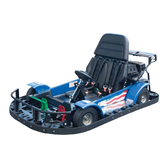
12-3 BODY MOUNTS - F-22 GO-KART The reinforced fi berglass body rests on rubber bumpers that support and isolate the body from the frame. Eye bolts are used to secure the hold-down straps. Bumpers are bolted to the mounting brackets and are easily replaced if damaged. - Page 198 12-4 BODY REMOVAL SCORPION & KING SCORPION: Unlatch the body latches. Remove the two 3/4” nuts that secure the body to the chassis. Lift the body off the chassis with the front of the body slightly higher than the rear to clear the steering wheel.
- Page 199 12-5 EAGLE /TALON SIDE PANELS/FENDERS OVERVIEW Double Eagle go-kart shown The Eagle/Talon go-kart utilizes the same frame as most other J&J go-karts. The panels and other fabricated steel parts are simple, bolt-on items. The side panels span between the frame spindle mounts and the roll bar/body mount. The formed plastic wing is rubber-mounted via special grommets in the mounting holes to “fl...
- Page 200 12-6 EAGLE /TALON SIDE PANELS/FENDERS THE FRONT FENDER: The front fender is mounted to the side panel with two 5/16” bolts above the spindle and two 1/4” bolts on the bottom lip of the side panel. THE REAR FENDER: The rear fender is mounted to the side panel Front fender with one 5/16”...
-
Page 201: Warning Decals
12-7 WARNING DECALS (TYPICAL LOCATIONS) Go-karts are terribly unforgiving of carelessness or neglect. To help avoid incidents and accidents, it is imperative that warning decals are legible and in place. The following outlines the typical locations of particular warning decals on bodied and non-bodied go-karts, as installed at the time of manufacture. - Page 202 12-8 WARNING! Go-karts have rotating parts. Can-Am & For your safety, longer hair Sidekick must be secured above the shoulder and any personal items (clothing, jewelry, etc) must be secured and contained within the seating area. Serious injury or death could occur! Sidewinder(s) DO NOT REMOVE THIS DECAL #1-60-0288 - 3.75”x5.0”...
- Page 203 12-9 TO HELP PREVENT INJURY OR DEATH All pads and guards must be maintained and in place during operation of this device. DO NOT REMOVE THIS DECAL #1-60-0388 This decal is located on the back side of all roll bars and also on the axle cover just below the brake access panel.
- Page 204 12-10 WARNING Keep Hands And Arms In Car At All Times. DO NOT REMOVE THIS DECAL #00980 #00180, gas powered go-karts only. ! WARNING Must meet posted height requirement. Shoes and shirt must be worn. All loose clothing must be secured. Hair longer than shoulder length must be secured above shoulder length.
- Page 205 12-11 DECAL REMOVAL AND INSTALLATION REMOVAL: Use a hot air gun to heat the decal (the heat is not for melting away the decal, but for heating the adhesive enough to removal the decal). Repeat until the decal is completely removed. Apply a small amount of WD-40 to a clean cloth (the cloth should be damp, but not soaked) and wipe away the glue on the fi...
-
Page 206: Body Seal
12-12 BODY SEAL OVERVIEW Seal Some fi berglass bodies are open in the seatback area to allow the body to be removed for service. The open area must be protected in case tied-back hair or loose clothing comes loose during the ride. These seals will help prevent long hair or loose clothing from entering the engine/drive axle area. - Page 207 13-1 Electric Go-Karts Frequent questions .............page 13.2 Throttle cable adjustment ..........page 13-29 Basic electrical troubleshooting ........page 13-4 Motor controller ..............page 13-32 Voltage drop test ..............page 13-7 Interconnect board ............page 13-36 Testing fuse ................page 13-8 Switch box ................page 13-44 Wire schematic ..............page 13-9 Switch box testing .............
- Page 208 13-2 Frequently Asked Questions About Electric Go-Karts HOW LONG CAN THE KART RUN BEFORE IT MUST BE RECHARGED? Due to variations in the track design, the length of time the kart can operate will diff er from track to track. One of the biggest issues to remember when setting the run times is to never allow the battery to run lower than 80% of a full charge.
- Page 209 13-3 HOW DO I TEST THE BATTERY PACK? The best way to test a battery is to test it with a load. This test can be performed a couple of diff erent ways. Using a voltage meter, attach the leads of the meter to the charging plug of the motor. Using the motor as the load, drive the kart and watch the meter.
- Page 210 13-4 IF THE SWITCH BOX HAS A PROBLEM, DO I NEED TO REPLACE IT? In many cases, when a switch box has a problem, it can be easily fi xed. The switches used are heavy-duty and should last a long time; often, when there is a problem, the cause is related to a loose or broken wire at the switch. CAN THE BUTTONS BE REPLACED? Yes, the red or black switch buttons can be replaced.
- Page 211 13-5 Basic Electrical Troubleshooting Whenever testing for power (voltage) fl ow in the circuit, the FIRST order of business is to establish and verify the test unit is functioning properly and has a solid ground. When possible, attach the ground lead of the tester directly to the ground post of the battery pack.
- Page 212 13-6 2) Everything has resistance. The wires, connectors, and switch contacts that make up a circuit all have some resistance and, as its name implies, resistance opposes (resists) current. In an undamaged, properly designed circuit, normal resistance is small enough that it doesn’t keep the load from working. UNWANTED RESISTANCE IN THE CIRCUIT REDUCES THE AMOUNT OF ELECTRICAL ENERGY DELIVERED TO THE LOAD.
-
Page 213: Voltage Drop Testing
13-7 Voltage Drop Testing The battery pack contains four 12-volt, deep-cycle batteries connected in series to produce a 48vdc “pack”. 4-gauge copper cables are used to connect the pack and furnish power through the relay/solenoid to the powered fuse and components. - Page 214 13-8 Testing A Fuse It is extremely important to understand that if a fuse looks good, it might not in fact be good! Fuses can appear to be fi ne and have a break in them so small that it cannot be seen by the naked eye. Therefore, it is important to check a fuse with an ohmmeter or a continuity tester instead of assuming that it is good.
- Page 215 13-9 4 Gauge Cable Schematic Battery Battery Battery Battery Sevcon Controller F2 A2+ Motor F1 A1+ SB-175 Charger Pickups Ground Ground Positive phone: 1-800-854-3140 | 1-503-304-8899 fax: 1-800-366-7505 | 1-503-304-1899 www.jjamusements.com...
-
Page 216: Battery Pack
13-10 Battery Pack General description .............page 13-10 Remove & replace ..............page 13-12 Testing ..................page 13-11 OVERVIEW The battery pack consists of four 12-volt batteries that are wired in series to achieve the required 48 volts. The batteries in the electric karts must have specifi c characteristics to be used in this application. They must fi rst be safe when impacts to the kart occur and the batteries are jarred around. -
Page 217: Battery Pack Testing
13-11 Battery Pack - Testing OPEN CIRCUIT VOLTAGE TEST - NO LOAD State of charge - 48vdc battery pack State of charge - Individual 12v battery % Charge Volts % Charge Volts 50.93 12.70 50.47 12.50 49.99 12.42 49.49 12.32 48.96 12.20 48.41... -
Page 218: Battery Pack Replacement
13-12 Battery Pack - Replacement Turn the kart off and remove the battery covers or kart body to access the batteries. WARNING Carefully remove the negative cable. Be sure to not allow the wrench to touch the positive and negative lugs of the battery at the same time. -
Page 219: Fuse
13-13 FUSE OVERVIEW The 300-amp main fuse keeps power surges or short circuits from destroying the electronic components. All power from the battery pack or to the pack from the charger goes through this fuse. phone: 1-800-854-3140 | 1-503-304-8899 fax: 1-800-366-7505 | 1-503-304-1899 www.jjamusements.com... - Page 220 13-14 Fuse - Removal/Replacement Be sure the kart is in the “off ” position by pushing the red “stop” button down. NOTE: Always disconnect the battery pack’s negative terminal before removing the electronics cover; see page 13-12 for negative terminal removal. Remove the electronic cover by removing the 4 bolts holding the cover.
- Page 221 13-15 Using a voltage/ohm tester, check the continuity of the fuse. To remove the fuse, loosen the nuts on each end. With the nuts loosened, the fuse can be removed by lifting the right side, then sliding the fuse out of the holder.
- Page 222 13-16 Install the new fuse in the reverse manner that the old fuse was removed. Specifi cations and prices subject to change without notice. Download latest update to this manual on-line.
-
Page 223: Relay
13-17 Relay OVERVIEW The J&J electric go-kart uses this device as a safety-related item to remove all power to the motor when the throttle is at the rest position for a given period of time (approximately 10 seconds). The “seat switch” circuit of the controller is programmed as part of the J&J profi... - Page 224 13-18 Relay - Removal/Replacement NOTE: Always disconnect the battery pack negative terminal before removing the electronics cover (see page 13-12 for negative terminal removal). Remove the electronic cover. Locate the relay on the heat sink board. Heat sink board Relay Remove the two large cables from the posts on the top of the relay.
- Page 225 13-19 Remove the two smaller wires from the lower posts on the relay. Loosen one of the button-head screws holding the relay to the heat sink panel. Remove the opposite button-head screw completely. Slide the relay off of the remaining screw to completely remove the relay.
-
Page 226: Linear Throttle Potentiometer
13-20 Linear Throttle Potentiometer Simply put, the linear throttle potentiometer changes the movement of the “go” pedal into an electronic signal and sends that information to the controller. The farther the pedal is depressed, the faster the kart will travel. The linear throttle potentiometer plugs into the interconnect board with a Molex-style plug. - Page 227 13-21 Linear Throttle Potentiometer - Removal/Replacement Remove the negative cable from the left rear battery. NOTE: Always remove the negative cable fi rst and attach it last when removing or replacing any battery or performing any electric service. Remove the electronic cover. Remove the axle guard to allow better access to the linear throttle potentiometer.
- Page 228 13-22 Locate the linear throttle potentiometer. Remove the 4 socket head retaining bolts. The throttle plate can now be removed to allow better access (do not pull excessively on the throttle inner cable or housing). Specifi cations and prices subject to change without notice. Download latest update to this manual on-line.
- Page 229 13-23 Remove the throttle cable from the throttle arm. Remove the throttle arm from the linear throttle potentiometer. Using two wrenches, loosen the throttle clevis pin while being sure not to move the jam nut. phone: 1-800-854-3140 | 1-503-304-8899 fax: 1-800-366-7505 | 1-503-304-1899 www.jjamusements.com...
- Page 230 13-24 Count the number of threads showing where the clevis pin was; you will need to know this when installing the clevis pin onto a new linear throttle potentiometer. Remove the two hex-head pan screws; be sure to hold the lock nut on the back side. Install the new linear throttle controller;...
- Page 231 13-25 Be sure the jam nut has the same number of threads showing that you counted before removing. Install throttle clevis pin hand-tight. Move the throttle arm into position in the clevis pin, then tighten the jam nut tightly; be sure the arm moves freely back and forth.
- Page 232 13-26 Adjusted properly, the hole in the throttle cable end should line up with the hole in the throttle cable arm. With the cable connected, check the movement. Be sure the cable and arm move smoothly and go to a complete rest with no tension.
- Page 233 13-27 Throttle Cable Removal/Replacement Loosen the jam nut closest to the throttle arm. Loosen the nut holding the cable in place on the bracket. Remove the nut holding the cable clevis pin to the throttle arm. phone: 1-800-854-3140 | 1-503-304-8899 fax: 1-800-366-7505 | 1-503-304-1899 www.jjamusements.com...
- Page 234 13-28 Slide the cable adjuster housing back through the cable mount. Slide the wire through the slit in the cable mount. CABLE CARE Part# Description Price 00122 Cable Lubricator Luber $20.74 Protects sleeved cables and prolongs cable life 3-60-0029 Cable Life (Lube Only) $11.99 Specifi...
-
Page 235: Throttle Cable Adjustment
13-29 Throttle Cable Adjustment Throttle arm Cable clevis end Throttle inner cable Cable housing end Cable housing The throttle cable may need to be adjusted to either speed up or slow down the top speed of the kart. The picture above identifi es the names of the parts involved in adjusting the throttle cable. NOTE: This is a critical adjustment, as the overall travel of the linear actuator rod dictates the performance throughout the range of the kart. - Page 236 13-30 Throttle cable adjustment is setting the amount of “throw” or “travel” the cable pulls on the throttle arm. Throttle arm cable travel The throttle cable housing end fi tting is threaded to allow for adjustment. This adjustment can increase or decrease the amount the cable moves the throttle arm.
- Page 237 13-31 On electric karts, when the cable is installed at the factory, both jam nuts are on the outside of the throttle cable bracket. Both nuts will need to be removed, then one threaded on the cable housing end prior to being re- installed to change the adjustment.
-
Page 238: Motor Controller
13-32 Motor Controller This is the controller: the most technical part of the kart. The controller is a completely sealed unit containing power and logic circuitry; it is FLASH-microprocessor-based, enabling fi eld re-programming, and off ering numerous user set-up options. The controller contains a triple-fail-safe system to provide a high level of safety. If the diagnostic LED fl ashes, or is not illuminated, the safety circuit may have been tripped and the kart may not operate. - Page 239 13-33 Motor Controller Removal/Replacement Remove the negative cable from the left rear battery. NOTE: Always remove the negative cable fi rst and attach it last when removing or replacing any battery, or performing any electric service. Remove the electronic cover. Locate the controller and unplug the interconnect board cable.
- Page 240 13-34 Remove all of the remaining cables to the controller. Remove the 2 bottom Allen-head bolts holding the controller to the heat sink board, and one of the top Allen-head bolts. Remove the remaining top bolt; be sure to support the controller as you are removing the last bolt.
- Page 241 13-35 Before installing the new controller, be sure to put a fi lm of thermal paste (J&J# 2-70-0112, dielectric grease) on the back to help with heat transfer from the controller to the board then follow the steps above in reverse (see the wiring diagram below for controller wiring).
-
Page 242: Interconnect Board
13-36 Interconnect Board External power Throttle input connection connection Brake pressure switch connection Peripheral input connection, i.e. remote shut-down Relay cable Communications connection cable connection to controller On/off switch box connection The interconnect board’s function is actually quite simple: it takes the place of wires and terminal blocks to send the inputs to the controller. - Page 243 13-37 Many of the components previously listed connect to the interconnect board. Each input location is labeled (as seen in the picture above), however, it is covered by a protective shield when it is on the kart, making it hard to see the labels. Here is a listing of the connection points and what goes where: J1 - Low-voltage power (+) output used to power the remote speed control system.
- Page 244 13-38 Interconnect Board - Removal Remove the negative cable from the left rear battery. NOTE: Always remove the negative cable fi rst and attach it last when removing or replacing any battery, or performing any electric service. Remove the electronic cover. Locate the interconnect board.
- Page 245 13-39 Carefully remove the throttle input plug from the interconnect board. Unplug the communication cable (“interconnect board cable”). Unplug the brake pressure switch cable. phone: 1-800-854-3140 | 1-503-304-8899 fax: 1-800-366-7505 | 1-503-304-1899 www.jjamusements.com...
- Page 246 13-40 Unplug the on/off switch box cable. Unplug the relay cable. Remove any wires connected to an external power point. Specifi cations and prices subject to change without notice. Download latest update to this manual on-line.
- Page 247 13-41 Remove any wires connected to the peripheral (TS1) input connection points. Mark the color and connection location for reassembly. Loosen the 4 pan-head screws that hold the interconnect board to the heat sink panel. Carefully remove the interconnect board. Be sure to leave the pan-head screws in place;...
- Page 248 13-42 Place the board on a fl at surface (it is a good idea to use a towel or cloth underneath while you are working on it). Carefully remove the pan-head screws holding the interconnect board guard to the board. To install a new interconnect board, reverse the steps above.
- Page 249 13-43 NOTE: Be careful when plugging the throttle input plug into the interconnect board (C2). Since the connection is on the corner of the board, it can fl ex the board into the heat sink plate, causing a short in the board, or causing traces to crack due to the fl...
-
Page 250: Switch Box
13-44 Switch Box OVERVIEW This is the on/off button and the forward/reverse switch. This button and switch go through the interconnect board to control power to the kart and put it in a forward or reverse direction. WHEN THE REMOTE SPEED CONTROL SYSTEM IS USED, THE KART WILL NOT GO INTO A REVERSE SPEED UNTIL THE KART IS PUT INTO THE “SLOW”... -
Page 251: Switch Box Testing
13-45 Switch Box Testing Remove the negative cable from the battery pack (see page 13-12). Remove electric component cover. If you suspect a problem in the switch box, it can be easily tested by using a unit that is known to function. - Page 252 13-46 Reconnect the battery ground removed earlier. Using the alternate switch box, turn the kart on. If the problem was inside the switch box, the kart should turn on and the light on the controller should be solid green. Specifi cations and prices subject to change without notice. Download latest update to this manual on-line.
- Page 253 13-47 Switch Box Removal/Replacement To correct the problem created by a faulty switch box, the box can be replaced, however; it is a good idea to check the connections inside the box, as a loose wire can easily be repaired. FOLLOW THE STEPS BELOW.
- Page 254 13-48 Brake Pressure Switch OVERVIEW The brake pressure switch is designed to drop the power out from the motor when the brake pedal is depressed. If this circuit were not in place, the kart’s motor would fi ght against the brake system, causing extreme amp-draw situations. Specifi...
- Page 255 13-49 Brake Pressure Switch Testing/Removal Remove the axle guard or inspection cover to gain access to the pressure switch. The brake pressure switch is set to normally closed when the brake pedal is not being depressed. To test, use a multi meter set to test continuity;...
- Page 256 13-50 If the kart does not operate and you suspect a faulty switch, you can bypass the switch by using a jumper from one tab to the other. If the kart now functions properly, then the switch must be replaced. Coat the threads on the new switch lightly with pipe thread sealer.
- Page 257 13-51 Remove and replace the existing pressure switch and re-connect the wires removed in the step above. There is no continuity, so the wires can go on either tab. Bleed the brakes to remove the air from the brake lines. BLEED YOUR BRAKES WITH EASE.
-
Page 258: Schematic - 4-Gauge Cable With Voltage Battery Tester
13-52 Schematic - 4- Gauge Cable With Votage Battery Tester Front of go kart NEGATIVE POSITIVE LEFT RIGHT FRONT FRONT POSITIVE NEGATIVE POSITIVE NEGATIVE LEFT RIGHT REAR REAR NEGATIVE POSITIVE ELECTRIC PANEL Sevcon Controller SB-175 F2 A2+ Motor F1 A1+ VOLT METER LEFT FRONT RIGHT FRONT... -
Page 259: Schematic - Led Lighting
13-53 Schematic - Led Lighting Front of go kart Front o kart HEAD LIGHT HEAD LIGHT NEGATIVE TIVE POSITIVE LEFT RIGHT FRONT FRONT NEGATIVE POSITIVE POSITIVE LEFT RIGHT REAR REAR NEGATIVE SWITCH 1-60-0347 BRAKE SWITCH ON CALIPER OPTIONAL LIGHT BRAKE LIGHT OUTPUTS phone: 1-800-854-3140 | 1-503-304-8899 fax: 1-800-366-7505 | 1-503-304-1899 www.jjamusements.com... -
Page 260: Schematic - Interconnect Board With Kartrol
13-54 Schematic - Interconnect Board With Kartrol This is the remote shut-down receiver and wire harness. The remote shut- 1-60-9027 without 1-60-9029 with pit pit loop detector loop detector down receiver and wire harness receives signals from the transmitters and changes those into electronic signals to put the kart into stop, slow, medium, and “go”... -
Page 261: Schematic - Interconnect Board Without Kartrol
13-55 Schematic - Interconnect Board Without Kartrol RELAY ON/OFF SWITCH Sevcon Controller CHARGE INDICATOR MOTOR LIGHT CONTROLLER BATT + BATT - INTERCONNECT BOARD 1-15-0105R3 REV 1 White Charger Pickups BRAKE SWITCH LINEAR THROTTLE POTENTIOMETER Red wire to this plug. Black SB-175 SB-175 SB-175... - Page 262 13-56 Testing Flash Codes (Pc-Pak) This is the Sevcon PC Pak. This is not part of the kart: it is a tool to help assist in troubleshooting, as well as to allow changes to be made to the kart profi le. The cable comes with software for a PC system. The plug uses a serial port, which most new PC’s no longer use.
- Page 263 13-57 Testing Flash Codes Open your control panel and fi nd the icon for Device Manager; open the Device Manager. Find the icon labeled “Ports (COM & LPT)”; click the icon to see the drop-down menu. With the drop-down open, you will see the COM port location.
- Page 264 13-58 With the program open, click on the “Tools” tab on the top bar; it will open up a box in the middle of the screen. The fi rst tab of the box is marked “Connection”; click that tab. The connection box will have a drop-down for the diff...
- Page 265 13-59 To save a copy of the workin g profi le, follow these steps: With the cable connected to the controller and the profi le open, click on the “File” tab on the top bar, then choose “Save” from the drop-down menu. This will open another box asking which “Node”...
- Page 266 13-60 Controller Flash Faults SYMPTOM: NO LIGHT = NO POWER TO CONTROLLER Check the kart on/off switch to make sure it is in the “on” position. Check the batteries (see pg 13-11). If the batteries test ok, check the power and ground leads. The main ground (negative lead) from the battery pack is attached to the (B-) lug on the Sevcon controller.
- Page 267 13-61 You will need a working profi le to install into the non-functioning controller; follow the step on page 13-59, if you do not have a copy of a working profi le. Be sure to copy the profi le from a kart that is known to work. Connect the PC Pak cable to the non-working controller.
- Page 268 13-62 Find the saved profi le and choose “Open.” Click the “Next” button on the bottom of the box. The box will change to “Check the node compatibility;” click the “Next” button again. Specifi cations and prices subject to change without notice. Download latest update to this manual on-line.
- Page 269 13-63 The next box will be the Rapid Download Wizard. Click the large “Download” button in the middle of the box. When the download is complete, a dialog box will open stating this. Click the “Ok” button. The “Rapid Download” box will reappear; click the “Finish”...
- Page 270 13-64 SYMPTOM: 2 FLASHES = ILLEGAL START CONDITION. This code relates to a problem with peripheral inputs during start-up. The controller is very much like any other personal computer. During start-up, it does a check of all the outside equipment (i.e. the throttle, brake pressure switch, remote shut down (if used) etc..
- Page 271 13-65 If the batteries are over standard voltage (64 volts or higher), that may be a sign of a larger problem. The charging system utilizes a smart charger; it reads the battery voltage and charges according to how low the level of voltage is in the battery pack.
- Page 272 13-66 SYMPTOM: 8 FLASHES= CONTROLLER OVER TEMPERATURE. This code is generated when the controller is overheated. This can result from a few diff erent possible issues. The most common reason for the controller being overheated is directly related to the heavy motor cables. If there is a bad crimp or wire failure, they can create heat which travels back to the controller.
- Page 273 13-67 Floor-Charging System The fl oor-charging contact system is a mechanical part of the electric kart charging system. Because of the importance of making sure the kart is being recharged properly, it should be inspected for proper operation. Be sure both contacts are in good condition, and they slide both up and down freely in the holder.
-
Page 274: Carburetor Check Sheet
INDEX Index Removal/Installation 12-11 Keeper Disc brake specifi cation 7-2 Installation 8-20 Drum brakes Removal 8-19 Adjustment 7-27 Ackerman eff ect 4-10 Brake shoes 7-21, 7-22 Anti vibration grabber plate 8-3 Overview 7-19 Linear throttle potentiometer 13-20 Parts identifi cation 7-20 Lug nuts Disc-lock 1-3 Battery... - Page 275 Gas powered go-karts 0-9 Setup Go-kart 0-24 Side panel 12-5, 12-6 Specifi cations Electric powered double seat go-karts 0-3 Electric powered rookie go-karts 0-6 Electric powered single seat go-karts 0-4 Gas powered rookie go-karts 0-5 Gas powered single seat go-karts 0-2 Spherical washers 7-3 Spindle 3-1 Assembly 3-9...
Need help?
Do you have a question about the KING SCORPION and is the answer not in the manual?
Questions and answers