Table of Contents
Advertisement
1.
Type identification ........................................................................................................................... 2
1.1
Nameplate ........................................................................................................................................................... 2
1.2
Type key .............................................................................................................................................................. 3
2.
Tightening torques and lubricants................................................................................................. 4
3.
Service tools .................................................................................................................................... 5
3.1
Special tools ........................................................................................................................................................ 5
3.2
Standard tools...................................................................................................................................................... 6
3.3
Torque tools......................................................................................................................................................... 6
4.
Dismantling and assembly ............................................................................................................. 7
4.1
General ................................................................................................................................................................ 7
4.2
Replacement of motor ......................................................................................................................................... 8
4.3
Replacement of shaft seal ................................................................................................................................... 9
4.4
Dismantling and assembly of pump main parts ................................................................................................. 10
4.5
Dismantling and assembly of chamber stack .................................................................................................... 11
4.6
Dismantling and assembly of base and pump head .......................................................................................... 12
4.7
Checking and replacing parts ............................................................................................................................ 13
5.
Order of assembly for chambers and impellers ......................................................................... 14
5.1
CRE 1 and CRE 3.............................................................................................................................................. 14
5.2
CRE 5 ................................................................................................................................................................ 15
GB
96547191 0407
Service instructions
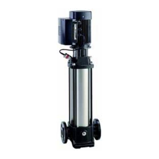
CRE 1, CRE 3 and CRE 5
Model A
50/60 Hz
1/3~
1 / 15
Advertisement
Table of Contents

Summary of Contents for Grundfos A Series
-
Page 1: Table Of Contents
Service instructions CRE 1, CRE 3 and CRE 5 Model A 50/60 Hz 1/3~ Type identification ........................... 2 Nameplate ................................2 Type key ................................3 Tightening torques and lubricants....................4 Service tools ............................ 5 Special tools ................................ 5 Standard tools..............................6 Torque tools................................. -
Page 2: Type Identification
1. Type identification This section shows the type key, the nameplate and the codes that can appear in the variant code. Note: As codes can be combined, a code position may contain more than one letter. 1.1 Nameplate CRE5-10 AN-FGJ-A-E-HUB Type Model A96459132P10117... -
Page 3: Type Key
1.2 Type key Example XXXX Type range Rated flow rate in m³/h Number of stages Code for pump version A = Basic version G = Pump for booster system N = Pump with pressure sensor U = NEMA version Code for pipe connection A = Oval flange FGJ = DIN, ANSI and JIS flange Code for pump materials... -
Page 4: Tightening Torques And Lubricants
2. Tightening torques and lubricants Pos. Description Number Dim. Torque [Nm] Lubricant Screw Hexagon socket head screw THREAD-EZE Air vent screw (spindle) ½" (M8) 35 (3) Plug ½" Soapy water Drain plug with bypass valve (spindle) ½" (M10) 35 (5) Staybolt THREAD-EZE Hexagon head screw... -
Page 5: Service Tools
3. Service tools 3.1 Special tools Pos. Description For pos. Suppl. information Part no. Shaft holder for assembly SV0040 Tubular box spanner for shaft seal SV2007 Puller SV0239 Circlip pliers (not used for CR) SV2014 Tool for outer sleeve V7170478 Tool for corrugated spring V7170227 Tool for O-ring... -
Page 6: Standard Tools
3.2 Standard tools Pos. Description Bit no. For pos. Suppl. information Part no. Bit holder 1/4" SV2011 1/4" M6 - 5 mm 1/4" Bits kit SV2010 M8 - 6 mm 1/4" M10 - 8 mm 1/4" Hexagon bit 113-H-M M5 - 2.5 mm 1/4"... -
Page 7: Dismantling And Assembly
4. Dismantling and assembly 4.1 General If it is necessary to dismantle the pump, either because it is choked or damaged, please follow the instructions in the following sections. Position numbers of parts (digits) refer to exploded views, sectional drawings and parts lists; position numbers of tools (letters) refer to 3. -
Page 8: Replacement Of Motor
4.2 Replacement of motor 4.2.1 Dismantling 1. Disconnect the pressure sensor, if fitted, from the terminal box of the motor. See fig. 1. MGE 71, MGE 80 MGE 90, MGE 100, MGE 112, MGE 132 Black Brown (8) Brown Black (7) Fig. -
Page 9: Replacement Of Shaft Seal
4.3 Replacement of shaft seal 4.3.1 Dismantling 1. Remove the motor and the coupling. See 4.2.1 Dismantling. 2. Slacken the three screws (pos. 113) by approx. a ¼ of a turn so that the shaft seal is just free of the shaft. 3. -
Page 10: Dismantling And Assembly Of Pump Main Parts
4.4 Dismantling and assembly of pump main parts 4.4.1 Dismantling 1. Remove the shaft seal. See 4.3.1 Dismantling. 2. Remove the pressure sensor, if fitted, from the pump head (pos. 2). 3. Slacken and remove the screws (pos. 36) together with the washers (pos. 66a). 4. -
Page 11: Dismantling And Assembly Of Chamber Stack
4.5 Dismantling and assembly of chamber stack 4.5.1 Dismantling 1. Remove the chamber stack. See 4.4.1 Dismantling. 2. Place the shaft holder (pos. A) in a vice, but do not tighten the vice. 3. Fit the shaft pin (pos. 10) into the shaft pin hole and place the chamber stack in the shaft holder (pos. A). See fig. -
Page 12: Dismantling And Assembly Of Base And Pump Head
4.6 Dismantling and assembly of base and pump head 4.6.1 Dismantling of base 1. Remove the staybolts (pos. 26) from the base (pos. 6). 2. Remove flange connection, if any: Oval flange: Remove the screws (pos. 35), the flange (pos. 12) and the gasket (pos. 39). 3. -
Page 13: Checking And Replacing Parts
4.7 Checking and replacing parts Check Replace Impeller Neck ring/retainer for neck ring • Check whether it is necessary to replace the impeller 1. Prise the retainer for neck ring (pos. 65) up and free due to friction between the neck ring and the impeller of the chamber using the puller (pos. -
Page 14: Order Of Assembly For Chambers And Impellers
5. Order of assembly for chambers and impellers 1. Determine the pump type (CRE 1, CRE 3 or CRE 5) and the stage variant. Find the pump in the relevant stage survey table. 2. Find the components of each stage in the symbol survey. 5.1 CRE 1 and CRE 3 Stage survey CR / CRI / CRN 1 &... -
Page 15: Cre 5
5.2 CRE 5 Stage survey CR / CRI / CRN 5 - 16 18 20 Symbol survey 15 / 15...


Need help?
Do you have a question about the A Series and is the answer not in the manual?
Questions and answers