
Related Manuals for INIM Electronics Sol-P


Summary of Contents for INIM Electronics Sol-P
- Page 1 Installation manual EN 50131-1 EN 50131-3 EN 50131-6 EN 50131-10 EN 50136-1 EN 50136-2 EN 50130-4 EN 50130-5 CEB T031 Installation manual Anti-intrusion control panels and security systems...
-
Page 2: Warranty
Contact Our authorized dealer, or visit our website for further information regarding this warranty. Limited INIM Electronics s.r.l. shall not be liable to the purchaser or any other person for damage warranty arising from improper storage, handling or use of this product. -
Page 3: Table Of Contents
Installation manual Table of contents Warranty ..........2 Limited warranty . - Page 4 Anti-intrusion control panels...
-
Page 5: About This Manual
Installation manual About this manual MANUAL CODE DCMIINE0SOLE REVISION 1.00 Terminology CONTROL PANEL, SYSTEM, DEVICE The main control unit or any constituent part of the Sol intrusion control system. LEFT, RIGHT, BEHIND, ABOVE, BELOW Directions as seen by the operator when directly in front of the mounted device. QUALIFIED PERSONNEL Persons whose training, expertise and knowledge of the products and laws regarding security... -
Page 6: Chapter 1 General Information
The persons authorized by the manufacturer to repair or replace the parts of this system have authorization to work only on devices marketed by INIM Electronics. Patented technologies The Sol series of control panels has the following patented technologies. -
Page 7: Operator Qualifications
Installation manual It also contains the instructions for commissioning, maintenance and troubleshooting. SOFTWARE PROGRAM The Sol/STUDIO software manual contains the description of the software and the instructions for its installation and use. It is the responsibility of the person who programs the Sol system to adhere to the instructions and to have complete knowledge of the software in order to work swiftly and properly through the configuration and programming procedures. -
Page 8: The Control Panel And Peripherals
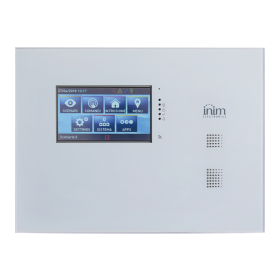
Anti-intrusion control panels The control panel and peripherals Chapter Sol control panels 2-1-1 Inside the box Inside the box you will find: • Metal enclosure containing the motherboard and wired power supply • User's Manual • Quick guide to installation and programming •... - Page 9 The following table shows the maximum number of devices supported by the various control panel models. Table 2-3: Control panel - main features Sol control panel models Sol-S Sol-G Sol-P built-in touch- screen built-in LCD Graphic display (192x64) (4.3", 480x272, 65.000 colours)
- Page 10 Anti-intrusion control panels Table 2-4: Sol control panels - external Graphic display Keypad Signalling LEDs Microphone Proximity reader Buzzer/Speaker Sounder-flasher Brightness sensor Control panel closure screws Cable entry Mounting screw hole Hole for the anti-open- ing/anti-dislodgement protection The control panel and peripherals...
- Page 11 Activity LED Green power LED CHARGE Red battery-charge status LED Yellow activity on BUS LED Blue activity LED Open-panel/dislodgement tamper micros- witch Table 2-6: Sol-P - motherboard Mother board PCB / display RESET System reset button CALIBRATE- Forced calibration button TOUCH...
- Page 12 AC mains voltage and the battery. TOUCH-SCREEN CALIBRATION If the touch screen of the Sol-P does not respond properly to taps, you must implement the forced calibration process. This process is initialized by simply pressing and holding the respective button for 7 seconds (Table 2-6: Sol-P - motherboard, D).
-
Page 13: Peripherals On I-Bus
• Readers (nBy/S and nBy/X) • Transceiver (Air2-BS200) The intellectual property rights regarding the electrical, structural and protocol features of the BUS are the sole property of INIM Electronics s.r.l. The I-BUS is not a RS485 differential BUS. ATTENTION! The connectible peripherals must have firmware versions higher than or equal to 6.00. - Page 14 Anti-intrusion control panels 2-2-1 Readers - nBy/S and nBy/X Table 2-9: nBy - electrical and mechanical features Model nBy/S nBy/X Voltage from 9 to 16V Typical current draw 40mA 35mA Temperature from -25° to +70° C from -10° to +40° C Maximum humidity 93% (without condensation) 75% (without condensation)
-
Page 15: Accessory Modules For Connectivity
Installation manual Accessory modules for connectivity Sol control panels allow the use of accessory modules in order to increase the already available functions. These are modules, for installation directly inside the control panel enclosure via the allocated connectors, which interface with the control panel in addition to the on-board USB port, via other communication channels. - Page 16 Anti-intrusion control panels Table 2-14: 3G - description of parts Antenna SIM card housing (non included) GSM communication LED (red) BUS communication LED (yellow) Connection LED (green) Control panel connector (on the under side) 2-3-2 Sol-LAN/S and Sol-WIFI, LAN interfaces Sol control panels provide the possibility to connect to LAN networks and to the Internet via the optional Sol-LAN/S modules for connections to Ethernet networks, or via Sol-WIFI for WiFi connections.
- Page 17 Installation manual 2-3-3 Sol-PSTN, PSTN communicator module The use of an optional Sol-PSTN module allows you to connect the PSTN line (Public Switched Telephone Network line) to the control panel and to activate all the functions that use this line: •...
-
Page 18: Chapter 3 Wireless Systems
Anti-intrusion control panels Wireless systems Chapter All Sol control panels have integrated transceivers and, therefore, can manage the Air-2 two- way wireless system. Table 3-1: Technical specifications of Air2 system range 868.0 - 868.6MHz Operating frequency selectable channels 868.1, 868.3, 868.5MHz RF output power 25mW e.r.p. -
Page 19: Air2 Devices
Installation manual Air2 devices 3-1-1 Air2 remote-control key The Air2 remote-control key has 4 buttons which can be programmed from the control panel. EN 50131-1 EN 50131-5-3 Table 3-2: Technical features of Air2 remote-control keys EN 50130-4 EN 50130-5 Models KF100 Pebble Ergo... - Page 20 Anti-intrusion control panels ROLLING-CODE AUTHENTICATION A further guarantee of security regarding the signal transmissions from Air2 remote-controls is provided by the use of a rolling code algorithm. This allows the transceiver module to check the validity of each wireless keyfob transmission. In the event of irregular wireless activity, denial-of-request will be signalled by an audible error signal (“bop”).
- Page 21 Installation manual SHOCK DETECTION Signalling of shock waves is achieved through a tri-axial vibration sensor. The vibration sensibility can be set either from a keypad or via the programming software application. TILT DETECTION Signalling of tilting (angle change) is achieved through tri-axial tilt sensing. The tilt-variation value (angle) can be set in relation to the standby position, which is saved to the memory during the reset-after -alarm phase.
- Page 22 Anti-intrusion control panels The following table indicates the operating distances of the magnet in accordance with the side used and the angles shown in the figure (these values have been calculated by positioning the magnet in contact with the device, except for the angle y-, and with the highest part of the contact cover aligned with that of the magnet cover): Table 3-11: Distance between magnet and contact (mm) Contact long side...
- Page 23 Installation manual Table 3-13: Description of Air2-FD100 parts Detector LED red/yellow/green Optical chamber Battery Tamper microswitch ENROLL microswitch Base Mounting screw hole The tricolour LED (360° visibility) indicates the detector status. • Green - one flash every 15 seconds: detector operating properly. •...
-
Page 24: Chapter 4 Installation
Anti-intrusion control panels Installation Chapter Installing the control panel 4-1-1 Wall-mounting The control panel should be installed indoors in a place adapted to its intended use and that also allows easy access to it via keypad or reader. For optimal functioning of the wireless system, the control panel must be placed in a position that is central to the detectors and range of use of the remote-control devices. - Page 25 Installation manual 4-1-2 Connecting the Mains power supply The control panel must be powered through a separate line coming from the Mains box. The line must be protected by a safety-standards compliant circuit breaker (trip switch). The circuit breaker (trip switch) must be located externally to the apparatus and should be easily accessible.
- Page 26 Anti-intrusion control panels If the battery does not result efficient, that is, the control panel detects an internal resistance superior to 1 Ohm, the system will generate a “Low Battery” event which will clear when the Ongoing faults resistance drops below 900 mOhm. Low battery This fault will be signalled on the yellow LED on the keypads.
-
Page 27: Installing Peripherals
Installation manual To close the control panel, work carefully through the previously mentioned steps in reverse order. 1. Exit maintenance mode. 2. Replace the frontplate screws. Via keypad 3. Exit the Installer menu. Note On exiting the Installer menu with the control panel still open, the system panel will not generate an “Open-panel”... - Page 28 Anti-intrusion control panels 4-2-2 Installing nBy/S readers The wall-mount nBy/S reader is suitable for indoor and outdoor installation. Insert the two anchor screws (included) into the two screw locations on the back of the plastic enclosure. Table 4-3: nBy/S installation Cover Silicone seal Back...
-
Page 29: Connecting And Balancing Alarm Detectors
Installation manual compressed) and connect one end of the 6k8 resistor to it [D]. Connect the other end of the resistance to the wire which is connected to the 24h input terminal. 5. Install the microswitch as shown in the previous figure, so that the switch lever is com- pressed. - Page 30 Anti-intrusion control panels 4-3-2 Single balancing Single zones can discriminate 3 conditions on the entire terminal: • standby • alarm • tamper (short-circuit) For each of these, the control panel reads different resistance values on the terminal, expressed below in Ohm. Zone Tamper +12V GND...
-
Page 31: Connecting And Balancing Roller Blind/Shock Sensors
Installation manual 4-3-5 Double Zone balancing with EOL Double zones with EOL resistors can discriminate 6 conditions on the entire terminal: • stand-by on both zones • alarm on zone 1 and standby on zone 2 • alarm on zone 2 and standby on zone 1 •... -
Page 32: Learn Zone Balancing
Anti-intrusion control panels 4-4-2 Single balancing (N.C. with EOL) In this case, the discriminated conditions are: • standby • alarm • tamper (wire cutting) • tamper (short-circuit) For each of these, the control panel reads different resistance values on the terminal, expressed below in Ohm. -
Page 33: Installing Optional Modules And Boards
Installation manual Control panel Control External Self-powered power sounder-flasher supply 13.8V Generic device Generic Indoor load 12V sounder- +12V GND Installing optional modules and boards 4-7-1 Installing internal modules The installation of Sol-PSTN, Sol-3G and Sol-LAN/S optional connectivity modules can be achieved using the connectors integrated into the PCB board and hooks on the back of the control panel enclosure. -
Page 34: Connecting The Land-Line (Pstn)
Anti-intrusion control panels 4-7-2 Installing optional internal boards The installation of Sol-WIFI and SmartLogos30M optional boards can be achieved via the connectors integrated into the PCB. This operation must be carried out when the mains power supply and battery are disconnected: 1. -
Page 35: Installing Wireless Devices
Installation manual Installing wireless devices 4-9-1 Installing the Air2 remote-control key The Air2 requires enrolling only. If it becomes necessary to replace the rubber button cover or battery, work through the following steps. 1. Remove the securing screw on the back of the keyfob and open the device. 2. - Page 36 Anti-intrusion control panels 4-9-4 Connecting Air2-MC300 wireless detectors The two terminals, T1 or T2, on the Air2-MC300 magnetic contact are configurable as either Air2-MC300 input or open-collector output. Configuring the terminals as inputs allows management of standard zone balancing (N.O., N.C., single balancing, double balancing) and also direct interfacing with roller-blind and shock Power supply...
- Page 37 Installation manual CONTROL PANEL REGISTERED TO INIM CLOUD The last section of the guided procedure provides the SEND button that sends all the acquired data to the Sol control panel via Inim Cloud. CONTROL PANEL NOT REGISTERED TO INIM CLOUD The last section of the guided procedure provides the SHOW button that displays a QR code on the screen, for use during the wireless device enrollment phase via the Sol/STUDIO software.
- Page 38 Anti-intrusion control panels Installation...
-
Page 39: Weee
Installation manual WEEE Informative notice regarding the disposal of electrical and electronic equipment (applicable in countries with differentiated waste collection systems) The crossed-out bin symbol on the equipment or on its packaging indicates that the product must be disposed of correctly at the end of its working life and should never be disposed of together with general household waste. - Page 40 Anti-intrusion control panels ISO 9001 Quality Management certified by BSI with certificate number FM530352 Centobuchi, via Dei Lavoratori 10 63076 Monteprandone (AP), Italy Tel. +39 0735 705007 _ Fax +39 0735 704912 info@inim.biz _ www.inim.biz DCMIINE0SOLE-100-201908...
Need help?
Do you have a question about the Sol-P and is the answer not in the manual?
Questions and answers