
Related Manuals for INIM Electronics Praesidia


Summary of Contents for INIM Electronics Praesidia
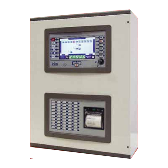
- Page 1 Configuration manual EN 54-2 EN 54-4 EN 54-21 EN 12094-1 cert. N.991K 0832 0832-CPR-F1342 PRAESIDIA Configuration manual FIRE DETECTION AND EXTINGUISHANT SYSTEM...
-
Page 2: Warranty
INIM Electronics s.r.l. (Seller, Our, Us) warrants the original purchaser that this product shall be free from defects in materials and workmanship under normal use for a period of 24 months. As INIM Electronics s.r.l. does not install this product directly, and due to the possibility that it may be used with other equipment not approved by Us; INIM Electronics s.r.l. -
Page 3: Table Of Contents
Configuration manual Table of contents Warranty.......................... 2 Limited warranty......................2 Copyright........................2 European directive compliance ................2 Table of contents ......................3 General information ....................5 Details of Manufacturer ........................5 Supplied Documentation .......................5 About this manual ..........................5 Description of the configuration and programming procedures ........6 Configuration ........................ - Page 4 Fire detection and extinguishant system Table of contents...
-
Page 5: General Information
INIM Electronics brand devices only. Supplied Documentation Praesidia User's Manual: contains the identification of the parts on the front plate and the end-user operating instructions for use. Praesidia216 Istallation Manual: contains the technical specifications of the Praesidia216 and the mounting, installation and wiring instructions. -
Page 6: Description Of The Configuration And Programming Procedures
Following is a flow chart which summarizes the operations to be carried out during the installation and commissioning phases of the Praesidia system and indications regarding the manuals to refer to for each operation. Installation and cabling (refer to the Installation Manual) 2. -
Page 7: Configuration
Chapter 2 Configuration Once the installation and cabling procedures have been completed (refer to the Installation Manual of the Praesidia system) the system is ready for the initializing phase. On first startup it will be necessary to select the system language (see paragraph 2.10). -
Page 8: Access To Programming
Fire detection and extinguishant system Access to programming In order to access the programming session of the Praesidia control panel, it is necessary to work through the following procedure: Insert the programming jumper on the back of the FPMCPU module (see opposite, [D]). -
Page 9: Addressing Ifm And Fpm Modules
Configuration manual Internal layout of the selected cabinet Internal module detected Position empty Address of detected module Layout of the entire control panel Layout of the selected cabinet Buttons to carry out setting changes or to exit without saving Selection of one of the cabinets from the control panel layout ([E]) will show it both on the left ([A]), where the installed IFM modules with their addresses are shown, and on the right ([F]), where the installed FPM external modules are shown. -
Page 10: Setting The Hornet+ Network Address (Ifmnet)
Fire detection and extinguishant system Due to the fact that each FPMEXT front plate module is associated automatically with 5 internal IFMEXT modules at precise addresses, the FPMEXT modules must have an address which respects the IFMEXT - FPMEXT module association table which follows: Addressing the Extinguishment module IFMEXT... -
Page 11: Enrolling Loop Devices (Ifm2L)
Configuration manual Enrolling loop devices (IFM2L) The operations required for the configuration of the IFM2L network modules involve the configuration of the devices connected to the loops. The selection of the module from the internal layout section of the cabinet (paragraph 2.1 Access to programming, [A]) will access the configuration section which, in addition to providing the change address button (at the top) also provides two identical sections for each of the two loops (connected to the Loop-A and Loop-B terminals). - Page 12 Fire detection and extinguishant system Button to access the section for the selection of the type of devices installed on the loop. It provides a check box for option selection “4 wires” (if the cabling has been completed as a ring circuit, as required by the fire control standards).
-
Page 13: Acquiring The Configuration
Eventual faults on these elements will be shown on the screen. In the event of faults or anomalies, it is necessary to find and remove the cause. Once any problems have been solved the screen will return to the homepage (refer to the Installation manual of the Praesidia system). 2.10 Reset Factory data The Factory data button from the programming menu (paragraph 2.1) -
Page 14: Commissioning
Fire detection and extinguishant system Chapter 3 Commissioning The commissioning phase is a set of tests and verifications which are necessary to ensure the full efficiency and proper functioning of the system as specified in the executive project. This phase is essential and must be performed in a scrupulously in accordance the regulatory requirements of the country where the system is installed and in full respect of the recommendations herein. -
Page 15: Testing To Detectors And Manual Activations
Configuration manual Testing to detectors and manual activations All the installed detectors must be tested during the commissioning phase. It is necessary to check the capacity of each detector to react to a simulated condition of fire, and to check the precision of the signals transmitted to the control panel in response to its activation (description of the point and zone). -
Page 16: Maintenance
Fire detection and extinguishant system Chapter 4 Maintenance For correct and efficient management of the system it is necessary to carry out periodic maintenance in accordance with the regulatory requirements of the country where the system is installed and in full respect of the recommendations herein. - Page 17 Configuration manual Maintenance...
- Page 18 Fire detection and extinguishant system Maintenance...
- Page 19 Configuration manual...
- Page 20 Fire detection and extinguishant system via Fosso Antico Loc. Centobuchi 63076 Monteprandone (AP) IT Tel. +39 0735 705007 Fax +39 0735 70491 inim.biz info@inim.biz ISO 9001 Quality Management certified by BSI with certificate number FM530352...
Need help?
Do you have a question about the Praesidia and is the answer not in the manual?
Questions and answers