
Related Manuals for Vag RIKO


Summary of Contents for Vag RIKO
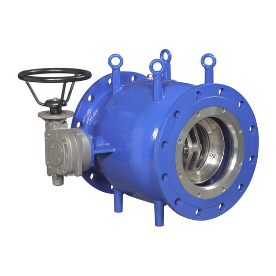
- Page 1 Operating and maintenance instructions ® VAG RIKO Plunger Valve KAT-B 2010 Edition 7-1 / 01-18...
-
Page 2: Table Of Contents
Content General We reserve the right to make technical changes and use similar or higher quality materials. Drawings are non-binding. 1.1 Safety 1.2 Proper use 1.3 Marking Transportation and Storage 2.1 Transportation 2.2 Storage Product and function description 3.1 Features and function description 3.2 Fields of application 3.3 Performance limits 3.4 Proper and improper mode of operation... -
Page 3: Safety
The name plate on the body provides the following These operating and maintenance instructions must information: be observed at all times and used jointly with the VAG Installation and Operating Instructions for Valves. The Name of the manufacturer user must not change or modify this product or the Nominal width of the valve mounting parts / fittings supplied with it. -
Page 4: Fields Of Application
3.2 Fields of application must be plane-parallel and in true alignment. Misaligned pipe- lines must be put into a true alignment position before the valve As the seals of the VAG RIKO ® Plunger Valve are made of EPDM is installed. Otherwise the body may be exposed to impermissibly... -
Page 5: Position Of Installation
When the valve is installed it must be free of • When using polluted mediums a filter with a suitable mesh size dust and dirt. VAG does not assume any liability for consequential has to be provided upstream of the valve to sustain the function damage caused by dirt, grit etc. - Page 6 Indentification mark for the “seat of the valve” Picture 4: Permissible / impermissible positions of installation and flow directions VAG Operating and maintenance instructions • 6...
-
Page 7: Putting Into Operation And Operation
• in close position depending on the limit. Carefully purge all newly installed pipeline systems in order to re- These switches are adjusted at VAG factory. The torque switches move any foreign particles. Should residues or dirt particles be act as overload protection in the intermediate positions. In case... -
Page 8: Maintenance And Servicing
The body seals can be replaced, if required, depending on the type of fluid conveyed. 7.3 Maintenance and replacement of parts The spare parts needed can be found in the spare parts list in chapter “7.3.1 Design”. VAG Operating and maintenance instructions • 8... -
Page 9: Design
7.3.1 Design 1.15 1.14 1.13 1.12 7 9 8 2.10 Pos. Description Material Spare part Body EN-JS 1030 (GGG 40) Profile sealing ring EPDM Retaining ring 1.4301 Quad O-ring EPDM Hexagon socket head cap screw A4-70 Bearing flange EN-JS 1030 (GGG 40) Bearing bush G-CuSn12 Thrust washer... -
Page 10: Replacing The Profile Sealing Ring (Position 1.2)
1.12 Hexagon cap screw, bearing cover 1.13 Threaded pin, bearing cover 2.10 Hexagon socket head cap screw, retaining ring, 1000 1600 2500 piston 8 Nut, gear box 1650 Table 4 VAG Operating and maintenance instructions • 10... -
Page 11: Trouble-Shooting
Trouble-shooting For all maintenance and repair work please observe the general safety instructions under Section 7.1. Problem Possible cause Remedial action Unfavourable installation position and thus unfavourable flow at the valve (e.g. Change installation position (cf. Section 4.3) installed to closely behind the elbow) Valve makes noises Check design and/or operational data;... - Page 12 Dimensions of multiple-orifice or slotted cylinders to large Valve operating beyond the design limits Check design and/or operational data; if Cavitation in valve required, change resistance in valve by using other internals. Operational data have been changed www.vag-group.com info@vag-group.com...
Need help?
Do you have a question about the RIKO and is the answer not in the manual?
Questions and answers