Table of Contents
Advertisement
Quick Links
Advertisement
Table of Contents

Subscribe to Our Youtube Channel
Related Manuals for National Instruments NI CB-2162


Summary of Contents for National Instruments NI CB-2162
- Page 1 Artisan Technology Group is your source for quality new and certified-used/pre-owned equipment SERVICE CENTER REPAIRS WE BUY USED EQUIPMENT • FAST SHIPPING AND DELIVERY Experienced engineers and technicians on staff Sell your excess, underutilized, and idle used equipment at our full-service, in-house repair center We also offer credit for buy-backs and trade-ins •...
-
Page 2: Table Of Contents
Develop and interface to prototype circuits • Probe DIO and control channels This guide explains how to set up and use the NI CB-2162 single-ended DIO accessory. To ensure the specified EMC performance of the device connected to the Caution NI CB-2162, this product must be installed in a shielded enclosure and used only with shielded cables and accessories. -
Page 3: What You Need To Get Started
Resistors and 10-pin single-inline packaged resistor networks for pull-up/pull-down and series termination The NI CB-2162 ships populated with a 0 Ω resistor. A 50 Ω resistor also is included for optional STROBE/PFI 5 series termination. 30-gauge wire ... -
Page 4: Parts Locator Diagram
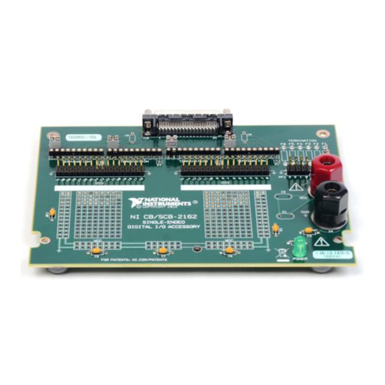
Parts Locator Diagram Refer to Figure 1 to locate connectors and components on the NI CB-2162. Figure 1. NI CB-2162 Parts Locator Diagram F6 F5 F4 F3 F2 F1 4/DDC CLKOUT STROBE 68-Pin Digital Data & Control (DDC) Connector Prototyping Area Power and Ground Solder Pads... -
Page 5: Installing Cables
Attach the other end of the cable assembly to the DDC connector of the NI CB-2162 and secure them together with the captive screws on the cable connector. -
Page 6: Connecting Signals
Before powering down the digital waveform generator/analyzer module, Caution remove power from the prototyping area of the NI CB-2162. NI is not liable for any damage resulting from improper signal connections. Figure 3 shows the DDC connector pinout of the NI CB-2162. -
Page 7: Artisan Technology Group - Quality Instrumentation ... Guaranteed | (888) 88-Source | Www.artisantg.com
Refer to your device documentation for support. The NI CB-2162 provides connectivity to up to 32 of the single-ended DIO channels of an NI digital waveform generator/analyzer. The 32 DIO channels are divided into two bundles of 16 ×... -
Page 8: Artisan Technology Group - Quality Instrumentation ... Guaranteed | (888) 88-Source | Www.artisantg.com
Using 1 × 2 Header Receptacles Each signal and ground header pair is labeled on the NI CB-2162 and in Figure 1. These header pairs are arranged so that you can make quick connections using a 1 × 2 header receptacle to a coaxial cable assembly. -
Page 9: Artisan Technology Group - Quality Instrumentation ... Guaranteed | (888) 88-Source | Www.artisantg.com
Using a Ribbon Cable The header pairs on the NI CB-2162 are available for single wire probing. You also can use 32-pin ribbon cables to easily connect a large number of channels to other devices. Cable type and quality can dramatically affect how well the signal integrity is maintained. NI recommends using short twisted-pair ribbon cables. -
Page 10: Terminating Signals
Termination of high-speed digital signals is necessary to prevent signal reflections and to force signal channels to a known state when no signal is present. Sockets for terminating resistors are connected to all DIO and control channels on the NI CB-2162. These sockets are labeled in Figure 1. -
Page 11: Artisan Technology Group - Quality Instrumentation ... Guaranteed | (888) 88-Source | Www.artisantg.com
To minimize the effect of stubs, termination is placed at the end of the signal path. If your signal transmission line ends on the NI CB-2162, you can use the provided termination socket. If your signal terminates somewhere other than the NI CB-2162, NI recommends terminating the transmission line at the final signal destination. -
Page 12: Artisan Technology Group - Quality Instrumentation ... Guaranteed | (888) 88-Source | Www.artisantg.com
R2 of Figure 9. NI CB-2162 User Guide | © National Instruments | 11 Artisan Technology Group - Quality Instrumentation ... Guaranteed | (888) 88-SOURCE | www.artisantg.com... -
Page 13: Artisan Technology Group - Quality Instrumentation ... Guaranteed | (888) 88-Source | Www.artisantg.com
PFI 3 (W3) J11, J12 (F6) Parallel (pull-down) Depending on the revision of your NI CB-2162, termination sockets may be Notes alternately referred to as the name in parenthesis. Refer to the help file for your device for information about the function of DDC CLK OUT/PFI_4 and STROBE/PFI_5. -
Page 14: Using The Ni Cb-2162 Prototyping Area
Specifications voltage ranges. The green power LED is lit when a positive voltage is applied to the NI CB-2162. However, if negative voltage is applied, the Power LED does not light. The power connectors and LED for the prototyping area are labeled in Figure 1. -
Page 15: Mounting The Ni Cb-2162 In An Enclosure
VHDCI panelette and three screws. The CA-1000 includes the standoffs that are required to attach the NI CB-2162 to the bottom of the CA-1000. If you want to rack-mount the NI CB-2162 after it is installed in the CA-1000, you can purchase rack-mount side panels (777665-01). -
Page 16: Artisan Technology Group - Quality Instrumentation ... Guaranteed | (888) 88-Source | Www.artisantg.com
Remove the top cover. Figure 11. Remove Cover from CA-1000 Enclosure CA-1000 Enclosure Top Cover 4-40 × 1/4 in. Screws NI CB-2162 User Guide | © National Instruments | 15 Artisan Technology Group - Quality Instrumentation ... Guaranteed | (888) 88-SOURCE | www.artisantg.com... - Page 17 Screw the standoffs onto the threaded screws in the locations shown in Figure 12. Position the NI CB-2162 on the standoffs of the CA-1000. Secure the NI CB-2162 in the bottom of the CA 1000 using two of the screws provided in the NI CB-2162 CA-1000 Mounting Kit.
-
Page 18: Specifications
I/O Connector Panelettes Figure 13. Install Blank I/O Panelettes I/O Panelettes Screws The NI CB-2162 is now installed in the CA-1000 enclosure. Specifications Digital I/O DIO channels ............ 32, single-ended Control I/O channels......... 6, single-ended Resistors Number ............. 2 Type .............. -
Page 19: Artisan Technology Group - Quality Instrumentation ... Guaranteed | (888) 88-Source | Www.artisantg.com
At the end of the product life cycle, all products must be sent to EU Customers a WEEE recycling center. For more information about WEEE recycling centers, National Instruments WEEE initiatives, and compliance with WEEE Directive 2002/96/EC on Waste and Electronic Equipment, visit ni.com/environment/... -
Page 20: Where To Go For Support
National Instruments corporate headquarters is located at 11500 North Mopac Expressway, Austin, Texas, 78759-3504. National Instruments also has offices located around the world. For telephone support in the United States, create your service request at or dial ni.com/support... -
Page 21: Artisan Technology Group - Quality Instrumentation ... Guaranteed | (888) 88-Source | Www.artisantg.com
NI product. Refer to the Export Compliance Information at ni.com/legal/export-compliance for the National Instruments global trade compliance policy and how to obtain relevant HTS codes, ECCNs, and other import/export data. NI MAKES NO EXPRESS OR IMPLIED WARRANTIES AS TO THE ACCURACY OF THE INFORMATION CONTAINED HEREIN AND SHALL NOT BE LIABLE FOR ANY ERRORS. -
Page 22: Artisan Technology Group - Quality Instrumentation ... Guaranteed | (888) 88-Source | Www.artisantg.com
Artisan Technology Group is your source for quality new and certified-used/pre-owned equipment SERVICE CENTER REPAIRS WE BUY USED EQUIPMENT • FAST SHIPPING AND DELIVERY Experienced engineers and technicians on staff Sell your excess, underutilized, and idle used equipment at our full-service, in-house repair center We also offer credit for buy-backs and trade-ins •...
Need help?
Do you have a question about the NI CB-2162 and is the answer not in the manual?
Questions and answers