Table of Contents
Advertisement
Advertisement
Table of Contents

Related Manuals for Spacelabs 91518


Summary of Contents for Spacelabs 91518
- Page 1 Multigas Analyzer 91518 Service Manual 070-1328-00 Rev. E...
- Page 2 All rights reserved. Contents of this publication may not be reproduced in any form without the written permission of Spacelabs Medical. Products of Spacelabs Medical are covered by U.S. and foreign patents and/or pending patents. Printed in U.S.A. Specifications and price change privileges are reserved.
-
Page 3: Table Of Contents
Table of Contents Contents Page Introduction Overview................. 1-1 Compatibility . -
Page 5: Overview
Controls and Connectors ..............4 Overview The 91518 is a multigas analyzer used primarily in an operating room environment to measure the CO produced by a patient and the O O, and anesthetic agents being administered. -
Page 6: Compatibility
Introduction Compatibility ® The 91518 Multigas Analyzer is designed for use with Ultraview SL, Ultraview, and UCW monitors. ™ Ultraview SL • Ultraview SL2400 (91369), SL2600 (91370), SL2700 (91387-27), SL2800 (91387-28) ® Ultraview • UCW (90385)*, Ultraview 1700 (90387)*, Ultraview 1500 (90363), Ultraview 1600 (90364), Ultraview 1050... -
Page 7: Environmental Requirements
Introduction Environmental Requirements Table 1 lists the environmental requirements, including temperature, for operating and storing the 91518 Multigas Analyzer. Table 1: Environmental Requirements Operating Storage 18° to 28° C (64.4° to 82.4° F), Temperature -25° to 70° C (-13° to 158° F) ±5°... -
Page 8: Controls And Connectors
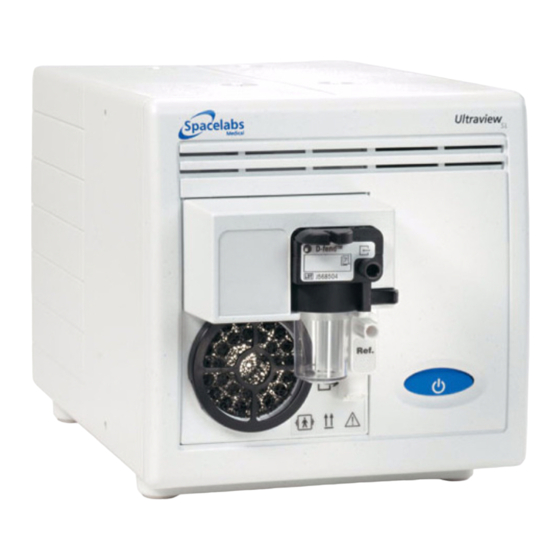
Controls and Connectors The blue power ON/OFF switch is located on the front of the analyzer. All other multigas analyzer functions are controlled using the touch keys on Spacelabs Healthcare monitors. Front View Figure 1-2: Front view of the 91518 Multigas Analyzer... - Page 9 Introduction Rear View Figure 1-3: Rear of 91518 Multigas Analyzer 9 pin SDLC connector (J2) RS-232 connector (J1) SDLC terminator Equipotential ground terminal 26-pin SDLC connector (J3) Power connection 91518 Multigas Analyzer Service Manual...
-
Page 11: Unpacking
Power Up Verification ..............14 Unpacking Before unpacking the 91518 Multigas Analyzer, inspect its shipping container for visible damage. Unpack and remove the multigas analyzer from its container. Check the multigas analyzer's exterior for signs of physical damage. -
Page 12: Multigas Setup
3 Assemble the required cables and terminators for your system configuration (refer to Figure 2-2 for part numbers). 4 Connect the P1 connector of the tee cable (P/N 012-0175-01) to the SDLC jack (J2) on the 91518 rear panel (refer to Figure 1-3 on page 1-5 for rear panel information). - Page 13 ..SDLC P/N 012-0175-01 terminator SDLC P/N 012-0619-00 tee cable jack P/N 012-0507-02 or 012-0242-00 extension cable Figure 2-3: 91518 connections to 90367/69, 91369, 91370 monitors, using extension cable 91518 Multigas Analyzer Service Manual...
- Page 14 3 Assemble the required cables and terminators or your system configuration (refer to Figure 2-4 for part numbers). 4 Connect the P1 connector of the tee cable (P/N 012-0175-01) to the SDLC jack (J2) on the 91518 rear panel (refer to Figure 1-3 on page 1-5 for rear panel information).
- Page 15 ..SDLC terminator P/N 012-0507-02 P/N 012-0152-00 P/N 012-0619-00 tee cable or 012-0242-00 extension cable Figure 2-5: 91518 connections to 90367/69, 91369, 91370 monitors, using Flexport and extension cable 91518 Multigas Analyzer Service Manual...
- Page 16 91387 Monitor Installation To install the 91518 with the 91387 monitor: 1 Verify that the AC power is connected as required by local standards. The 91518 Multigas Analyzer will not require the use of an external power supply. 2 Ensure that the monitor and multigas analyzer are powered OFF.
- Page 17 6 Set the SDLC switch on the 91518 Multigas Analyzer to unterminated ( 7 Connect the Flexport cable (012-0152-00) to J2 of the multigas analyzer. Note: If using more than one Flexport, Spacelabs Healthcare recommends the use of the Flexport Holder (P/N 650-0201-00). To peripheral...
- Page 18 To install the 91518 with 90364, 90491, 90499, and 90387 module housings or monitors: 1 Verify that the AC power is connected as required by local standards. The 91518 Multigas Analyzer will not require the use of an external power supply.
- Page 19 To install the 91518 with 90364, 90491, 90499, and 90387 module housings or monitors: 1 Verify that the and AC power is connected as required by local standards. The 91518 Multigas Analyzer will not require the use of an external power supply.
- Page 20 3 Assemble the required cables for your system configuration (refer to Figure 2-10 for part numbers). 4 Connect the P1 connector of the tee cable (P/N 012-0175-01) to the SDLC jack (J2) on the 91518 rear panel (refer to Figure 1-3 on page 1-5 for rear panel information).
- Page 21 3 Assemble the required cables for your system configuration (refer to Figure 2-11 for part numbers). 4 Connect the P1 connector of the tee cable (P/N 012-0175-01) to the SDLC jack (J2) on the 91518 rear panel (refer to Figure 1-3 on page 1-5 for rear panel information).
- Page 22 AGSS. Refer to the documentation that came with your anesthesia machine to determine if the scavenging line can be connected to the AGSS. 91518 Multigas Analyzer Service Manual 2-12...
- Page 23 The sample gas can also be returned to the patient breathing circuit. You may need an adapter to connect to the patient breathing tubes. Anesthesia machine Multigas Analyzer Figure 2-13: Returning the sample gas to the patient circuit 91518 Multigas Analyzer Service Manual 2-13...
-
Page 24: Power Up Verification
9 Power OFF the analyzer. System Test 1 Verify that the unit has passed the standalone test. 2 Connect the 91518 to a patient monitor as detailed in Multigas Setup on page 2-2. 3 Power ON the patient monitor. 4 Power ON the 91518. - Page 25 14 Hold a finger over the water trap input (or pinch shut the sample line) to block air flow. Verify that the message OCCLUSION - Check System appears on the monitor screen within 30 seconds. 91518 Multigas Analyzer Service Manual 2-15...
- Page 27 Oxygen Measuring Unit ..............9 Overview The 91518 Multigas Analyzer is a side stream gas analyzer, measuring real time concentrations of O , CO O and anesthetic agents (halothane, enflurane, isoflurane, desflurane and sevoflurane).
- Page 28 Theory Figure 3-2: 91518 Detailed block diagram 91518 Multigas Analyzer Service Manual...
-
Page 29: Interface Pcba
The interface PCBA (P/N 670-1319-xx) provides power to and controls the gas analyzer unit. The interface PCBA is responsible for the two-way SDLC communication link with the Spacelabs Healthcare monitor. The interface PCBA transmits processed data from the gas module to the monitor for display and recording. -
Page 30: Gas Analyzer Unit
The 91518 Multigas Analyzer communicates with the Spacelabs Healthcare monitor using a SDLC interface that is common between all current Spacelabs Healthcare monitors and modules. The Multigas Analyzer can use both 9-pin and 26-pin SDLC cables, depending on the Spacelabs monitor that is used. Refer to Multigas Setup on page 2-2. - Page 31 The occlusion valve connection to room air includes a dust filter, and the zero valve connection to room air includes an absorber. Connection Block The connection block contains a sample gas outlet connector and OM unit reference gas inlet (Ref). The inlet is equipped with a dust filter. 91518 Multigas Analyzer Service Manual...
- Page 32 The damping chamber is used to even out the pulsating flow and to silence the exhaust flow. Note: The flow is never reversed toward the patient. To Ref gas port Figure 3-3: Gas sampling system 91518 Multigas Analyzer Service Manual...
- Page 33 The infrared radiation detectors are thermopiles. Figure 3-5: Gas analyzer in principle Concentrations of CO and N O are calculated from absorption measured at 3 to 5 µm (refer to Figure 3-6 on page 3-8). 91518 Multigas Analyzer Service Manual...
- Page 34 From the measuring chamber, the infrared radiation passes into seven tubular light guides with a reflective inner surface. A thermopile detector with an optical filter is located at the other end of each light guide. 91518 Multigas Analyzer Service Manual...
- Page 35 The CPU board also contains the preamplifiers for the TPX sensor and the drivers for valves, fan, pump, and lamp. The multigas analyzer is connected to the analyzer bus through a RS-485 serial channel. 91518 Multigas Analyzer Service Manual...
- Page 36 Theory Figure 3-9: Signal processing Figure 3-10: Control logic 91518 Multigas Analyzer Service Manual 3-10...
- Page 37 The oxygen measuring board contains the specific electronics for the oxygen sensor. The sample flow measurement system and sampling system pressure sensors are on this board. It also contains EEPROMs that store the calibration data for both the gas measuring and OM sensors. 91518 Multigas Analyzer Service Manual 3-11...
- Page 39 • All static-sensitive electronic components are packaged in static-shielding bags. Retain the bag for repackaging the component, should you need to store it or return it to Spacelabs Healthcare for any reason. 91518 Multigas Analyzer Service Manual...
-
Page 40: Preventive Maintenance
If the multigas analyzer has been damaged in any way, check it for proper operation, and verify the accuracy of its measurements. A field service engineer should inspect the 91518 for acceptable performance at 12-month intervals, or at an interval determined to be appropriate by an effective risk-based equipment management program established by the hospital. - Page 41 ETCO values. For the rest of the parameters question marks will display. This completes the functional performance check. If the check passes, proceed with the preventive maintenance. If the check fails, corrective maintenance is necessary. 91518 Multigas Analyzer Service Manual...
- Page 42 To replace the fan air filter: 1 Remove the filter cover from the front of the 91518 (refer to Figure 4-2 on page 4-4) using a small, flat screwdriver. 2 Replace the filter with a new one, or clean the existing one by washing it with water and mild soap.
- Page 43 O-ring over the top of the post. 3 Visually inspect the installation to make sure the O-ring is in the groove, and is not distorted (refer to Figure 4-4). 91518 Multigas Analyzer Service Manual...
- Page 44 The filter element is sealed inside the block. Replacing the filter requires replacement of the entire block. There is no replaceable filter in the block. 2 Install the new O-ring in the recess of the block, and carefully align the replacement block with the front panel. 91518 Multigas Analyzer Service Manual...
- Page 45 • All static-sensitive electronic components are packaged in static-shielding bags. Retain the bag for repackaging the component, should you need to store it or return it to Spacelabs Healthcare for any reason. To disassemble the gas unit: 1 Remove any cables from the back of the enclosure.
- Page 46 (Figure 4-8). Unplug the connector and route the cable to the left, away from the unit’s cavity in the chassis. Figure 4-8: Connector cable 5 Remove the gas unit from the chassis by pulling straight back on the handle until the gas unit clears the enclosure. 6 Remove the handle from the gas bench. 91518 Multigas Analyzer Service Manual...
- Page 47 8 Grasp the front of the gas unit, and with the other hand, pull the metal case straight back and off. Set aside the case, handle, and screws. Figure 4-10: Separating the gas unit from the case Assembly is the reverse of disassembly. A functional check should be performed after the completion of the preventive maintenance procedure. 91518 Multigas Analyzer Service Manual...
- Page 48 2 Remove the small Phillips head screw holding the filter restraint (refer to Figure 4-12). Use a needle nosed pliers or tweezers to lift the filter restraint away from the block. 91518 Multigas Analyzer Service Manual 4-10...
- Page 49 6 Place the new filter element in the pneumatic block. Insert the filter element restraint in the recessed area, and replace the screw. Do not overtighten the screw. 91518 Multigas Analyzer Service Manual 4-11...
- Page 50 (refer to Figure 4-14 on page 4-13). Gently pull the other end barb out of the short tube attached to the pneumatic block G port. 91518 Multigas Analyzer Service Manual 4-12...
- Page 51 3 Remove the two bracket screws ( ; Figure 4-15 on page 4-14) near the ends of the absorber. Lift the bracket slightly and pull out the free end of the absorber. 91518 Multigas Analyzer Service Manual 4-13...
- Page 52 To clean the exterior of monitoring equipment and cables: • Prepare the cleaning solution according to the manufacturer’s instructions. • Wet a clean cloth with the selected cleaning solution. • Remove excess liquid from the cloth and squeeze dry. 91518 Multigas Analyzer Service Manual 4-14...
-
Page 53: Software Updates
Caution: Do not allow liquid to enter the interior of the 91518 Multigas Analyzer. If this should occur, check the unit for proper operation and verify its performance accuracy prior to reuse. Disposable and reusable patient accessories are available for the 91518 Multigas Analyzer. Disposable accessories are for single-patient use only and must not be sterilized or cleaned for reuse on other patients. -
Page 54: Corrective Maintenance
Initially, the 91518 examines the contents of the measurement chamber for the specific signature of each gas and compensates for any difference between the measured value and the expected value. These correction factors are stored in non volatile memory for subsequent use. - Page 55 The excess calibration gas flow is directed through the side port of the tee. It is critical that the excess gas flow be maintained through the flow meter at 20-50 ml/min to ensure that the gas flowing into the 91518 is not being diluted by room air and preventing accurate calibration.
- Page 56 (the pump rate should already be at the default value of 175 ml/min). Note: The 91518 must be powered on for 30 minutes to allow the internal temperatures to stabilize. 91518 Multigas Analyzer Service Manual 4-18...
- Page 57 5.5% 5.3 – 5.7% * Although the gas bottle contains 46.5% O , the 91518 reads O in whole number percentages. 9 If the displayed values of FiO do not fall within the range listed above after the completion of the gas calibration, return to step 3.
- Page 58 CAL GAS IN PROGRESS message. The Spacelabs Healthcare calibration gas supply must be present throughout the entire procedure. After the gas calibration is complete, compensation values will be stored in the nonvolatile memory (NVRAM). Pressing the NO key will return to the Service Cal Mode menu.
- Page 59 The monitor has switched to display the diagnostic (calibration) data values. • The patient has been disconnected from the 91518 in order to supply calibration gases. • The breath detection is disabled, and the displayed values are not based upon breath detection.
- Page 60 IF Boot Code, IF App Code, IF Table Code, FE Code — Respective interface (IF) version numbers Module Options — Refers to the options enabled for the multigas analyzer Monitor Type — Refers to the type of Spacelabs Healthcare monitor being used with the analyzer IF, FE — Interface PCBA and front-end PCBA version numbers General Error Status —...
- Page 61 Leak Check Test The leak test is used to determine if the 91518 leaks by measuring the leak rate after applying pressure. The 91518 should not be in service during a leak test, and power should be disconnected from the unit.
-
Page 62: Disassembly And Fru Replacement
14 Push the rear panel against the mating surfaces in the chassis. Secure the rear panel with four 6-32 × 1/4-inch screws. Tighten the captive screw. Do not overtighten the screws. Replacement of the PCBA interface is complete. 91518 Multigas Analyzer Service Manual 4-24... - Page 63 Pull the side cover away from the chassis. Repeat this step to remove the other side cover from the chassis. 91518 Multigas Analyzer Service Manual 4-25...
- Page 64 Set the chassis aside and save the screws. Figure 4-22: PCBA removal 10 Remove the four screws from the bezel assembly, then remove the bracket screws holding the ON/OFF switch cable assembly. Save the bracket and screws. Figure 4-23: PCBA removal 91518 Multigas Analyzer Service Manual 4-26...
- Page 65 25 Push the rear panel against the mating surfaces in the chassis. Secure the rear panel with four 6-32 × 1/4-inch screws, then torque the screws to 8 lb/in. Tighten the captive screw. Do not overtighten the screws. Replacement of power switch assembly is complete. 91518 Multigas Analyzer Service Manual 4-27...
-
Page 67: Tools And Equipment
Before PCBA-level troubleshooting is initiated, first establish that there is a fault with the analyzer. The 91518 Multigas Analyzer comes with some diagnostic capabilities. When certain error conditions are detected, messages are displayed in the waveform zone on the monitor. Message text flashes to indicate that there is a problem. -
Page 68: Troubleshooting
-or- as necessary. ■ If the condition persists for a Leak Detected - period greater than Check system 40 seconds then the pump will be turned off and the second message will be displayed. 91518 Multigas Analyzer Service Manual... - Page 69 Wait until CAL GAS calibration is PROGRESS progress. completed and the message goes away. ■ ■ ZERO IN PROGRESS A Zero calibration is in Wait until Zero calibration is progress. completed and the message goes away. 91518 Multigas Analyzer Service Manual...
- Page 70 Anesthetic Agent gases. CHECK OR REPLACE ■ There is no water trap ■ Install a water trap. WATER TRAP installed in the holder. ■ Replace the water trap. ■ The water trap is full. 91518 Multigas Analyzer Service Manual...
- Page 71 Check connections and check OBSERVED performed while there was a for a broken water trap. Perform leak in the sample circuit. leak test. Verify the anesthesia delivery devices and vaporizer calibrations. ■ Assure vaporizer accuracy. 91518 Multigas Analyzer Service Manual...
- Page 72 If the message persists, contact your biomed or a qualified field service engineer. 91518 Multigas Analyzer Service Manual...
-
Page 73: Field Replaceable Parts
Box, White, Corrugated, 8 × 5 × 3 004-0772-00 Foam, Pink Anti-static, 8 × 5 × 1 OVER 1/2 004-0774-00 Convoluted Bag, Polyethelene, 2 mil, 6" × 9" 004-0336-00 Label, 1/2" × 1 3/4" 334-1554-00 91518 Multigas Analyzer Service Manual... - Page 74 Power Supply, 90W, 18V, Medical Grade 119-0480-00 PCBA, Multigas interface 670-1319-01-X Pump, Air, 5-15 VDC 57313-HEL Nafion Tubing, 300 mm 717-0051-00 Silicone Tube, Transparent, 1.6 mm ID, 717-0055-00 25 mm length Fan, Compact Airway Module 886213 91518 Multigas Analyzer Service Manual...
- Page 75 Sample Line, Agent, w/sampling Tee, 7', 015-0312-01 50/BX Sample Line, Agent, Male Luer, SPU, 10', 162-0046-01 50/bx 7-foot sample line 162-0047-01 Gas pressure regulator 369009-002 SDLC cable 012-0175-xx SDLC terminator 012-0507-xx Flow meter, Brooks model 1355 Exhaust scavenging line 717-0408-00 91518 Multigas Analyzer Service Manual...
- Page 76 Parts Table 4: Miscellaneous Parts Description Part Number Multigas, D-O Module A, 91518 010-1651-00-X HANDLE, MODULE, MULT GAS, 91518 367-0835-00 PANEL, REAR, DO MODULE, 91518 333-0901-00 PANEL, REAR, PCBA MULTIGAS, 91518 333-0902-00 ENCLOSURE, LEFT HALF, 91518 437-5050-00 ENCLOSURE, RIGHT HALF, 91518...
-
Page 77: Drawings
Parts Drawings Description Drawing Sheets 91518 Assembly 91518 Schematics P/N 676-0719-00 91518 Multigas Analyzer Service Manual... -
Page 79: Electromagnetic Emissions
IEC 61000-3-2 operating with the 91518 Multigas Analyzer. OEM power supply does not cause any Voltage measureable voltage changes and less than 0.1% fluctuations/flicker Complies short-term flicker while operating with the 91518 IEC 61000-3-3 Multigas Analyzer. 91518 Multigas Analyzer Service Manual... - Page 80 Note: U is the AC mains voltage prior to application of the test level. All power line immunity tests were performed on the host monitor/module housing at 120 VAC/60 Hz and 230 VAC/50 Hz. 91518 Multigas Analyzer Service Manual...
-
Page 81: Frequency Separation Distances
** Over the frequency range 150 kHz to 80 MHz, field strengths should be less than [ V ] V/m. 91518 Multigas Analyzer Service Manual... - Page 82 Note 1: At 80 MHz and 800 MHz, the separation distance for the higher frequency range applies. Note 2: These guidelines may not apply in all situations. Electromagnetic propagation is affected by absorption and reflection from structures, objects, and people. 91518 Multigas Analyzer Service Manual...
- Page 83 Appendix B — Symbols The following list of international and safety symbols describes all symbols used on Spacelabs Healthcare products. No one product contains every symbol. HELP Key Keyboard Connection SPECIAL FUNCTIONS Key Mouse Connection RECORD Key START/STOP Key NORMAL SCREEN Key...
- Page 84 Return to Prior Menu Clock/Time Setting Key TREND/TIMER Key HELP (Explain Prior Screen) Key Keypad Activate Recorder for Graphics Indoor Use Only START (NIBP) Key Auto Mode (NIBP) Television; Video Display Video Output Output (Non-terminated) No Output (Terminated) 91518 Multigas Analyzer Service Manual...
- Page 85 Defibrillator Synchronization Gas Exhaust Foot Switch Enlarge, Zoom Delete PCMCIA Card Event Keep Dry Fragile; Handle with Care 12,200 m Environmental Shipping/Storage This Way Up Altitude Limitations Environmental Shipping/Storage Environmental Shipping/Storage Temperature Limitations Humidity Limitations 91518 Multigas Analyzer Service Manual...
- Page 86 Gas Sampling Port Gas Return Port Low Priority Alarm Nurse Call High Priority Alarm Medium Priority Alarm Alarms Paused Nurse Alert Interface Battery Status Alarm OFF Battery Replace only with the appropriate Low Battery battery. 91518 Multigas Analyzer Service Manual...
- Page 87 IEC 60601-1 Type B equipment. IEC 60601-1 Class II equipment, The unit displaying this symbol double-isolated. The unit displaying contains an adequate degree of this symbol does not require a protection against electric shock. grounded outlet. 91518 Multigas Analyzer Service Manual...
- Page 88 Caution About Potential Danger to a Warning Caution Human Beings Device Noninvasive Blood Pressure (NIBP), Fetal Monitor Connection (Analog) Neonate Fetal Monitor Connection Physiological Monitor Connection RS-232 (Digital) RS-232 (Digital) Symbol Set, Adult/Pediatric Cuff Sizes Symbol Set, Neonatal Cuff Sizes 91518 Multigas Analyzer Service Manual...
- Page 89 NIBP Cuff, Adult Size NIBP Cuff, Child Size ADULT CHILD (23 to 33 cm) (12 to 19 cm) NIBP Cuff, Infant Size NIBP Cuff, Neonatal 1 Size INFANT NEONATAL 1 (8 to 13 cm) (3 to 6 cm) 91518 Multigas Analyzer Service Manual...
- Page 90 List of Rooms Arrows Printer Recycle Service Message Non Sterile PVC-Free (Polyvinyl Chloride) LATEX Latex-Free Do Not Reuse; Single Use Only Radio transmitting device; elevated Reusable levels of non-ionizing radiation Reference Number or Batch Code Order Number 91518 Multigas Analyzer Service Manual...
- Page 91 Arterial/Venous Oxygen Difference Arterial Oxygen EEG, EMG, or ECG Channel EEG Channels - CH1, CH2, CH3, Centimeters of Water EMG Channel - CH5 C.O. Cardiac Output Venous Oxygen Diastolic Electrocardiogram Electroencephalogram Electromyogram Electrosurgical Interference ESIS External Suppression 91518 Multigas Analyzer Service Manual...
- Page 92 Measured by Pulse Oximetry SVO2 SvO2 Mixed Venous Oxygen Saturation Systolic Temperature 1 Temperature 2 TEMP Temperature Temperature 3 temp Temperature 4 Uterine Activity or Umbilical Artery Oxygen Consumption Vacuum Connection Umbilical Venous 91518 Multigas Analyzer Service Manual B-10...
Need help?
Do you have a question about the 91518 and is the answer not in the manual?
Questions and answers