
Related Manuals for Spacelabs qube 91390


Summary of Contents for Spacelabs qube 91390
- Page 1 91390 070-2451-01 Rev. F | October 2014 www.spacelabshealthcare.com...
- Page 2 Spacelabs Healthcare as field repairable. Spacelabs Healthcare is committed to providing comprehensive customer support beginning with your initial inquiry through purchase, training, and service for the life of your Spacelabs Healthcare equipment. CORPORATE OFFICES Corporate Headquarters Spacelabs Healthcare, Inc.
-
Page 3: Table Of Contents
Table of Contents Introduction Overview..........................1-1 Warnings, Cautions, and Notes.................. 1-2 Product Specifications ....................1-3 Electrical Specifications....................1-5 Classification ......................1-5 Environmental Requirements ..................1-6 Transport and Storage ................... 1-6 Operating ........................1-6 Expected Service Life....................1-6 Monitor Options....................... 1-7 Product Overview ...................... - Page 4 9 1 3 9 0 Q U B E Theory CPU PCB ..........................3-1 Battery Charger and Power Supply Subsection (on CPU PCB) ....3-4 Li-Ion Batteries........................ 3-5 Battery Switch PCBA for Options B and C ............3-7 Monitor Docking PCBA and Connector PCBA............ 3-8 Front Bezel Assembly ....................
- Page 5 9 1 3 9 0 Q U B E Insert Recorder Paper ..................4-29 To insert a roll of paper..................4-29 Dock Connector Covers for Option A ............4-29 Removal of Pod Interface PCBA for Options A and B ......4-30 Reinstallation of the Pod Interface PCBA ...........
- Page 6 9 1 3 9 0 Q U B E Keyboard, Mouse, or Barcode Scanner ............5-29 Parts Overview..........................6-1 Parts List ..........................6-2 Option A ........................6-2 Option B ........................6-4 Option C ........................6-7 Assembly Drawings and Schematics..............6-10 Glossary A Appendix A —...
-
Page 7: Introduction
Q U B E Introduction Overview Spacelabs Healthcare designs and manufacturers its products under good manufacturing practices and in compliance with all applicable regulatory requirements. To make sure that the product operates correctly in accordance with these guidelines, trained technicians using Spacelabs Healthcare authorized replacement parts maintain this product. -
Page 8: Warnings, Cautions, And Notes
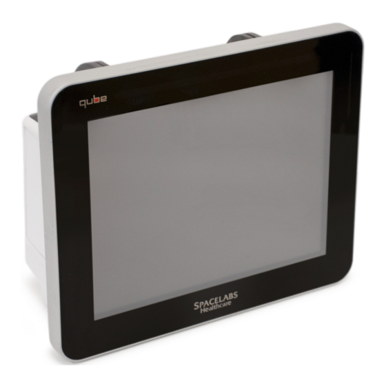
9 1 3 9 0 N T R O D U C T I O N Q U B E Figure 1-1 91390 qube monitor configuration options qube with both printer and battery slots (option A) qube with only printer slot (option B) qube with no printer or battery slots (option C) Note: For more details refer to Table 1-1 on page 4. -
Page 9: Product Specifications
9 1 3 9 0 Q U B E N T R O D U C T I O N Product Specifications Refer to Basic Components on page 1-9 for more information. Product Specifications Physical Dimensions Height 26.2 cm 10.3 inches Width 31.5 cm 12.4 inches... - Page 10 9 1 3 9 0 N T R O D U C T I O N Q U B E Table 1-1 Qube Configuration Options Connectors Internal Recorder Slot 1 on right panel 1 on right panel not included Front Integrated Alarm Light 1 on top, front, and back of 1 on front of display not included...
-
Page 11: Electrical Specifications
9 1 3 9 0 Q U B E N T R O D U C T I O N Electrical Specifications Classification Warning: • Use designated power supply only. • Do not modify this equipment without the authorization of the manufacturer. -
Page 12: Environmental Requirements
Replace the listed items especially if you use them beyond the service life range. Perform safety checks and maintenance of the monitor on regular schedules. Spacelabs Healthcare offers a refurbishment program for equipment that has passed its expected service life. Contact your local service representative for more information. -
Page 13: Monitor Options
Patient Data Logger (PDL); presents an ASCII data stream of patient name and vital sign data to the serial port in a pre- defined format Dynamic Network Access (DNA); Spacelabs Healthcare proprietary version of the Citrix ICA Client connects and interacts with remote applications hosted on Citrix servers. -
Page 14: External Ac Power Supply
9 1 3 9 0 N T R O D U C T I O N Q U B E External AC Power Supply The external AC supply that powers the monitor meets worldwide safety and EMC requirements. The external AC supply provides 20 VDC. -
Page 15: Basic Components
9 1 3 9 0 Q U B E N T R O D U C T I O N • Resolution 1024 x 768 • Active Lines 768 • Active Pixels 1024 Table 1-3 Display Specifications Parameter Minimum Typical Maximum Unit Remarks... -
Page 16: Battery Indicators
9 1 3 9 0 N T R O D U C T I O N Q U B E Callout Description Symbol Number Integrated Battery Slot closed* Refer to To change batteries without interruptions while operating on battery power page 1-15 for details. - Page 17 9 1 3 9 0 Q U B E N T R O D U C T I O N Figure 1-4 Battery charger and AC/DC power indicators Table 1-4 Power Indicators (only shown when AC is connected) Description Symbol on panel AC/DC Power Indicator - External power supply is connected to the monitor and the AC mains.
- Page 18 9 1 3 9 0 N T R O D U C T I O N Q U B E Figure 1-5 Back Panel of Qube* Description Symbol on panel Integrated Alarm Light* POD Connection such as Capnography Pod.* Remote Alarm Output - Nurse Alert* Refer to Alarm Relay for option A on page 2-15 for...
-
Page 19: Energy Saving Mode (Battery)
9 1 3 9 0 Q U B E N T R O D U C T I O N Description Symbol on panel 75 mm VESA Mounting Pattern Handle * Not all of the qube configuration options include these items. For more details, refer to Qube Configuration Options page 1-4. -
Page 20: Batteries And Recharging Batteries
Signal strength and radio system congestion can contribute to waveform gaps over the wireless network. Should this be a persistent issue, consult with a Spacelabs Healthcare field service representative. Batteries and Recharging Batteries For option A, the monitor uses smart batteries, and at least one battery must be installed for normal operations. -
Page 21: To Change Batteries Without Interruptions While Operating On Battery Power
The qube monitor and smart rechargeable Li-Ion batteries and cells do not overheat, they have internal protection devices. Overexposure to heat will activate one of these devices and may permanently disable the battery. If this happens, contact Spacelabs Healthcare to purchase a replacement battery. To change batteries without interruptions while... -
Page 22: Architecture
9 1 3 9 0 N T R O D U C T I O N Q U B E Table 1-5 Battery power level messages and tones dark gray outline around a solid black battery icon shows that a battery slot is empty. After you install a battery into the slot, the battery icon shows a white outline and the current charge level of the battery.. -
Page 23: Directory Of Keys
9 1 3 9 0 Q U B E N T R O D U C T I O N • USB support (USB2) • Optional mini-PCI Wireless interface for 802.11a/b/g devices • External Video (Digital DVI) • 5-wire resistive touchscreen •... - Page 24 9 1 3 9 0 N T R O D U C T I O N Q U B E 1 - 1 8 www.spacelabshealthcare.com...
-
Page 25: Setup
This inventory must include serial numbers, model numbers, and all options and cables received. Carefully examine these items for shipping damage. If you find any damage, immediately notify the freight company and Spacelabs Healthcare. www.spacelabshealthcare.com 2 - 1... -
Page 26: Display Assembly
• All static-sensitive electronic components are packaged in static-shielding bags. Keep the bag in case you must repackage the component to store it or return it to Spacelabs Healthcare for any reason. • For options B and C, the battery switch must be set to ON prior to use. -
Page 27: Input/Output Connections (Internal And External)
9 1 3 9 0 Q U B E E T U P Input/Output Connections (Internal and External) This section defines the I/O connections. The back panel includes: • DC Input Power connector • SDLC (Flexport) connector • Pod interface connector (SDLC protocol): options A and B •... - Page 28 IBM Synchronous Data Link Control specification, and uses its Non-Switched Multipoint Half-Duplex configuration. This interface is compatible with all of Spacelabs Healthcare Flexports. The CPU board always provides the SDLC clock. The SDLC clock frequency is 3.7847 MHz ±100 ppm. The pinout for this connector is...
- Page 29 9 1 3 9 0 Q U B E E T U P Remote Nurse Alert Connector - The Remote Nurse Alert connector is primarily designed to provide 14 Pin for option A a contact closure to the outside world to indicate an alarm condition.
- Page 30 9 1 3 9 0 E T U P Q U B E DVI Digital Video Output This DVI-D video connector (P207) is an output to an optional Connector - 29 PIN DVI-D secondary display. The voltage levels on these connectors are compatible with the EIA-RS343A standard.
- Page 31 9 1 3 9 0 Q U B E E T U P DC Power Input Connector There is one DC Power input connector (P204). on the back of the unit. The DC Power Input connector mates to an external AC/DC converter supply.
- Page 32 9 1 3 9 0 E T U P Q U B E USB Connectors (4 for option A, There are two dual USB type-A connectors which allow connection 2 for options B and C) of up to 4 USB devices. The type of USB devices supported are limited to keyboards, mice, barcode readers, and USB flash drives.
-
Page 33: Power Led
9 1 3 9 0 Q U B E E T U P Power LED The monitor has a recessed momentary push-button switch on the right side to toggle the unit between ON and OFF. To turn OFF the monitor, hold the On/Off switch for three seconds. When you power off the monitor, it also turns the power off to all devices drawing power from the monitor, such as keyboards, mice, barcode readers, Flexports, Pod interfaces, and printers. - Page 34 9 1 3 9 0 E T U P Q U B E Warning: Unreliable system operation will occur if the SDLC bus is not correctly terminated or the maximum cable length is exceeded. Flexport interfaces must be attached to the most distal module housing on the SDLC bus. Figure 2-2 Qube Option A Connected to the 90499 Module Housing Figure 2-3 Qube Option B Connected to the 90499 Module Housing 2 - 1 0...
- Page 35 9 1 3 9 0 Q U B E E T U P Figure 2-4 Qube Option C Connected to the 90499 Module Housing If no supplementary module housings are present (not including the module slot on the monitor), then directly connect external devices to the SDLC connector on the monitor (refer to Figure 2-5,...
- Page 36 9 1 3 9 0 E T U P Q U B E Figure 2-6 Qube Option B Connected Directly to Flexports Figure 2-7 Qube Option C Connected Directly to Flexports If one or more supplementary module housings are present, Flexport devices are connected to connector J2 on the 90499 supplementary module housings.
- Page 37 9 1 3 9 0 Q U B E E T U P If multiple module housings are present, external devices must be connected to the last module housing in the daisy-chain (the housing electrically farthest from the monitor on the SDLC bus). Even though multiple connectors can be available, only the SDLC connector on the most distal module housing can be used for connecting external devices.
- Page 38 9 1 3 9 0 E T U P Q U B E Figure 2-9 Qube Option B Connected to 90499 Module Housing and Flexports Figure 2-10 Qube Option C Connected to 90499 Module Housing and Flexports 2 - 1 4 www.spacelabshealthcare.com...
-
Page 39: Sdlc Cable Interconnection
E T U P SDLC Cable Interconnection To ensure Electromagnetic interference (EMI) compliance, the appropriate Spacelabs Healthcare 9-pin connector must be used. Refer to the Module Housing Service Manual (P/N 070-0680-xx). SDLC Bus Termination The SDLC bus must be properly terminated for correct operation. If... - Page 40 9 1 3 9 0 E T U P Q U B E Warning: Data interface connectors on this device are Ground (Earth) referenced! • Only connect this device to other medical equipment suitable for use in the Patient Vicinity. •...
-
Page 41: Power-On Test
9 1 3 9 0 Q U B E E T U P +5 V common Relay maximum ratings: 28 V AC/DC 0.25 A relay ALMON +12 V μ Figure 2-14 Alarm 2 (Low Priority) Relay Schematic Power-ON Test Each time the monitor is powered ON: •... - Page 42 9 1 3 9 0 E T U P Q U B E 2 - 1 8 www.spacelabshealthcare.com...
-
Page 43: Theory
9 1 3 9 0 Q U B E Theory CPU PCB The CPU PCB combines the CPU core, power supplies, Li-Ion battery charger, touchscreen interface, USB subsystem, ATI ES1000 graphics processor and all other I/O interfaces (refer to Figure 3-1 on page 3-1). - Page 44 9 1 3 9 0 H E O R Y Q U B E A PCI bus is used to communicate to the ATI / ES1000 GPU, USB host controller, and optional wireless card (refer to Figure 3-2 page 3-2). P/O CPU PCBA 670-1573-xx...
- Page 45 9 1 3 9 0 Q U B E H E O R Y P/O CPU PCBA 670-1573-xx P/O CPU FPGA PGM MISC I/O RC RX/TX SMC1 SMC2 TO/FROM I2C BUS SPI BUS MON-DOCK PCBA 11.4MHz Clock RC RX/TX RKEY FPGA PGM FROM J50 FPGA...
-
Page 46: Battery Charger And Power Supply Subsection (On Cpu Pcb)
9 1 3 9 0 H E O R Y Q U B E Battery Charger and Power Supply Subsection (on CPU PCB) DC_IN TO/FROM MON-DOCK PCBA P/O CPU PCBA 670-1573-xx BATTERY CONNECTOR PCBA BATT B 670-1555-xx BATT A DC_IN 3.3VAO FP LEDs &... -
Page 47: Li-Ion Batteries
9 1 3 9 0 Q U B E H E O R Y The LTC1960 battery charger IC interfaces with the AO MCU. It is responsible for load switching between AC and battery or batteries, and direct communication via SMBUS protocol to the Li-Ion smart batteries. - Page 48 9 1 3 9 0 H E O R Y Q U B E The primary protection circuit also provides over-temperature protection and prevents the battery from discharging at temperatures =>75º C. Then, once the battery temperature has cooled to <=65º C, it allows discharging again. If the battery reaches 85º...
-
Page 49: Battery Switch Pcba For Options B And C
9 1 3 9 0 Q U B E H E O R Y Battery Switch PCBA for Options B and C P/O CPU PCBA DC_IN 670-1573-xx DC_IN TO/FROM MON-DOCK PCBA BATTERY CONNECTOR PCBA 670-1658-xx DC_IN BATTERY TO MUX 2 SENSE V BATT 2 V BATT 1 BATTERY... - Page 50 9 1 3 9 0 H E O R Y Q U B E Figure 3-6 Battery Switch on Bottom Left of the Monitor This switch is designed to remove the batteries from the circuit during shipment and recessed to prevent inadvertent contact from changing its position.
-
Page 51: Monitor Docking Pcba And Connector Pcba
9 1 3 9 0 Q U B E H E O R Y Figure 3-8 Battery Switch On Symbol Monitor Docking PCBA and Connector PCBA CONNECTOR PCBA DSB Support removed from 670-1522-xx 670-1522-02 and above PCBAs INTERFACE PCBA P200 670-1559-xx P204 EXTERNAL... -
Page 52: Front Bezel Assembly
9 1 3 9 0 H E O R Y Q U B E Input power from the external power supply is routed through this board for both the monitor and docking station inputs. It also runs through a soft start circuit to limit in-rush current. A 7-port USB Hub is found on the docking station board to expand out USB / DSB. -
Page 53: Pod Interface Pcb
9 1 3 9 0 Q U B E H E O R Y • 5-wire resistive touch panel • LCD display • Backlit ON/OFF button • Integrated alarm light • Battery status / AC connected LED’sand the IR remote keypad receiver. - Page 54 9 1 3 9 0 H E O R Y Q U B E 3 - 1 2 www.spacelabshealthcare.com...
-
Page 55: Maintenance
• All static-sensitive electronic components are packaged in static-shielding bags. Keep the bag in case you must repackage the component to store it or return it to Spacelabs Healthcare for any reason. • Perform cleaning, preventive maintenance, and safety checks annually and following any product disassembly or assembly. -
Page 56: Required Test Equipment
9 1 3 9 0 A I N T E N A N C E Q U B E Required Test Equipment • Electrical Safety Analyzer — Dynatech Nevada 232C or equivalent • Patient Simulator — Dynatech Nevada 300B or equivalent Notes: •... -
Page 57: Equipment Required
UUT — Unit Under Test. Spacelabs Healthcare does not endorse standards to the exclusion of others. Therefore: BE SURE TO CHECK YOUR LOCAL REQUIREMENTS TO MAKE SURE YOUR EQUIPMENT SAFETY TESTS COMPLY WITH LOCAL STANDARDS. -
Page 58: Chassis Leakage Current Tests
For patient lead leakage test instructions, refer to the service manual of the specific module or modules you use. Preventive Maintenance A Spacelabs Healthcare Field Service Engineer or qualified hospital biomedical technician checks the monitor and optional equipment for acceptable performance and electrical safety. Checks are done to make sure that the monitor and option equipment operate according to current requirements. -
Page 59: Functional Tests
9 1 3 9 0 Q U B E A I N T E N A N C E Wait for the Reset Monitor dialog box to display. Click (touch) the Reset Monitor key. The monitor resets. After 15 to 20 seconds, a lighted box will appear in the upper left corner of the screen. -
Page 60: Optional Recorder Assembly For Options A And B
Note: The printed waveform should not have defects such as gaps, extra lines, etc. If there are defects, notify a Spacelabs Healthcare Field Service Engineer for servicing, or replace the recorder. External Alarm Relay Output for Option A... -
Page 61: Ethernet (Wired)
9 1 3 9 0 Q U B E A I N T E N A N C E An alternate method is to connect the cable and turn the monitor ON and then OFF. Each color of the embedded alarm light momentarily illuminates. -
Page 62: For Option A
9 1 3 9 0 A I N T E N A N C E Q U B E Figure 4-2 Battery Switch On Symbol For Option A Remove the external power supply cable and battery or batteries, if present. Remove the patient parameter module. - Page 63 9 1 3 9 0 Q U B E A I N T E N A N C E Figure 4-3 Screw Locations on Option A Place the monitor on its feet and separate the bezel assembly from the rear enclosure, as shown in Figure 4-4 on page 4-10.
-
Page 64: Reassembly
9 1 3 9 0 A I N T E N A N C E Q U B E Touch Screen Flat Ribbon Cable - P341 (CPU) 175-1855-xx Com4 to J941 (CPU) 175-1857-xx Com1 to Center Video Port Center Video J50 (CPU) 175-1858-xx - J40 (CPU) Port - J40... -
Page 65: Cpu Pcb
9 1 3 9 0 Q U B E A I N T E N A N C E Figure 4-5 Connect the cables To attach the bezel assembly to the rear enclosure with the 10 original screws. Be careful not to over-tighten the screws. Note: The bezel and rear enclosure must align on the bottom of the monitor. - Page 66 9 1 3 9 0 A I N T E N A N C E Q U B E Adaptor Clips Fan Cable Do not remove USB daughter board screw Figure 4-6 Wireless Antenna Cables Gently press outward on the retaining clips that hold the wireless adaptor card in place.
- Page 67 DNA feature. • Reformat the new USB flash drive as part of the CPU replacement procedure. • When you replace the CPU PCBA, Spacelabs Healthcare recommends that you transfer the old USB flash drive to the new CPU PCBA.
-
Page 68: Restore Data To The Monitor
9 1 3 9 0 A I N T E N A N C E Q U B E Make sure that the rear enclosure aligns with the bezel (bottom of monitor). Restore Data to the Monitor The CPU PCBA contains a USB flash drive PCBA that stores user- created Custom Trends, as well as Citrix certificates required for the DNA feature. - Page 69 9 1 3 9 0 Q U B E A I N T E N A N C E After you install the new CPU PCBA into the chassis, reassemble the monitor as described in Assembly/Disassembly Procedures on page 4-7. Connect the power supply to the 91390 monitor.
- Page 70 9 1 3 9 0 A I N T E N A N C E Q U B E Figure 4-9 Main Diagnostics Menu The process takes about 10 seconds to complete. The results are shown in Figure 4-10 on page 4-16. Figure 4-10 Format USB Drive Results Screen To cold-boot the monitor, touch or click the D - run diagnostics, then the R - Reset Monitor (cold boot) keys.
-
Page 71: Complete Main Chassis Removal
9 1 3 9 0 Q U B E A I N T E N A N C E Complete Main Chassis Removal Remove the bezel by performing Step 1 on page 4-8 though Step on page 4-10. To remove the two antenna cables from the wireless card, if present, use the 003-0286-00 Antenna extraction tool as shown Figure 4-11. -
Page 72: Reinstall The Chassis
9 1 3 9 0 A I N T E N A N C E Q U B E PCB Standoffs Figure 4-12 PCB Standoffs Open module bay door to access and disconnect the 175-1860-xx Pod interface cable from the Pod Interface Board for options A or Remove the DSB and docking connector covers as shown in Figure 4-26 on page 4-30 for option C. -
Page 73: Sdlc Interface Pcb
9 1 3 9 0 Q U B E A I N T E N A N C E Note: For option A, install the hidden screw on the lower-right side of the chassis through printer slot and hold the screw in place. Install the connector PCB Standoffs again. -
Page 74: Speaker
9 1 3 9 0 A I N T E N A N C E Q U B E Remove the two screws from the SDLC Interconnect as shown in Figure 4-13. Install the Interface PCB and mounting bracket in the chassis with the two screws. -
Page 75: Mon-Dock Pcb
9 1 3 9 0 Q U B E A I N T E N A N C E Mon-Dock PCB Perform Step 1 on page 4-18 through Step 9 on page 4-19 to access the Main Chassis assembly. With the Chassis assembly face down, remove the seven screws shown in Figure 4-15 on page 4-21 for option A. -
Page 76: Battery Door For Option A
9 1 3 9 0 A I N T E N A N C E Q U B E Battery Door for Option A Open the battery door. Spring E-clip Figure 4-16 Battery Door Remove E-clip. Refer to Figure 4-16. Slide the rod down through the door and rear enclosure. -
Page 77: Connector Board Pcb
9 1 3 9 0 Q U B E A I N T E N A N C E Connector Board PCB Perform Step 1 on page 4-18 through Step 9 on page 4-19 to access the Main Chassis assembly. Remove the three screws, shown in Figure 4-18 for option A. -
Page 78: Replace The Battery Contact Pcb
9 1 3 9 0 A I N T E N A N C E Q U B E Replace the Battery Contact PCB Remove the chassis. Refer to Complete Main Chassis Removal page 4-17. Remove the connector PCB. Figure 4-19 Replace the Battery PCBA Remove the three screws holding the battery PCB to the chassis. -
Page 79: Replace And Align The Module Door
9 1 3 9 0 Q U B E A I N T E N A N C E Replace and Align the Module Door Remove the chassis. Refer to Complete Main Chassis Removal page 4-17. To remove the door, remove the two screws fastening the hinge to the wall of the module compartment assembly. -
Page 80: Handle
9 1 3 9 0 A I N T E N A N C E Q U B E Handle Separate the bezel from the rear enclosure. Refer to Remove the Bezel Assembly on page 4-8. Remove the four screws on the handle cover as shown here Figure 4-21 on page 4-26. -
Page 81: Fan
9 1 3 9 0 Q U B E A I N T E N A N C E Attach the bezel assembly again. Figure 4-23 Installed Handle Perform the retest procedure. Refer to Functional Tests page 4-5. Separate the bezel from the rear enclosure. Refer to Remove the Bezel Assembly on page 4-8. -
Page 82: Install Or Replace The Optional Recorder Assembly
9 1 3 9 0 A I N T E N A N C E Q U B E Install the new fan. Secure it to the chassis with the three screws removed in Step 4 on page 4-27. Reconnect the fan cable to the CPU board. Attach the handle again. -
Page 83: To Replace The Recorder
9 1 3 9 0 Q U B E A I N T E N A N C E Figure 4-25 Recorder Assembly and CPU PCBA To replace the recorder If the recorder assembly is installed, open the printer door. Loosen the two captive screws. -
Page 84: Removal Of Pod Interface Pcba For Options A And B
9 1 3 9 0 A I N T E N A N C E Q U B E Docking Connector Plug Figure 4-26 Docking Connector Plug Removal of Pod Interface PCBA for Options A and B Refer to Drawing 7 for details and find the replacement assembly kit listed with the Parts List on page 6-2. -
Page 85: Docking Station Pcba Replacement Procedures For Option A
9 1 3 9 0 Q U B E A I N T E N A N C E Docking Station PCBA Replacement Procedures for Option A Required Tools and Parts • Antistatic mat with wrist strap • #1 and #2 Phillips-head screwdriver •... - Page 86 9 1 3 9 0 A I N T E N A N C E Q U B E Figure 4-28 Docking Station Bottom View Remove the docking station cover plate. Set it aside. Remove the connection J70 (docking station release button LED power) from the docking station PCBA.
-
Page 87: Replace The Docking Station Latch
9 1 3 9 0 Q U B E A I N T E N A N C E Figure 4-30 Latch Docking Station Remove the six (6) connector standoff screws from the back of the docking station with a nut driver. Refer to Figure 4-31. -
Page 88: Replace The Docking Station Push Button
9 1 3 9 0 A I N T E N A N C E Q U B E Figure 4-32 LED Wiring Assembly Connection J70 Remove the six (6) screws on the latch assembly. Refer to Figure 4-30 on page 4-33. Carefully remove the pins, springs, and washers. -
Page 89: Cleaning
9 1 3 9 0 Q U B E A I N T E N A N C E Cleaning To clean the case, wash it with mild soap and water or use Plast-N- Glas cleaner. To clean the electronic connectors and contacts, use TF solvent as necessary. - Page 90 9 1 3 9 0 A I N T E N A N C E Q U B E 4 - 3 6 www.spacelabshealthcare.com...
-
Page 91: Troubleshooting
9 1 3 9 0 Q U B E Troubleshooting Overview The first several sections describe the available diagnostics features and how to use them. Next is a section which lists diagnostics failure messages and the suggested corrective actions. The last section gives specific troubleshooting steps which can be used to isolate failures. -
Page 92: Required Tools And Parts
• All static-sensitive electronic components are packaged in static-shielding bags. Keep the bag for repackaging the component to store it or return it to Spacelabs Healthcare for any reason. Required Tools and Parts The items that follow are necessary for troubleshooting and repair: •... -
Page 93: System
9 1 3 9 0 Q U B E R O U B L E S H O O T I N G System When this screen is shown, the monitor automatically begins Power-On diagnostics. Any diagnostic failures are reported in the upper window. -
Page 94: Boot Menu
9 1 3 9 0 R O U B L E S H O O T I N G Q U B E Boot Menu The Boot menu can only be accessed during a system startup (cold boot). It allows access to several basic configuration menus and functions of the monitor, including Extended Diagnostics. - Page 95 — Allows boot parameters to be changed. P — Allows this monitor to ping the host IP address [host inet (h)]. m — Requires a data key (Spacelabs Healthcare Field Service Engineers only). The Memory menu shows (Memory Menu). This menu has limited value in the field.
-
Page 96: Boot Parameters
R O U B L E S H O O T I N G Q U B E z — With a data key present (Spacelabs Healthcare Field Service Engineers only): Zeros and initializes the NVRAM with factory defaults. All Options and network settings revert to factory defaults. -
Page 97: Extended Diagnostics
9 1 3 9 0 Q U B E R O U B L E S H O O T I N G Figure 5-5 Boot Parameters Menu with Factory Default Settings (v3.03.00 and higher) Extended Diagnostics Extended diagnostic tests, like the power-ON diagnostics, can be used to troubleshoot and isolate many system failures. -
Page 98: Diagnostic Menus
9 1 3 9 0 R O U B L E S H O O T I N G Q U B E Diagnostic Menus Main Diagnostic Menu To show the Main Diagnostic menu (Main Diagnostic Menu), touch the D key in the Boot menu. Figure 5-6 Main Diagnostic Menu The following functions are available in the Main Diagnostic menu: r —... -
Page 99: Individual Diagnostic Menu
9 1 3 9 0 Q U B E R O U B L E S H O O T I N G Individual Diagnostic Menu To display the Individual Diagnostic menu, touch the i key in the Main Diagnostic menu. Tests designated by the asterisk (*) are the same tests that are executed during power ON. -
Page 100: Memory Menu
(GDS) for the patient. n — Performs a checksum on NVRAM. N — Requires a data key (Spacelabs Healthcare Field Service Engineers only). Performs a read/write test of the NVRAM, which overwrites configuration parameters in NVRAM. After the NVRAM test completes, NVRAM must be zeroed with the data key attached. -
Page 101: Video Menu
9 1 3 9 0 Q U B E R O U B L E S H O O T I N G Video Menu To show the Video menu, touch the v key in the Individual Diagnostic menu. Figure 5-9 Video Menu The following keys are available in the Video menu: r —... -
Page 102: View The Error Log
9 1 3 9 0 R O U B L E S H O O T I N G Q U B E View the Error Log Make sure that all other procedures have been followed before you use the error log, including: •... - Page 103 9 1 3 9 0 Q U B E R O U B L E S H O O T I N G Figure 5-11 Error Log in the Biomed Menu Select Next or Back to scroll through the entire contents of stored Error Log information.
-
Page 104: Diagnostics Failure Messages And Error Codes
9 1 3 9 0 R O U B L E S H O O T I N G Q U B E Diagnostics Failure Messages and Error Codes If the monitor fails power-ON diagnostics or extended diagnostics, do the items that follow: To verify the failure, power the monitor OFF and ON again or run the extended diagnostics, as described in Diagnostic Menus... - Page 105 9 1 3 9 0 Q U B E R O U B L E S H O O T I N G Table 5-1 Diagnostic Failure Messages (Continued) Error Code Diagnostics Failure Message Suggested Action 01030600 Power Subsystem Test failed Replace CPU PCBA.
-
Page 106: System Troubleshooting
Replace CPU PCBA. 01030E02 NVRAM checksum error Zero the NVRAM and reboot. Re-program all items in the Biomed and Clinical menus (Spacelabs Healthcare Field Service Engineers only). If problem persists, replace CPU PCBA. 01030E03 NVRAM read/write memory test failed Replace CPU PCBA. -
Page 107: Qube Monitor Does Not Power On
9 1 3 9 0 Q U B E R O U B L E S H O O T I N G Qube Monitor Does Not Power ON When you connect an external power supply to AC-mains and to the monitor, the AC-mains indicator illuminates to show that the DC- input is good. - Page 108 9 1 3 9 0 R O U B L E S H O O T I N G Q U B E Figure 5-13 qube Monitor Does Not Power ON Flowchart 5 - 1 8 www.spacelabshealthcare.com...
-
Page 109: Qube Monitor Powers On, But Fails System Startup
9 1 3 9 0 Q U B E R O U B L E S H O O T I N G Qube Monitor Powers ON, But Fails System Startup If the ON/OFF switch illuminates when depressed but does not boot up, access the Extended Diagnostics through touchscreen or the mouse to identify the extent of the failure. - Page 110 9 1 3 9 0 R O U B L E S H O O T I N G Q U B E If you cannot access the Boot Menu from Terminal Emulation, the boot sector of the Flash ROM in the CPU could be corrupted. Replace the CPU PCBA.
-
Page 111: High-Pitched Tones Heard From The Qube Monitor And No Display Is Present
9 1 3 9 0 Q U B E R O U B L E S H O O T I N G Description Notes V3_3V +/- 6% (3.1 to 3.5 V) Firmware shutdown @ +/- 10% (<3.0 or >3.3) V3_3AO +/- 6% (3.1 to 3.5 V) VM12V... -
Page 112: System Software Failure Window Shown Immediately After System Startup
This failure can also be caused when there is a version mismatch between the app.bin and the fd_image.bin sectors of the Flash ROM in the CPU. This only occurs during a software update by a Spacelabs Healthcare Field Service Engineer. Access the Boot Menu (Refer to Figure 5-3). -
Page 113: Monitor Fails Power-On Diagnostics
9 1 3 9 0 Q U B E R O U B L E S H O O T I N G software must be reinstalled. Check that all three files associated with the software distribution (bootrom.bin, app.bin, and fd_image.bin) are the same version. -
Page 114: Monitor Fails System Functions
9 1 3 9 0 R O U B L E S H O O T I N G Q U B E To access the Serial Diagnostic menu, press CTRL+D during the 4, 3, 2, 1 countdown at system startup. The Serial Diagnostics menus are identical to the Boot and Diagnostics menus discussed earlier in this chapter, and are used in the same way to determine system faults. -
Page 115: Module Does Not Sign On When Installed In The Monitor For Options A And B
9 1 3 9 0 Q U B E R O U B L E S H O O T I N G Module does not sign on when installed in the monitor for options A and B If a Pod is available, connect it to the 91390. If the Pod signs on, replace the Interconnect PCBA. -
Page 116: Pod Does Not Sign On
9 1 3 9 0 R O U B L E S H O O T I N G Q U B E Pod does not sign on If a patient module installed in the module bay of the monitor signs on, but the Pod does not: inspect the Pod Interface Cable and its connections between the Pod Interface and Interconnect PCBAs. -
Page 117: External Alarm Relay For Option A
9 1 3 9 0 Q U B E R O U B L E S H O O T I N G External Alarm Relay for Option A Check that the alarm cable is installed correctly in the 15-pin connector, Check that pin 9 on the connector has +12 V. -
Page 118: Ethernet/Network
9 1 3 9 0 R O U B L E S H O O T I N G Q U B E Ethernet/Network Check that the green LED on the network connector is lit showing “Link”, and blinks with network activity. If the link light is lit, the Ethernet connection between the monitor and the network switch is functional. -
Page 119: Keyboard, Mouse, Or Barcode Scanner
9 1 3 9 0 Q U B E R O U B L E S H O O T I N G Mon-dock PCBA Keyboard, Mouse, or Barcode Scanner Try another USB mouse or keyboard. Try all four USB ports. Cycle the power OFF and ON to make sure that the monitor detects the keyboard or mouse. - Page 120 9 1 3 9 0 R O U B L E S H O O T I N G Q U B E 5 - 3 0 www.spacelabshealthcare.com...
-
Page 121: Parts
• All static-sensitive electronic components are packaged in static-shielding bags. Keep the bag for repackaging the component to store it or return it to Spacelabs Healthcare for any reason. www.spacelabshealthcare.com 6 - 1... -
Page 122: Parts List
9 1 3 9 0 A R T S Q U B E Parts List Option A Table 6-1 Field-Replaceable Parts Option A Part Number Description 650-1628-00 ASSY, FRONT END, COMPACT MONITOR, 91390 146-0142-00 BATTERY,NI2040SL24,78WHR,91390 407-0906-00 BRACKET, POD INTERFACE, 91390 407-0908-01 BRACKET, SPEAKER 91390 348-0312-00... - Page 123 9 1 3 9 0 A R T S Q U B E Table 6-1 Field-Replaceable Parts Option A (Continued) Part Number Description 670-1573-XX PCBA, CPU, COMPACT MONITOR, 91390 670-1558-02 PCBA,DOCKING STATION,COMPACT MONITOR,91390 670-1559-00 PCBA, INTERFACE PCBA, COMPACT MONITOR, 91390 670-1521-02 PCBA,MONITOR DOCKING,USB,91390 670-1550-00...
-
Page 124: Option B
9 1 3 9 0 A R T S Q U B E Table 6-2 Corrective Maintenance Kit Option A (Continued) Part Number Description 670-1522-02 PCBA,CONNECTOR BD,91390 670-1550-00 PCBA,POD INTERFACE,COMPACT MONITOR,91390 670-1555-01 PCBA,BAT CONNECT,COMPACT MONITOR,91390 670-1559-00 PCBA,INTERFACE PCBA,COMPACT MONITOR,91390 670-1573-00 PCBA,CPU W/PWR SPLY,COMPACT MONITOR,91390 004-0768-00 FOAM INSERTS, LARGE, CM KITS... - Page 125 9 1 3 9 0 A R T S Q U B E Table 6-3 Field-Replaceable Parts Option B (Continued) Part Number Description 348-0910-00 C-FOLD GASKET,CONDUCTING ADHESIVE,10.2X10.9X12MM 441-0242-04 CHASSIS, 91390 344-0266-00 CLIP, BALL STUD 401-0868-00 DAMPER HINGE, 52MM, NYLON, 4.3 N-CM 202-0014-03 DOOR,MODULE CAGE,91390 437-5120-00...
- Page 126 9 1 3 9 0 A R T S Q U B E Table 6-3 Field-Replaceable Parts Option B (Continued) Part Number Description 361-4190-00 SHIM,POD INTERFACE,91390 214-0342-00 SPRING,TORSION,MODULE DOOR 211-0475-00 STND, 4-40 X3/16.25L HEX M-F STL, ZN W/ NYLOK 004-1074-00 TRAY,ACCESSORY,91390 004-0745-02 TRAY,SUSPENSION,TOP/BOTTOM 90369/91369/91370...
-
Page 127: Option C
9 1 3 9 0 A R T S Q U B E Table 6-4 Corrective Maintenance Kit Option B (Continued) Part Number Description 670-1573-02 PCBA,CPU W/PWR SPLY,COMPACT MONITOR,91390 004-0768-00 FOAM INSERTS, LARGE, CM KITS 004-0767-00 CASE, CM KIT, LARGE 064-2688-00 PROC,PACKAGING, INSTRC,9XXXX CM KITS 334-5707-23... - Page 128 9 1 3 9 0 A R T S Q U B E Table 6-5 Field-Replaceable Parts Option C (Continued) Part Number Description 214-0342-00 SPRING,TORSION,MODULE DOOR 342-0389-00 INSULATOR, MONITOR DOCK BOARD, 91390 342-0402-00 INSULATOR, CONNECTOR BOARD, 91390-B/C 342-0391-00 INSULATOR, CPU/INTERFACE, 91390 348-0910-00 C-FOLD GASKET,CONDUCTING ADHESIVE, 10.2X10.9X12MM...
- Page 129 9 1 3 9 0 A R T S Q U B E Table 6-6 Corrective Maintenance Kit Option C (Continued) Part Number Description 650-1740-00 ASSY,FRONT END,COMPACT MONITOR,91390-C 670-1644-00 PCBA,SDLC INTERCONNECT,91390 670-1647-00 PCBA, MODIFIED DOCK BRD, 91390-B/C 670-1645-00 PCBA,CONNECTOR,91390 670-1559-00 PCBA,INTERFACE PCBA,COMPACT MONITOR,91390 670-1573-02 PCBA,CPU W/PWR SPLY,COMPACT MONITOR,91390...
-
Page 130: Assembly Drawings And Schematics
9 1 3 9 0 A R T S Q U B E Assembly Drawings and Schematics The following assembly drawings and schematics are included as part of this manual. Table 6-8 Assembly Drawings and Schematics Drawing Part Title Drawing Number Number System Block Diagram Assembly Parts List... -
Page 131: Glossary
9 1 3 9 0 Q U B E Glossary The following terms appear in this manual: 802.11d The 802.11d standard is a supplement to the 802.11 A push and twist connector that allows a fast standard. It allows international use of local 802.11 connect/disconnect of thin coaxial cable. - Page 132 9 1 3 9 0 Q U B E L O S S A R Y CODEC An integrated circuit that performs A standard for cable connectors. communications data conversion Composite video Domain Name System. Translates domain names Video display signal containing both video and into IP addresses.
- Page 133 Front End Device - Project Salish acronym that Infrared Touchscreen. One of the user interfaces to defines the parameter front ends including ECG, the Spacelabs Healthcare monitoring system. SpO2, IBP, ETCO2, NIBP etc. Ferrite Industry Standard Architecture. A standard bus...
- Page 134 9 1 3 9 0 Q U B E L O S S A R Y MAC address PCB or PCBA Media Access Control address. A unique identifier Printed Circuit Board or PCB Assembly attached to networking equipment. PC Card Mb it A card designed to be inserted into devices to Measurement used for RAM devices.
- Page 135 9 1 3 9 0 Q U B E L O S S A R Y Plenum rated RTGL Cable that must be used where toxic gases created Real Time Graphics Library by heat during a fire could not be tolerated. The plenum term refers to the return air path for an air conditioning system.
- Page 136 9 1 3 9 0 Q U B E L O S S A R Y Sysgen Spacelabs Healthcare’s method to enable Uninterruptible Power Supply. Used to hold power purchased options. up until AC mains are restored. Tap block plug...
-
Page 137: A Appendix A - Electromagnetic Compatibility
9 1 3 9 0 Q U B E Appendix A — Electromagnetic Compatibility Electromagnetic Emissions Emission Test Compliance Electromagnetic Environment RF emissions Group 1 The monitor uses RF energy only for internal function. CISPR 11 Class B Therefore, RF emissions are very low and are not likely to cause any interference in nearby electronic equipment. -
Page 138: Electromagnetic Immunity
A — E 9 1 3 9 0 P P E N D I X L E C T R O M A G N E T I C Q U B E O M P A T I B I L I T Y Electromagnetic Immunity Note: The monitor is intended for use in the electromagnetic... -
Page 139: Separation Distances
9 1 3 9 0 A — E Q U B E P P E N D I X L E C T R O M A G N E T I C O M P A T I B I L I T Y Separation Distances Note: The monitor is intended for use in an electromagnetic... -
Page 140: Mitigation
A — E 9 1 3 9 0 P P E N D I X L E C T R O M A G N E T I C Q U B E O M P A T I B I L I T Y Separation distance according to frequency of transmitter Rated maximum (meters) -
Page 141: Appendix B - Symbols
Q U B E Appendix B — Symbols The following list of international and safety symbols describes all symbols used on Spacelabs Healthcare products. No one product contains every symbol. Note: Graphic elements of certain keys and symbols may vary between product lines. - Page 142 9 1 3 9 0 B — S Q U B E P P E N D I X Y M B O L S RECORD Key Dynamic Network Access (DNA) Key SPECIAL FUNCTIONS Key NORMAL SCREEN Key SAVE Key No Network Connection Network Connection Do Not Connect to Network...
- Page 143 9 1 3 9 0 B — S Q U B E P P E N D I X Y M B O L S PREVIOUS MENU Key HOME Key Arrows On Direction ON — Power Connection to Mains ON — Part of the Instrument Only ON Position for Push Button Power Switch OFF —...
- Page 144 9 1 3 9 0 B — S Q U B E P P E N D I X Y M B O L S Mouse Connection PAUSE or INTERRUPT START/STOP Key START/STOP STOP or CANCEL Key CONTINUE Key ENTER Key Delete Nurse Alert Interface ALARM SUSPEND/TONE RESET Key...
- Page 145 9 1 3 9 0 B — S Q U B E P P E N D I X Y M B O L S Low Priority Alarm Medium Priority Alarm High Priority Alarm Alarms Paused Alarm OFF Parameter below measurement range Parameter above measurement range Parameter measurement indeterminate Indicator —...
- Page 146 9 1 3 9 0 B — S Q U B E P P E N D I X Y M B O L S START (NIBP) Key Power Indicator LED Activate Telemetry Recorder Output (Non-terminated) Data Input/Output Input No Output (Terminated) Indicator —...
- Page 147 9 1 3 9 0 B — S Q U B E P P E N D I X Y M B O L S Access Special Function Menu Return Unit to Monitor Mode Keypad Serial Port 1 Serial Port 2 Serial Port Auto Mode (NIBP) External Marker Push Button Connection...
- Page 148 9 1 3 9 0 B — S Q U B E P P E N D I X Y M B O L S Input/Output PCMCIA Card Touchscreen, External Universal Serial Bus SDLC Port SDLC Hard Drive Antenna Electrocardiograph or Defibrillator Synchronization Microphone Foot Switch...
- Page 149 9 1 3 9 0 B — S Q U B E P P E N D I X Y M B O L S Battery Status Battery Replace only with the appropriate battery. Low Battery Replace only with the appropriate battery. (+ / - signs may be reversed) Battery off.
- Page 150 Both Direct and Alternating Current Functional Earth Ground Fuse Equipotentiality Terminal Direct Current Input Power. Use only Spacelabs Power Supply (P/N 119-0527-xx). AC/DC Input Loop Filter Audio Output, Speaker IEC 60601-1 Type B equipment. The unit displaying this symbol contains an adequate degree of protection against electric shock.
- Page 151 9 1 3 9 0 B — S Q U B E P P E N D I X Y M B O L S IEC 60601-1 Type CF equipment. The unit displaying this symbol is an F-type isolated (floating) patient-applied part providing a high degree of protection against electric shock. IEC 60601-1 Class II equipment, double-isolated.
- Page 152 9 1 3 9 0 B — S Q U B E P P E N D I X Y M B O L S NIBP Cuff, Neonatal 4 NIBP Cuff, Neonatal 5 NIBP Cuff, Single Hose NIBP Cuff, Dual Hose THIS SIDE TO PATIENT NIBP Cuff, Surface Applied to Patient NIBP Cuff, Child Size...
- Page 153 9 1 3 9 0 B — S Q U B E P P E N D I X Y M B O L S NIBP Cuff, Neonatal 2 Size NEONATAL 2 (4 to 8 cm) NIBP Cuff, Neonatal 3 Size NEONATAL 3 (6 to 11 cm) NIBP Cuff, Neonatal 4 Size...
- Page 154 9 1 3 9 0 B — S Q U B E P P E N D I X Y M B O L S Warning About Potential Danger to Human Beings (Consult Accompanying Documents) Caution About Potential Danger to a Device (Consult Accompanying Documents) Note Note Keep Dry...
- Page 155 9 1 3 9 0 B — S Q U B E P P E N D I X Y M B O L S Open Padlock Closed Padlock Happy Face Sad Face PVC-Free (Polyvinyl Chloride) Do Not Reuse; Single Use Only Reusable IPX1 Drip-Proof...
- Page 156 ® Canadian Standards Association Approved Does not contain hazardous substances — Europe Does not contain hazardous substances — China Batch Code Nellcor Oxisensor II Compatible Novametrix Compatible Spacelabs TruLink Compatible Nellcor OxiMax Compatible Spacelabs Compatible B - 1 6 www.spacelabshealthcare.com...
- Page 157 9 1 3 9 0 B — S Q U B E P P E N D I X Y M B O L S UL recognized component in Canada and United States Nellcor OxiMax Compatible Masimo SET Compatible ABBREVIATIONS USED AS SYMBOLS ARE SHOWN BELOW. 1 - 32 Access Codes 1 Through 32 Amperes...
- Page 158 9 1 3 9 0 B — S Q U B E P P E N D I X Y M B O L S External FECG Fetal Electrocardiogram FHR1 Fetal Heart Rate, Channel 1 FHR2 Fetal Heart Rate, Channel 2 Ground Hertz Hemoglobin...
- Page 159 9 1 3 9 0 B — S Q U B E P P E N D I X Y M B O L S SVO2 SvO2 Mixed Venous Oxygen Saturation Systolic Temperature 1 Temperature 2 Temperature 3 Temperature 4 TEMP Temperature temp...
- Page 160 9 1 3 9 0 B — S Q U B E P P E N D I X Y M B O L S B - 2 0 www.spacelabshealthcare.com...
Need help?
Do you have a question about the qube 91390 and is the answer not in the manual?
Questions and answers