Sign In
Upload
Download
Table of Contents
Contents
Add to my manuals
Delete from my manuals
Share
URL of this page:
HTML Link:
Bookmark this page
Add
Manual will be automatically added to "My Manuals"
Print this page
×
Bookmark added
×
Added to my manuals
Manuals
Brands
PSL Manuals
Measuring Instruments
PQube 3 Series
Installation manual
PSL PQube 3 Series Installation Manual
Power analyzer
Hide thumbs
Also See for PQube 3 Series
:
User manual
(13 pages)
1
2
Table Of Contents
3
4
5
6
7
8
9
10
11
12
13
14
15
16
17
18
19
20
21
22
23
24
25
26
27
28
29
30
31
32
33
34
35
36
37
38
39
40
41
42
43
44
45
46
47
48
page
of
48
Go
/
48
Contents
Table of Contents
Troubleshooting
Bookmarks
Table of Contents
4 Configuring Your Pqube
Calibration Information for Your Pqube
Table of Contents
Pqube
Turning off Your Pqube
Introduction
What Is a Pqube® 3
What Software Do You Need
Which Power Configurations Are Supported
How Do I Power My Pqube 3
Easy Operation and Communication with Pqube 3
How Is the Pqube 3 Unique
Overview of Pqube3 Models and Modules
Pqube 3E
Pqube 3V
Pqube 3R
Modules and Accessories
Overview of Pqube 3 Ports, Connections and Controls
Choosing Modules
Power Your Pqube 3 from 100~240Vac (PM1/PM2)
Backup Your Pqube 3 During a Power Outage (UPS1/UPS2/UPS3)
Measure Currents from Secondary of Current Transformers (CTI-1A/CTI-5A)
Three Phase Ac/Dual DC Voltage Attenuator
Relay Extension Module for Load Shedding (RM8)
Measure Environmental Conditions (ENV2)
Synchronize Your Pqube 3 Clock to GPS Time
2 Installing Your Pqube 3
Unpacking Your Pqube 3
Installation
Disconnect Mains Prior to Servicing
Mount Your Pqube 3 Properly and Securely
Installing Your Pqube 3
Include Overcurrent Protection and a Disconnecting Device
Protect the Operator from the Hazardous Terminals
Connect Your Pqube 3 to the Power Supply
Connecting the Wires
Connect Mains AC Voltage Wires
Protect Antenna Terminals from Lightning
Installing Your PM1 Power Supply Module
Installing Your UPS Module
Installing Split Core Current Transformers (Cts)
Connecting the ENV2 Environmental Probes
Installing Your MS1 Sync Module (if GPS Synchronization Needed)
3 Wiring Diagrams
Wiring Diagram for Pqube 3V
Wiring Diagrams (Pqube 3, Pqube 3E, Pqube 3R)
Single Phase
Single Split Phase
Delta - 3 Cts
Delta - 2 Cts (Pqube 3 Calculates Current on Remaining Channel)
Wye/Star
Measuring Neutral Current (Applies to any Power Configuration with Neutral)
Measuring Earth Current (Applies to any Power Configuration)
Measuring Net Earth Current - Delta
Measuring Net Earth Current - Wye/Star
Using the Configurator
Configuring Your Pqube 3
Initial Device Setup
Set Your Potential Transformer (PT) Ratio
Set Your Current Transformer (CT) Ratio
Troubleshooting: Common Installation Errors
5 Maintenance
Replacing Your Pqube 3'S Clock Battery
Life Expectancy of the Pqube 3 and the PM1/PM2 Module
UPS1 Life Expectancy and Long Term Storage Instructions
Cleaning Instructions
Reasons for Reset
6 Pqube 3 Technical Specifications
Advertisement
Quick Links
1
Pqube 3E
2
Pqube 3V
3
Wiring Diagram for Pqube 3V
Download this manual
PQube 3 Installation Manual
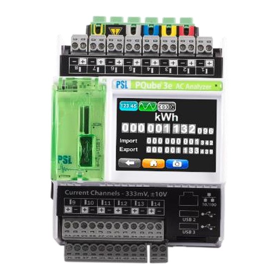
PQube® 3 Power Analyzer
Installation Manual
Revision 3.1
Power Standards Lab
980 Atlantic Ave
© 2008-2019 Power Standards Lab
Alameda CA 94501 USA
www.PowerSensorsLtd.com
Page 1 of 48
Table of
Contents
Previous
Page
Next
Page
1
2
3
4
5
Advertisement
Table of Contents
Need help?
Do you have a question about the PQube 3 Series and is the answer not in the manual?
Ask a question
Questions and answers
Related Manuals for PSL PQube 3 Series
Control Unit PSL PQube 3 User Manual
Rm8 module (13 pages)
Measuring Instruments PSL PQube Installation & User Manual
(113 pages)
Measuring Instruments PSL PQube 3e Installation Manual
Power analyzer (48 pages)
This manual is also suitable for:
Pqube 3e
Pqube 3v
Pqube 3r
Table of Contents
Print
Rename the bookmark
Delete bookmark?
Delete from my manuals?
Login
Sign In
OR
Sign in with Facebook
Sign in with Google
Upload manual
Upload from disk
Upload from URL


Need help?
Do you have a question about the PQube 3 Series and is the answer not in the manual?
Questions and answers