Table of Contents
Advertisement
Quick Links
Download this manual
See also:
Installation Manual
Advertisement
Table of Contents

Summary of Contents for PSL PQube 3
- Page 1 PQube® 3 RM8 Module User Guide Revision 1.0 PQube 3 RM8 Module User Guide v1.0.docx Power Standards Lab, 980 Atlantic Ave, Alameda CA 94501, USA Tel ++1-510-522-4400 Fax ++1-510-522-4455 www.powerstandards.com...
- Page 2 LIMITED TO, THE IMPLIED WARRANTIES OF MERCHANTABILITY AND FITNESS FOR A PARTICULAR USE. PSL shall not be liable for errors contained herein or for incidental or consequential damages in connection with the furnishing, performance, or use of this material. If you do not accept this limitation on liability, please return the product to PSL prior to use.
-
Page 3: Table Of Contents
1. Install the RM8 module onto the DIN rail 2. Slide the PQube 3 and all modules together 3. Make all the voltage and current connections to the PQube 3 4. Install interposing relays to switch high-power loads 5. Connect RM8 relays to an external voltage source 6. -
Page 4: Introduction
• Each RM8 module can control up to 8 individual non-critical loads • Monitors up to two branch circuits with the standard PQube 3, and up to four branch circuits with the PQube 3e. • For each relay, set trigger thresholds based on the power consumption on any given branch circuit. -
Page 5: Overview Of Connections
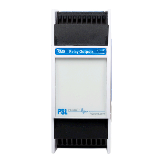
PQube® 3 RM8 Module User Guide Overview of Connections From left to right: R1, R2, R3, R4 From left to right: R5, R6, R7, R8 Specifications Relays Number of relays : 8 (4 on top , 4 on bottom of module) Type : Latching relays Rating :... -
Page 6: Rm8 Module Installation
Read all instructions before installation. NOTE: it is very important that installation of your PQube 3 and associated modules such as the RM8 is performed by qualified personnel in accordance with the local electrical guidelines and codes. The instructions shown here are for the RM8 module only. Refer to the PQube 3 Instruction Manual for wiring instructions for the PQube 3. -
Page 7: Make All The Voltage And Current Connections To The Pqube
PQube® 3 RM8 Module User Guide 3. Make all the voltage and current connections to the PQube 3 3-phase circuit #1, use I1, I2, I3 terminals 3-phase circuit #2, use I6, I7, I8 terminals 3-phase circuit #3, use I9, I10, I 11 terminals (PQube 3e only) 3-phase circuit #4, use I12, I13, I14 terminals (PQube 3e only) The voltage must be common to all circuits. -
Page 8: Connect Rm8 Relays To An External Voltage Source
PQube 3 for use with the RM8 module. Once your PQube 3 has been installed, you will need to configure it for use with the RM8 module. For general device setup, refer to the PQube 3 Instruction Manual. -
Page 9: Assign Labels To Each Branch
PQube® 3 RM8 Module User Guide 2. Assign labels to each branch Go to Load(s) Definition page. Click the 3Ph buttons on the right to enable power calculations and recording for that branch, then add a name for each branch circuit. Page 9 of 13... -
Page 10: Setting Thresholds For Each Relay
PQube® 3 RM8 Module User Guide Setting thresholds for each relay 1. Define threshold, hysteresis, and threshold polarity Go to Relay output page, Relay extension (RM8) tab For each relay (R1 through R8), define the circuit of interest, then set the threshold, hysteresis, and threshold polarity (over-threshold or under-threshold). - Page 11 For circuit #1 an over-threshold (i.e., activates when high) of 10kW and a hysteresis of 2kW is shown. When the power on circuit #1 exceeds 10kW, the PQube 3 will shed the non-critical load on R1. The remaining power on circuit #1 is now 9kW. Your non-critical load will remain disconnected.
- Page 12 PQube® 3 RM8 Module User Guide Example of a wrong hysteresis setting 3kW non-critical load, hysteresis 2kW WARNING: It is imperative that the thresholds are set correctly based on the power consumption of your loads. After shedding a non-critical load, you must ensure that the remaining power remains above your threshold + hysteresis.
-
Page 13: Define Latch Setting And Normal State
2. Define latch setting and normal state Enabling the latch setting forces the state of the relay to persist through a PQube 3 system reboot. When the latch setting is disabled, it will switch to its non-normal state (i.e., alarm state) during the reboot process.


Need help?
Do you have a question about the PQube 3 and is the answer not in the manual?
Questions and answers