Mitsubishi Heavy Industries SC-SL4-AE User Manual
Central control
Hide thumbs
Also See for SC-SL4-AE:
- Technical manual (37 pages) ,
- User manual (31 pages) ,
- Installation manual (7 pages)
Table of Contents
Advertisement
This center console complies with EMC Directive 2014/30/EU, LV
Directive 2014/35/EU, RoHS Directive 2011/65/EU.
CE marking is applicable to the area of 50 Hz power supply.
Cette console centrale est conforme à la directive CEM 2014/30/UE,
à la directive basse tension 2014/35/UE et à la directive RoHS
2011/65/UE.
La marque CE s'applique aux régions alimentées en courant de 50 Hz.
Diese Mittelkonsole erfüllt die Richtlinien zur elektromagnetischen
Verträglichkeit 2014/30/EU, die Niederspannungsrichtlinien
2014/35/EU und die RoHS-Richtlinie 2011/65/EU.
Die CE-Marke gilt für Bereiche mit einer Netzstromversorgung von
50 Hz.
Questa console centrale è conforme alla Direttiva EMC 2014/30/UE,
alla Direttiva LV 2014/35/UE e alla Direttiva RoHS 2011/65/UE.
Il marchio CE è applicabile alla fascia di alimentazione 50 Hz.
Esta consola central cumple con la Directiva de Compatibilidad
Electromagnética 2014/30/UE, con la Directiva de Baja Tensión
2014/35/UE y con la Directiva RoHS 2011/65/UE.
La indicación CE solo corresponde al área de suministro eléctrico de
50 Hz.
Deze centrale console voldoet aan EMC-Richtlijn 2014/30/EU,
LV-Richtlijn 2014/35/EU, RoHS-Richtlijn 2011/65/EU.
CE-markering is van toepassing op het gebied met een netstroom
van 50 Hz.
Esta consola central está em conformidade com a Diretiva EMC
2014/30/UE, a Diretiva LV 2014/35/UE e a Diretiva RoHS
2011/65/UE.
A marca CE aplica-se à zona de fornecimento de energia a 50 Hz.
Αυτή η κεντρική κονσόλα συμμορφώνεται προς την Οδηγία
2014/30/ΕΕ περί ηλεκτρομαγνητικής συμβατότητας , προς την
οδηγία 2014/35/ΕΕ περί χαμηλής τάσης και προς την Οδηγία
2011/65/ΕΕ περί RoHS.
Tο σήμα CE ισχύει μόνον σε περιοχές όπου η τροφοδοσία είναι
50 Hz.
Этот центральный пульт управления соответствует
требованиям директивы по электромагнитной
совместимости 2014/30/EU, директивы по низковольтному
оборудованию 2014/35/EU, директивы RoHS 2011/65/EU.
Маркировка CE нанесена в области источника питания,
работающего на частоте 50 Гц.
Bu orta konsol, 2014/30/EU sayılı EMC Direktifi, 2014/35/EU
sayılı LV Direktifi ve 2011/65/EU sayılı RoHS Direktifi ile
uyumludur.
CE işareti, 50 Hz güç kaynağı için geçerlidir.
Sterownik centralny spełnia wymagania dyrektywy EMC
2014/30/EU, dyrektywy niskonapięciowej 2014/35/EU oraz
dyrektywy RoHS 2011/65/EU.
Oznakowanie CE dotyczy wyłącznie regionów, w których
częstotliwość napięcia zasilającego wynosi 50 Hz.
PJZ012A173
201803
Advertisement
Table of Contents

Related Manuals for Mitsubishi Heavy Industries SC-SL4-AE


Summary of Contents for Mitsubishi Heavy Industries SC-SL4-AE
- Page 1 This center console complies with EMC Directive 2014/30/EU, LV Esta consola central está em conformidade com a Diretiva EMC Directive 2014/35/EU, RoHS Directive 2011/65/EU. 2014/30/UE, a Diretiva LV 2014/35/UE e a Diretiva RoHS CE marking is applicable to the area of 50 Hz power supply. 2011/65/UE.
- Page 2 Thank you for purchasing Central Control ENGLISH SC-SL4-AE, SC-SL4-BE. Before using, read thoroughly this user’s manual for proper operation. After reading, carefully store it for future reference. If any trouble should occur during operation, it will be helpful. Also, read thoroughly the user’s manual which is attached to the air conditioner.
-
Page 3: Table Of Contents
Table of contents Safety Precautions ........3 Maintenance ..........59 Introduction ..........5 Shutdown ............ 60 Overview ............... 5 Using MAINTENANCE MENU ....61 Names and Functions of Parts ........5 Unit Defi nition Settings (SC-SL4-BE only) ....62 Blocks, Groups ............. 6 Outdoor Unit Defi... -
Page 4: Safety Precautions
Safety Precautions • Before starting to use the central control, read these “Safety precautions” carefully to ensure proper operation of the central control. • The safety precautions are classifi ed as “ WARNING ” and “ CAUTION ”. Precautions as shown in the column “ WARNING ”... - Page 5 ❚ OPERATION PRECAUTIONS WARNING If the central control is damaged with If the central control is under abnormal water due to a natural disaster such conditions, stop the operation, turn the as a fl ood or a typhoon, consult your power supply switch off and consult dealer.
-
Page 6: Introduction
Introduction Overview Central controls are made to collectively control air conditioning indoor units. All the controls such as unit monitoring, operation, settings and scheduling can be done on the touch panel. Warning This is a class A product. In a domestic environment, this product may cause radio interference in which case the user may be required to take adequate measures. -
Page 7: Blocks, Groups
Blocks, Groups [Example of Connections] Central control Block 1 Air conditioner Air conditioner Air conditioner Air conditioner Air conditioner Air conditioner Group 1 Group 2 Group Q Block 2 Air conditioner Air conditioner Air conditioner Air conditioner Air conditioner Air conditioner Group Q +1 Group R •... - Page 8 All Groups Display This display appears the fi rst time the unit starts up or when block have not been registered. Make the initial settings in the following order. Time & Date Setting page 40 Group Defi nition page 33 Block Defi...
-
Page 9: Quick Reference Chart For Operations
Quick Reference Chart for Operations Initial settings Date & time Page 40 (Time & Date Setting) Groups Page 33 (Group Defi nition) Blocks Page 37 (Block Defi nition) Viewing status All blocks Page 11 (All Blocks Display) All groups Page 18 (All Groups Display) Each group Page 14 and 17 (Group Operation Settings : BLOCK LAYOUT &... -
Page 10: Menu
Menu When the MENU button is pressed, the screen switches to the one shown below. 1. ALL BLOCKS button 10. CHANGE ALL button Displays a list of the names and status of all Switches the screen for changing group batch blocks in a panel. -
Page 11: Operator Menu Screen
Operator Menu Screen This is displayed when the OPERATOR MENU button is pressed on the MENU screen. page 9 1. BLOCK DEFINITION button 9. LAN SETTING button Switches the BLOCK DEFINITION screen. Switches to the screen used to set the IP page 37 address, subnet mask, and gateway address. -
Page 12: All Blocks Display
All Blocks Display This is displayed when the ALL BLOCKS button is pressed on the MENU screen. page 9 The names and the status of all blocks are displayed in the panels. Unestablished blocks or blocks without any groups are not displayed. If a block button is pressed, the BLOCK LAYOUT screen is displayed. -
Page 13: Changeover Confi Rmation Screen
Changeover Confi rmation Screen This is a screen for confi rming the changes to various settings. The text displayed varies according to the screen called up, but the operation is as follows. Press the YES button to save the settings and to exit. Press the NO button to exit without saving your settings. - Page 14 Unit states The unit status is shown by fi gures. Error stop (One or more units have been stopped because of malfunction.) Please contact your dealer. Demand (The external signal is inputted to the demand terminal.) The target unit’s set temperature shifts by 2 deg C or the target unit will switch to fan mode and remote controller operations are prohibited.
-
Page 15: Operation
Operation Attention A static electric discharge to the unit could cause a break-down. Before performing operations, touch a grounded metal object and discharge any static electricity. Group Operation Settings (Monitor Group Status) Press the ALL BLOCKS button on the MENU screen. page 9 Press the block you wish to set or monitor. - Page 16 <When running and stopping each group> Press the icon of the group for which settings are to be made. The frame turns red. When you want to cancel, please press the icon again. ● To run units Press the RUN button, and press the Yes button on the confi rmation screen. The selected group starts running.
- Page 17 • SET TEMP. Press page 50 (TEMPERATURE RANGE SETTING) • Select (Powerful), (High), (Medium), (Low), or (AUTO), and press the button. – When using automatic mode, valid the AUTO FAN on the FUNCTION SETTING. – When using powerful mode, select 4-speed for FAN TYPE on the GROUP DEFINITION DETAILS screen.
- Page 18 ■ The following method can also be used to set and change operations on each group. <When making settings or changes in the GROUP LIST screen> Press the GROUP LIST button in the BLOCK LAYOUT screen. page 14 [GROUP LIST screen] Press the name of the group for which settings or changes are to be made.
- Page 19 <When making settings or changes in the ALL GROUPS screen> Press the ALL GROUPS button on the MENU. page 9 [ALL GROUPS screen] Press the name for the group to set or change. The group name is reverse highlighted. When the screen switches, the previously selected group name is selected. To change the page, press the button.
-
Page 20: Multiple Groups Operation Settings
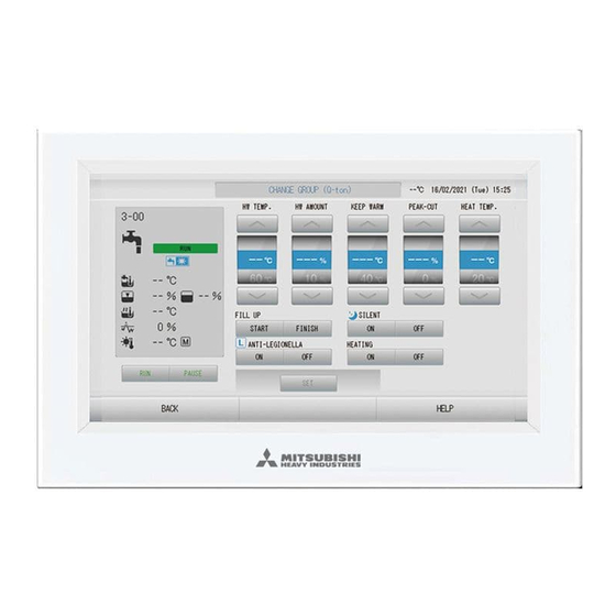
Multiple Groups Operation Settings This section shows how to operate multiple groups in the same block. Press the ALL BLOCKS button on the MENU. page 9 Press the block you wish to set. The BLOCK LAYOUT screen is displayed. [BLOCK LAYOUT screen] 3, 5 <When running and stopping multiple groups>... - Page 21 [CHANGE GROUPS screen] (Individual lock/unlock settings valid in FUNCTION SETTING) This function can be applied to the indoor units, which are the model KXE4 or later, and to the wired remote controller, which is the model RC-E1 or later. Press the button for the item to set or change. •...
- Page 22 • Air direction Select Auto, stop 1, stop 2, stop 3 or stop 4 and press the button. • Lock Press is pressed, remote controller operations are permitted, and if is pressed, they are prohibited. • FILTER RESET If the button is pressed, the fi...
-
Page 23: Group Batch Operation
Group Batch Operation This section shows how to set or change the detailed setting of Batch Operation. Set the groups for batch operation in advance. page 33 Press the CHANGE ALL button on the MENU screen. page 9 [CHANGE ALL screen] (Individual lock/unlock settings valid in MAINTENANCE MENU) This function can be applied to the indoor... - Page 24 • Select (Powerful), (High), (Medium), (Low), or (AUTO), and press the button. – When using automatic mode, valid the AUTO FAN on the FUNCTION SETTING of MAINTENANCE MENU. – When using powerful mode, select 4-speed for FAN TYPE on the GROUP DEFINITION DETAILS screen.
-
Page 25: Schedule Settings
Schedule Settings Operating schedules can be set in group units. Sixteen schedules per day can be registered for operating time (in minutes), run/stop, mode, prohibiting remote controller operations, temperature setting, energy saving and silent mode. Set the detailed daily schedule (weekday, holiday, special 1, special 2) in advance. page 25 ■... - Page 26 <When rewriting the schedule displayed for the current day to detailed daily schedule> Select the detailed daily schedule such as WEEKDAY (green), HOLIDAY (red), SPECIAL 1 (blue) or SPECIAL 2 (yellow) button and press it. Note Set the operating schedule for the detailed daily schedule in advance. page 25 Press the SET button.
- Page 27 ■ Setting a yearly schedule A yearly operating schedule is set on each group. Note As the confi gured settings do not apply to the following year, new confi guration is required for each year. Press the SCHEDULE SETTING button on the MENU screen. page 9 Press the YEARLY SCHEDULE button on the SCHEDULE SETTING screen.
- Page 28 ■ Season Settings Confi gure the mode setting when you have selected “SEASON” mode in the schedule settings. Selecting “SEASON” mode valid you to subsequently change the operating mode and temperature setting collectively at the turn of each season. Press the SCHEDULE SETTING button on the MENU screen. page 9 Press the SEASON SETTING button on the SCHEDULE SETTING screen.
- Page 29 Various screens ■ Select Group screen Press the group name to be selected. The selected group name is reverse highlighted. To change the page, press the PREV or NEXT button. Press the OK button. The selected group can be set. When you do not want to set, press the CANCEL button.
- Page 30 Press the OK button. The prohibited item changes and the screen closes. Press the CANCEL button to cancel the change. If the CLEAR button is pressed, the selected item is deselected. ■ Temperature Setting screen Pressing ▲▼ changes the temperature. Press the OK button.
-
Page 31: Viewing Detailed Unit Information
Viewing Detailed Unit Information The unit numbers and status of each group can be observed. Press the UNIT LIST button in the ALL GROUPS screen ( page 18) or if the UNIT LIST button is pressed in the BLOCK LAYOUT or GROUP LIST screen ( page 14, 17). -
Page 32: Calculating Settings (Sc-Sl4-Be Only)
Calculating Settings (SC-SL4-BE only) ■ Setting the unit defi nition Set the unit defi nition on the MAINTENANCE MENU. page 61 If you want to change the initial settings confi gured at the time of installation, contact your dealer. ■ Setting the period for calculation Press the ACCOUNTING PERIOD TIME button on the OPERATOR MENU screen. - Page 33 Caution The energy consumption calculated by this unit does not conform to OIML, and there are no guarantees concerning the results of the calculations. This unit calculates only energy consumption distribution (gas, electric power). You need to calculate the air-conditioning rates. The calculating data for twelve months are saved.
-
Page 34: Initial Settings
Initial Settings Group Defi nition ■ Selecting the groups to register and display the registered units Press the OPERATOR MENU button on the MENU. page 9 Press the GROUP DEFINITION button on the OPERATOR MENU screen. page 10 [GROUP DEFINITION screen] (Initial GROUP DEFINITION screen) Initial GROUP DEFINITION screen may vary according to the SL communication system. - Page 35 [GROUP DEFINITION DETAILS screen] 8,10 ■ Registering and changing the Group Name being set Press the Group Name. Enter the name for the group. page 42 ■ Adding and deleting units making up the group • When adding units Press an unit address to select the unit from the list of All Units. To change the page, press the button.
- Page 36 Note • By the demand input, it is possible to save on power costs by reducing the power consumption. • When demand input is released, you can set whether or not to conform operation of the unit to nearest schedule before release time of the day. page 71 •...
- Page 37 ■ Saving the settings Press the SET button. Press the Yes button on the confi rmation screen. The group settings are saved. When you do not want to save the settings, press the No button. Note • When you will delete all group defi nition, press the DELETE ALL SETTINGS button and enter your password.
-
Page 38: Block Defi Nition
Block Defi nition Attention Register the group beforehand. page 33 ■ Selecting the blocks to defi ne and displaying the registered groups Press the OPERATOR MENU button on the MENU screen. page 9 Press the BLOCK DEFINITION button on the OPERATOR MENU screen. page 10 [BLOCK DEFINITION screen] (Initial BLOCK DEFINITION screen) - Page 39 ■ Adding and deleting groups registered in a block • When adding groups Press the group name to select the group from the list of All Groups. When changing the page, press the button. Press the ADD button. The selected group is added to the group entry list and deleted from the list of All Groups. •...
- Page 40 Press the OK button. Selected layout displays. ■ Arranging icons Press group icon. Red outline shows that the group is selected. Press an area to move the group icon. The group icon moves. Note You can’t arrange icons for default layout. ■...
-
Page 41: Time & Date Setting
Time & Date Setting Press the MENU button and then press the OPERATOR MENU button. page 9 Press the TIME & DATE SETTING button on the OPERATOR MENU screen. page 10 [TIME & DATE SETTING screen] <When setting current time> Press the Day, Month, Year, Hour and Min buttons. - Page 42 <When setting the detail of time (time zone, NTP or summer time)> Press the DETAILS button. TIME & DATA SETTING DETAILS screen is displayed. • Time Zone Press Time Zone. Time Setting screen is displayed. Input time difference from UTC (Universal Time, Coordinated).
-
Page 43: Convenient Functions
Convenient Functions Entering Numbers and Characters ■ Entering numbers Press the button of the numerical value to input. BS button : backspaces. (Deletes one number.) CLEAR button : clears the input. (Deletes all numbers.) Press the OK button. The number is changed and the screen closes. Press the Cancel button to cancel the change. -
Page 44: Display Setting
Display Setting The brightness and backlight timeout settings can be confi gured, and the mode can be switched to screen cleaning. When changing the settings, take the following steps. Press the DISPLAY SETTING button on the MENU screen. page 9 [DISPLAY SETTING screen] Select the Brightness using the buttons. -
Page 45: Corrections For Power Outage
Corrections for Power Outage ■ Data retained during a power outage • Each settings by SL4 (except fl ap control) • Each data by SL4 before a power outage ■ Data lost at a power outage • Operating and setup status of each indoor unit before a power outage (including operating mode, temperature setting, and remote controller permit/prohibit setting) •... - Page 46 Transferring Monthly Data It is convenient if folders are created in the USB memory in advance. Press the EXPORT MONTHLY DATA FILES button on the OPERATOR MENU. Press the “EXPORT MONTHLY DATA FILES to USB” button. Select the folder on the Folder Selection screen. [Folder Selection screen] Press the folder to be selected.
-
Page 47: Operation Time History
Operation Time History The OPERATION TIME HISTORY screen displays a graph showing the accumulated daily operation time for 31 days by the group. Press the OPERATION TIME HISTORY button on the MENU screen. page 9 Select a group. Select a group for which you want to view the accumulated operation time. Press a group to select. -
Page 48: Energy Consumption History (Sc-Sl4-Be Only)
Energy Consumption History (SC-SL4-BE only) Press the ENERGY CONSUMPTION HISTORY button on the OPERATION TIME HISTORY screen. page 46 [ENERGY CONSUMPTION HISTORY screen] Select a group. Select a group for which you want to view the accumulated consumption. Press a group to select. The selected group is displayed. Select ELECTRIC or GAS. -
Page 49: Lan Settings
LAN Settings You can set the IP address, subnet mask and gateway address of the central control. Press the LAN SETTING button on the OPERATOR MENU screen. page 10 Setting and viewing the IP Address (Factory default: 192.168.0.120) Specify the IP address of the central control. Press an IP address to set. -
Page 50: Operator Settings
Operator Settings Specify the ID, password of the operator. Press the OPERATOR SETTING button on the OPERATOR MENU screen. page 10 Setting and viewing the ID Specify the operator’s ID. Press ID to input an ID. The input ID is displayed. Setting and viewing the Password Specify the password of the central control. -
Page 51: Function Setting
Function Setting You can set temperature range, energy saving setting, auto switch setting and home leave setting. When the FUNCTION SETTING button is pressed on the OPERATOR MENU screen, FUNCTION SETTING screen is displayed. 1. TEMPERATURE RANGE SETTING 3. HOME LEAVE SETTING You can set upper or lower limit of temperature You can set the temperature and fan speed for setting. -
Page 52: Control Function Setting
Press Upper/Lower limit (°C) of SET TEMP. in Heating. Select temperature by pressing button, and press OK button. If you do not want to make the setting, press the cancel button. Setting temperatures can be set in the following ranges. Lower limit value Upper limit value Cool/Dry/Auto... -
Page 53: Home Leave Setting
Press Shift SET TEMP. (°C) in HEAT Mode of Energy saving Setting. You can set the shift value of set temperature in heat mode of energy saving setting. Note Energy saving : The set temperature of the air conditioner shifts by 1 to 3 deg C (+1 to 3 deg C in cooling or dry mode, or -1 to 3 deg C in heating mode), and remote control set temperature operation is prohibited. - Page 54 Press Set TEMP. (°C) in COOL Mode of home leave. You can set the indoor temperature in cooling. Select Fan Speed in COOL Mode of home leave. You can set the fan speed in cooling mode. Press Switching Outside TEMP. (°C) in HEAT Mode of home leave. You can set the outdoor temperature to judge the operation mode in heating.
-
Page 55: Data Logging
Data Logging You can record the units’ data (run/stop, set temperature, return air temperature for all indoor units and outdoor air temperature for selected outdoor units) of previous month or present month page 63. Press the DATA LOGGING button on the OPERATOR MENU. <When saving units’... -
Page 56: Flap Control Setting
Flap Control Setting Motion range (upper and lower limit positions) of the fl ap at each air outlet can be set at a desired range individually. Caution When changing contents of the individual fl ap control, stop the air conditioner. Press FLAP CONTROL SETTING button on the OPERATOR MENU. -
Page 57: Group User Setting
Group User Setting Press the GROUP USER SETTING button on the OPERATOR MENU screen. page 10 ■ Selecting the group user to register and display the registered groups Press a group user name. When adding a group, press an empty group name area. When changing the settings for a registered group name, press that group user name. - Page 58 ■ Adding and deleting units making up the group • When adding groups Press a group name from the list of All groups. When changing the page, press button. Press the ADD button. The selected group is added to the list of Group Entry and deleted from the list of All Groups.
-
Page 59: Viewing Alarm History
Viewing Alarm History Press the ALARM HISTORY button on the OPERATOR MENU screen. page 10 Check the content on the ALARM HISTORY screen. Press the OPERATOR MENU button. It returns to the OPERATOR MENU screen. Note The data is erased when rebooting or power outage. System Information The version of the Air-Conditioners Management System being used can be confi... -
Page 60: Maintenance
Maintenance Wipe with a soft, dry cloth to clean. When it is very dirty, excluding the touch panel, use a neutral cleanser dissolved in warm water to wipe it off and afterwards wipe that off with clean water. Caution Do not use paint thinner, organic solvents or strong acids. The color may change and the paint may be removed. -
Page 61: Shutdown
Shutdown The con rmation screen is displayed after the SHUTDOWN button is pressed on the MENU screen and enter your password. page 9. When you press the Yes button, the screen switches to the one shown below (a). Please wait until you get the message that shows “Please switch off the power supply.” When you do not turn the power off, press the No button. -
Page 62: Using Maintenance Menu
Using MAINTENANCE MENU The MAINTENANCE MENU is provided for dealers and qualifi ed professionals responsible for maintaining the central control units. When logging in with a normal operator’s ID, you are not permitted to operate the MAINTENANCE MENU. This screen is displayed when the MAINTENANCE MENU button is pressed on the MENU screen. page 9 1. -
Page 63: Unit Defi Nition Settings (Sc-Sl4-Be Only)
Unit Defi nition Settings (SC-SL4-BE only) Press the UNIT DEFINITION button on the MAINTENANCE MENU screen. page 61 Press the item to be set or changed on the list. Each time the “TYPE” item is pressed, the unit type changes. MULTI1 : calculating according to the amount of refrigerant fl... -
Page 64: Outdoor Unit Defi Nition
Outdoor Unit Defi nition You can choose up to 3 outdoor units for outdoor air temperature. Press the OUTDOOR UNIT DEFINITION button on the MAINTENANCE MENU screen. <When adding units> Press directly an outdoor unit address in the list of All Outdoor Units. To change the page, press the button. -
Page 65: Import/Export Confi Guration File
Import/Export Confi guration File Press IMPORT/EXPORT CONFIGURATION button on the MAINTENANCE MENU screen. Attention • Be sure to perform these operations after inserting the USB memory into the unit. page 5 • Please do not operate while the display light of the USB memory is blinking fast. You may perform your operations or remove the USB memory only when the display light is blinking slowly. - Page 66 Press the OK button. A confi rmation screen (Defi nition fi le backup confi rmation screen) is displayed. Press the “OK” button on either of the screens. Note If the CANCEL button is pressed, it returns to the previous screen. <Importing Confi...
-
Page 67: Meter Defi Nition (Sc-Sl4-Be Only)
Meter Defi nition (SC-SL4-BE only) Meter group defi nition fi le and pulse constant defi nition fi le are needed for energy consumption history. Press the METER DEFINITION button on the MAINTENANCE MENU screen. Insert the USB memory and press the IMPORT button. Select the folder on the Folder Selection screen. -
Page 68: Maintenance User Setting
<When saving the data> Press the EXPORT CSV FILE button. The data of selected units is saved. Maintenance User Setting Set the ID, password, of the maintenance user. Press the MAINTENANCE USER SETTING button on the MAINTENANCE MENU screen. Setting and viewing the ID Specify the maintenance user’s ID. -
Page 69: Function Setting
Function Setting You confi gure SL mode, valid/invalid setting of auto mode, auto fan, remote controller lock/unlock and external input setting and so on. By pressing FUNCTION SETTING button on the MAINTENANCE MENU screen, FUNCTION SETTING screen is displayed. 1. SL MODE 3. -
Page 70: Sl Mode
SL Mode Confi gure the Superlink communication system setting. (Factory default: New) Incorrect setting of SL mode cannot establish communication with some or all air conditioner. Press FUNCTION SETTING button on the MAINTENANCE MENU screen. Press SL MODE button on the FUNCTION SETTING screen. ●... -
Page 71: Function Settings Details
Function Settings Details You can confi gure the valid/invalid setting of auto mode, auto fan and remocon lock/unlock. Press FUNCTION SETTING button on the MAINTENANCE MENU screen. Press FUNCTION SETTING DETAILS button on the FUNCTION SETTING screen. Temp. Indication (Factory default: °C) This selects Fahrenheit or Celsius for the temperature display. -
Page 72: External Input Settings
External Input Settings Press FUNCTION SETTING button on the MAINTENANCE MENU screen. Press EXTERNAL INPUT SETTING button on the FUNCTION SETTING screen. Select 1, 2 or 3 for External Input Function. (DI1:Emergency Stop) Demand 1 Demand 2 Demand Account Time Account Time 1 Account Time 2 Note... -
Page 73: Language Setting
Language Setting Press the LANGUAGE SETTING button on the MAINTENANCE MENU. <When changing the language for display> Select the language. The display language is set to the language which you select. Press the SET button. Press the “YES button” on the confi rmation screen. The setting applies after reboot. -
Page 74: Factory Clear
Factory Clear Press the FACTORY CLEAR button on the MAINTENANCE MENU screen. 1. INITIALIZE TO FACTORY SETTING 3. INITIALIZE SCHEDULE SETTINGS This resets the settings to factory default This initializes schedule data. except time & date setting ( page 40) 4. -
Page 75: Viewing Alarm History
Viewing Alarm History Press the ALARM HISTORY button on the MENTENANCE MENU screen. page 58 Check the content on the ALARM HISTORY screen. <Deleting an alarm history item> Press the date to be deleted. The date is highlighted. Press and change the content. Press the DELETE button. -
Page 76: External Input Status
External Input Status Press the EXTERNAL INPUT STATUS button on the MAINTENANCE MENU screen. • External Input The statuses of emergency stop, demand and accounting time contact can be checked. • Pulse Counter The accumulated number of pulse inputs (eight points) of the current day can be checked. –... -
Page 77: Troubleshooting
Troubleshooting “Each group status display” is A malfunction has occurred with the unit. The malfunctioning unit is displayed in red stopped. Contact your dealer. The shop will need the following information: “Each group status display”, “malfunction situation”, “model name of the malfunctioning unit”, “Error No. - Page 78 “USB memory was not found.” The USB memory may not have been fully inserted. Remove the message appears. USB memory, and reinsert it. If this message appears again, it is possible that the USB memory is damaged or the USB memory is not the attachment.
- Page 79 Caution Caution that performing of the monthly calculation (SC-SL4-BE only) • This center console does not warrant the contents of the calculation result. Please be sure to use a calculation result in the customer’s responsibility. We are not liable for any damages whatsoever (including but not limited to damages for loss of business profi...
-
Page 80: Installation
Installation Do not install the central Do not install the central Avoid any place which is control in any area where control in any area where it is exposed to direct sunlight or noise easily generates. very humid or the vibration is is near a heat source.
Need help?
Do you have a question about the SC-SL4-AE and is the answer not in the manual?
Questions and answers