
Related Manuals for McElroy TracStar 28 2 Auto Series

Summary of Contents for McElroy TracStar 28 2 Auto Series
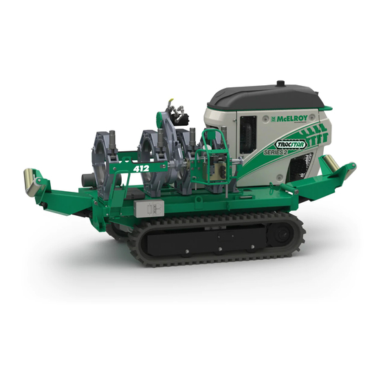
- Page 1 Operator’s Manual ® TracStar 28/250 412/618 Series 2 Auto Fusion Machines Original Language: English Manual: T1829801 Revision: B 03/19...
- Page 2 This product and other products could be protected by patents or have patents pending. All the latest patent information is available at patent.mcelroy.com...
- Page 3 TX05273-03-28-17 McElroy University For more than 30 years, McElroy has been the only pipe fusion machine manufacturer to continuously offer advanced training. Course offerings are meant to enhance your efficiency, productivity and safety in the proper use of McElroy machines.
- Page 4 McElroy or has become damaged McElroy reserves the right to make any changes in or due to misuse, negligence or casualty, or has not been improvements on its products without incurring any operated or maintained according to McElroy’s printed...
-
Page 5: Table Of Contents
Pendant Computer Interface....... . 2-9 COPYRIGHT © 2018, 2017 McELROY MANUFACTURING, INC. Tulsa, Oklahoma, USA All rights reserved All product names or trademarks are property of their respective owners. - Page 6 Table of Contents Operation Read Before Operating ........3-1 Check Hydraulic Fluid Level .
- Page 7 Table of Contents Lifting Lifting Safety ......... . 8-1 Lift Fusion Machine.
-
Page 8: Safety
Follow all applicable federal, state, local, and industry specific regulations. McElroy Manufacturing, Inc. cannot anticipate every possible circumstance that might involve a potential hazard. The warnings in this manual and on the machine are therefore not all inclusive. -
Page 9: General Safety
Safety General Safety Safety is important. Report anything unusual that you notice during set up or operation. LISTEN for thumps, bumps, rattles, squeals, air leaks, or unusual sounds. SMELL odors like burning insulation, hot metal, burning rubber, hot oil, or natural gas. FEEL any changes in the way the equipment operates. -
Page 10: Units With Engines
Safety Units With Engines Combustion engines can cause explosions when operated in an explosive atmosphere. Do not operate gas or diesel powered machines in an ¡PELIGRO! explosive atmosphere. When operating in an explosive atmosphere, keep vehicle in a safe area by using hydraulic extension hoses to the carriage. Help prevent fires by keeping machine clean of accumulated trash, debris and facer shavings. -
Page 11: Pipe Handling Safety
Safety Pipe Handling Safety Do not position yourself or any other personnel under supported or raised pipe. Pipe is heavy and could fall unexpectedly. ¡ATENCIÓN! Pipe that is bent can store a great amount of energy. Do not bend and force the pipe into the machine. A bent pipe with stored energy can generate ¡ATENCIÓN! tremendous force when that energy is released. -
Page 12: Electrical Safety
Safety Electrical Safety Always ensure equipment is properly grounded. It is important to remember that you are working in a wet environment with electrical devices. Proper ¡ATENCIÓN! ground connections help to minimize the chances of an electric shock. Frequently inspect electrical cords and unit for damage. Have damaged components replaced and service performed by a qualified electrician. -
Page 13: Units With Hydraulics
Safety Units With Hydraulics It is important to remember that a sudden hydraulic oil leak can cause serious injury, or even be fatal if the pressure or oil temperature is high enough. Escaping fluid under pressure can penetrate the skin causing serious injury. Keep hands and body away from pinholes which ¡ATENCIÓN! eject fluid under pressure. -
Page 14: Heater Is Hot
Safety Heater Is Hot The heater is hot and will burn clothing and skin. Keep the heater in its insulated heater frame or stand when not in use, and use care when heating the pipe. ¡CUIDADO! NOTICE: Use only a clean dry lint free non-synthetic cloth to clean the ОСТОРОЖНО... -
Page 15: Overview
Overview Theory of Heat Fusion The principle of heat fusion is to heat two pipe surfaces to a designated temperature, and then fuse them together by application of force. This develops pressure which causes flow of the melted materials, which causes mixing and thus fusion. When the thermoplastic material is heated, the molecular structure is transformed into an amorphous condition. -
Page 16: Carriage Assembly
Overview Carriage Assembly The carriage assembly consists of two fixed jaws and two hydraulically operated movable jaws. The carriage assembly can be removed from the machine for remote operation. An optional extension kit is required when using the carriage remotely. The outer fixed jaw can be removed to allow more area to fuse tees or perform tie-ins easier. -
Page 17: Diesel Engine
Overview Diesel Engine Read the operating and maintenance instructions for the engine before operating. The engine is a 3 cylinder water cooled design. It uses an electric fuel pump located near the fuel tank. The throttle control and key switch are at the rear of the machine. -
Page 18: Battery Disconnect Switch
Overview Battery Disconnect Switch The battery disconnect switch removes the battery power to the system. TX05161-09-22-16 Hydraulic Fluid Reservoir The hydraulic fluid reservoir is located above the engine. Refer to the "Hydraulic Fluids" section of this manual for hydraulic fluid recommendations. TX02322-02-27-14 Hydraulic Fluid Filter This machine is equipped with a 10 Micron filter on the return... -
Page 19: Facer
Overview Facer The facer is a rotating planer-block design. The blade holders each contain blades and are chain driven (enclosed in lubricant) by a hydraulic motor. There are facer stops that allow for a specific amount of faced pipe to protrude from the jaws. When needed for off-vehicle modular operation, the facer can be removed from its carriage skid-mounted pivot arm. -
Page 20: Power For Heater
Overview Power for Heater The heater cord plugs into the receptacle on the frame. There is a voltage meter above the receptacle that displays the output voltage. TX05289-04-12-17 Insulated Heater Stand/Shroud The heater should always be stored in the insulated heater stand, heater shroud or blanket for protection of the operator and to minimize heat loss and risk of mechanical damage. -
Page 21: Battery Charging Connection
Products SB175 connector. TX05165-04-06-17 ® The Coach McElroy Fusion Control Pendant The fusion control pendant is the operator interface for machine fusion controls and is used to control pressures and times to meet selected fusion standards. The control pendant is equipped with a handheld computer which operates the fusion control system program. -
Page 22: Pendant Handheld Computer
Overview Pendant Handheld Computer The handheld computer is a compact and rugged computer mounted to the pendant base and connected using a serial cable and the power cable. The computer has a display with function keys below the display that are used to operate the installed software. -
Page 23: Pendant Computer Interface
Overview Pendant Computer Interface The pendant computer software controls and logs the fusion process. Wi-Fi icons: Software No connectivity Audio Version Establishing connection to Wi-Fi Connected Carriage Heater Temperature Pressure Displays 999°F when there is a heater fault in the heater or heater control system. - Page 24 The DataLogger® Vault™ is a software application from McElroy that provides joint data storage and analysis at no cost to users of the Coach McElroy Fusion Control Pendant. The DataLogger Vault is a secure, online application that allows users to view and analyze their joint data from almost any device, from almost any location. All that is needed is a device such as a PC, Mac, smartphone, tablet, etc.
-
Page 25: Read Before Operating
Operation - General Read Before Operating Before operating this machine, please read this manual thoroughly and keep a copy available for future reference. Return manual to the protective storage box when not in use. This manual is to be considered part of your machine. TX00401-9-15-94 Check Hydraulic Fluid Level Check fluid level in the reservoir and verify that fluid is visible in... -
Page 26: Moving Machine Into Position
Operation - General Moving Machine Into Position Make sure all personnel are safely clear of the machine before moving. Stand behind the machine console. Move both track control levers forward to go in a straight line. Release the levers to stop. Moving just the right track forward turns the machine to the left. -
Page 27: Install Clamping Inserts
Operation - General Install Clamping Inserts Select and install appropriate clamping inserts for the pipe that is being fused. Clamping inserts are required for all sizes except sizes that match the size of the jaw without inserts. TX02956-4-15-09 Loading Pipe Into Machine Clean the inside and outside of pipe ends that are to be fused. -
Page 28: Positioning Pipe In Machine
Operation - General Positioning Pipe In Machine Swing the facer into place. With the carriage control valve lever, move the carriage toward the fixed jaws, while watching the gap at each end of the facer rest buttons. When the pipe is in contact with the facer, this gap indicates the amount of material that will be trimmed from the pipe end. -
Page 29: Begin Facing
Operation - General Begin Facing Turn facer on by opening valve (A) on top of the facer. Move the pressure selector control (B) to the top (facing pressure) position. The facing pressure should be set as low as possible while still facing pipe. -
Page 30: Check Alignment
Operation- General Check Alignment Move carriage to the left at facing pressure, until pipe ends contact. Look across the top surface of pipe ends to check alignment. If there is a HI/LO misalignment between pipe ends, adjustments must be made. If HI/LO alignment is acceptable, proceed to "Check for Slippage". -
Page 31: Completing The Fusion Operation
Operation - General Completing the Fusion Operation The fusion operation can be completed by automatic fusion or by semi-auto fusion. Automatic Fusion: The machine automatically performs all carriage movements to complete the fusion operation. Refer to section "Operation - Auto Fusion" for instructions on completing an auto fusion. -
Page 32: Operation - Auto Fusion
Enter a McElroy ID, if applicable, or tap the bar code symbol to turn on the bar code scanner and scan the bar code on the McElroy operator qualification wallet card. - Page 33 Operation - Auto Fusion Auto Fusion (continued) Identifications: Confirm if the identifications entered are correct. These identifications will be displayed in the joint report. • Press to change the identifications (System password may be required). • Tap Yes>> to proceed with these identifications and proceed to "Parameters". To Change the Identifications: •...
- Page 34 Operation - Auto Fusion Auto Fusion (continued) • Input a job number. • Tap Enter>>. • Input a joint number. The joint number will increment up as fusion joints are completed. • Tap Enter>>. Parameters: Confirm if the parameters listed are correct. These parameters will be displayed in the joint report.
- Page 35 Operation - Auto Fusion Auto Fusion (continued) • Input the ambient temperature. The temperature will be recorded in the units the device is set to in the system menu. • Input the pipe material. • Tap Enter>>. • Input the pipe size and use the up/down arrows to select the appropriate units.
- Page 36 Operation - Auto Fusion Auto Fusion (continued) Enter any location or project details (optional). These details will be displayed in the joint report. • Press to change the location/project details. • Tap Yes>> to proceed with these location/project details. Prepare for Fusion: Refer to "Operation - General"...
- Page 37 Operation - Auto Fusion Auto Fusion (continued) The auto fusion operation will start and proceed through a series of screens. The carriage will move automatically. There will be audible beeping before the carriage moves automatically. Hydraulically operated equipment operates under high pressure and generates extremely high forces.
- Page 38 Operation - Auto Fusion Auto Fusion (continued) Self retracting heaters will remove automatically during the heater removal process. Quickly Remove Heater After the fusion joint, the joint report will appear. TX05269-04-16-18 4 - 7...
-
Page 39: View Joint Report
Passport/EUSR: - Number for UK gas reference. McElroy ID: - ID number given to McElroy qualified operators. Machine ID: - Identification number for the fusion machine. Machine Model: - Fusion machine model used to perform the fusion. - Page 40 Operation - Auto Fusion Auto Fusion (continued) 21 Computer: - The handheld computer serial number. 22 Software: - The software version number. 23 Firmware: - The Fusion Control Pendant firmware number. 24 GPS: - The GPS coordinates recorded for the fusion joint. Tap the GPS icon to acquire GPS coordinates if none have been recorded.
- Page 41 Operation - Auto Fusion Auto Fusion (continued) After the entering notes and a photo, the joint report is sent to the DataLogger® Vault™ if a Vault account is logged into and a data connection is available. If not, the joint report is saved on the handheld computer for transfer at a later time.
-
Page 42: Create Dummy Joint (Optional)
Operation - Auto Fusion Auto Fusion (continued) Create Dummy Joint (Optional): A Dummy Joint can be made by following the normal facing, heating, and soaking procedures. Any time during the soak cycle, you may tap <<Abort to interrupt the cycle. The automatic cycle will stop, and you are given a choice to abort the joint or record a Dummy Joint report. -
Page 43: Opening Jaws
Operation - Auto Fusion Opening Jaws After the fusion process is complete, ensure the carriage directional control to the neutral position. Loosen all clamp knobs, and move carriage to the right far enough to open the jaw nearest the facer. Self Retracting Heater: Facer will be positioned between the movable jaws. -
Page 44: Auto Report Menu
Operation - Auto Fusion Auto Report Menu • View Report: - Opens the lists of joint reports that are not sent and sent to the DataLogger® Vault™. • Send Reports: - Sends any joints not sent to the DataLogger® Vault™. Requires a data connection. - Page 45 • Registered... - Displays a log in screen with user name and password fields. Log in using a registered account. If you do not have a registered account, go to vault.mcelroy.com to create a new account. • Delete... - Logs out of the DataLogger Vault and deletes the personal information attached to the registered account from the handheld computer.
-
Page 46: Operation - Semi-Auto Fusion
Operation - Semi-Auto Fusion Semi-Auto Fusion Semi Auto fusion allows the operator to perform all fusion operations to make a manual fusion using the Fusion Control Pendant. • Tap Semi-Auto to manually set the fusion operation pressures. IMPORTANT: The Operation - General section must be completed before starting a semi-auto fusion. -
Page 47: Check For Slippage
Operation - Semi-Auto Fusion Check for Slippage Bring the two sections of pipe together under fusing pressure to make sure they don’t slip in the jaws. If slippage occurs, return to Loading Pipe into Machine. TX00971-04-18-16 Set Temperature Tap the Temperature button and input the desired temperature setting. -
Page 48: Heat Pipe
Operation - Semi-Auto Fusion Heat Pipe Follow the pipe manufacturer's or joining standard's suggested heating procedure. IMPORTANT: A modified shift sequence may be required in certain situations. Shift the pressure selector control to the fusing position and move carriage to the left to bring pipe ends in contact with the heater. Ensure proper initial bead-up, move pressure selector control to middle (heating) position. -
Page 49: Opening Jaws
Operation - Semi-Auto Fusion Opening Jaws After the fusion process is complete, Shift the carriage directional control to the neutral position. Loosen all clamp knobs, and move carriage to the right far enough to open the jaw nearest the facer. Self Retracting Heater: Facer will be positioned between the movable jaws. -
Page 50: System Menu
The fusion machine is equipped with The Coach Fusion Control ® System on the McElroy fusion pendant. The fusion control software settings can be changed through the system menu. Tap System Menu to make changes to the fusion control software. -
Page 51: System Menu (2)
System Menu System Menu (1) Set Date and Time: There are two clock locations, home and visiting. Set the time zone, time, and date for home time to use with the machine. Select the alarms tab at the bottom of the screen to tab to the alarm settings. -
Page 52: System Menu (3)
System Menu System Menu (1) (continued) Change Password: To change the password: Input the current system password. The default system password is 123. Tap Enter>>. Input the new system password. Tap Enter>>. Re-input the new system password. Tap Enter>>. 6 - 3... -
Page 53: System Menu (4)
System Menu System Menu (1) (continued) Change Heater Offset: Input the measured offset value in degrees: If the measured surface temperature differs from the temperature display on the handheld computer, enter the difference between the measured surface temperature and the displayed temperature on the handheld computer by adding the difference to the previously entered heater offset. -
Page 54: System Menu (5)
System Menu System Menu (3) • Tap Invert Carriage Direction to invert the direction of movement of the carriage control. • Tap Ignore Heater to ignore the heater reaching fusion temperature to allow the operator to proceed through the fusion processes that are dependent on heater temperature. - Page 55 System Menu System Menu (4) (continued) Check Fema Voltage: The FEMA pressure valve voltage can be temporarily changed for testing and troubleshooting purposes. The voltage is entered in millivolts (mV). Setting the voltage will show a response in the hydraulic pressure. Enter a value between 1000mV to 10,000mV. Press the Windows ®...
- Page 56 System Menu System Menu (4) (continued) Check RTD and GFCI: Check values for the RTDs and GFCI. Press Left navigation key to rezero/calibrate the RTDs Press Right navigation key to clear the GFCI error count. Left Navigation Right Navigation TX05082-06-28-16 System Menu (5) Update Software: Updates the software if there is a newer version available (a data...
-
Page 57: Special Operations
Special Operations Special Operations Overview The carriage may be used off the vehicle for in-ditch tie-ins and fusing tees or fittings that require more working space than is possible while the carriage is mounted on the vehicle. All off vehicle operations require the extension kit which includes extension cables and hoses. -
Page 58: 4-Jaw Carriage Removal
Special Operations 4-Jaw Carriage Removal There are two sets of hydraulic hoses. One set connects to the carriage hoses on the machine and to the carriage. The other set connects to the facer hoses on the machine and to the facer. Disconnect both sets of hoses and transducer cable. - Page 59 Special Operations 4-Jaw Carriage Removal (continued) The outrigger is an arm that is retractable and adds support to the carriage assembly when opening the jaws and pivoting the facer away from the carriage. To extend or retract the outrigger, press the locking button near the base of the outrigger and push or pull the arm until the button snaps to the locked position.
-
Page 60: Outer Fixed Jaw Removal
Special Operations Outer Fixed Jaw Removal The outer fixed jaw can be removed to allow more room to fuse tees or perform tie-ins. Remove both fixed jaw braces (A). Loosen 2 bolts (B) on the jaw and remove the jaw. The pipe lift control bracket (C) can be loosened and rotated down from the vehicle to allow clearance to fuse without the outer fixed jaw on the machine. -
Page 61: 3-Jaw Carriage Removal
Special Operations 3-Jaw Carriage Removal Carriage Removal There are two sets of hydraulic hoses. One set connects to the carriage hoses on the machine and to the carriage. The other set connects to the facer hoses on the machine and to the facer. Disconnect both sets of hoses. -
Page 62: Top Loading Facer
Special Operations Top Loading Facer TracStar® 412 and 618 Facer Removal Remove rear guide rod bracket. Support the facer with a person or sling so it does not fall once the facer locking bolts are removed. Remove facer locking bolts. Lift facer out of the carriage and set on cardboard or wood blocks off of ground. - Page 63 Special Operations Top Loading Facer (continued) TracStar® 28 and 250 Facer Removal Loosen facer locking bolt. Lift facer out of the carriage and set on cardboard or wood blocks off of ground. Remove rear guide rod bracket. Attach rear guide rod bracket in the position shown. 7 - 7...
-
Page 64: Remove Upper Jaws
Special Operations Top Loading Facer (continued) Manual Facer Operation The machine components are heavy. Using one person to lift the facer or carriage may result in an injury. Use a lifting strap and an overhead ¡CUIDADO! lifting device to lift facer or carriage. For manual lifting, two people are required to lift the facer or ОСТОРОЖНО... -
Page 65: Make Fusion Joint
Special Operations Make Fusion Joint Clamp Carriage Assembly to Pipe Position carriage assembly on side of the pipe. Lift pipe and slide carriage assembly under pipe. Rotate carriage assembly around to a normal upright position. Attach the top jaws and loosely clamp around pipe. 7 - 9... - Page 66 Special Operations Make Fusion Joint (continued) Attach Hydraulic Hoses There are two sets of hydraulic extension hoses. One set connects to the carriage hoses on the machine and to the carriage. The other set connects to the facer hoses on the machine and to the facer.
-
Page 67: Lifting
Lifting Lifting Safety Follow all applicable federal, state, local, and industry specific regulations when lifting. Safety warnings: ¡ATENCIÓN! Do not exceed rated load or lift loads greater than the rated load of the lifting device. Do not operate a damaged or malfunctioning lifting device. Do not lift persons. -
Page 68: Lift Fusion Machine
Lifting Lift Fusion Machine The sling has equal length cables, attach the sling to the three lifting points. The cable attached at position (A) will run between the moveable jaws of the carriage. Move the carriage so that the cable does not come into contact with the jaws when lifting. Lift fusion machine. -
Page 69: Maintenance
Maintenance Preventative Maintenance To insure optimum performance, the machine must be kept clean and well maintained. With reasonable care, this machine will give years of service. Therefore, it is important that a regular schedule of preventive maintenance be kept. Store machine inside, out of the weather, whenever possible. TX00428-8-10-95 Washing the Machine Cover plugs and electrical control boxes before washing. -
Page 70: Remove Cowlings
Maintenance Remove Cowlings To Remove Side Cowlings: Flip up the ring on the fasteners (A) and turn them 90° to release. Remove the cowling. To Remove Front Cowlings: Loosen and remove the nuts (B) that attach the cowling to the machine. Remove the cowling. To Remove Back Cowling: Loosen the nuts (C) and slide the bottom of the cowling out and then slide the cowling down out of the machine. -
Page 71: Setting Engine Speed
Maintenance Setting Engine Speed With the engine running at max speed plug the heater in. Check the voltmeter above the heater receptacle. Adjust throttle cable sheath until voltage is correct. The voltmeter should read 240V±5. When the engine speed is adjusted, the hydraulic flow rate needs to be checked to verify it is within range. -
Page 72: Bleeding Air From Hydraulic System
Maintenance Bleeding Air From Hydraulic System The two carriage cylinders have air bleed screws and must be bled if the system ever runs low on oil or leaks air on inlet side of pump. Air in the system is indicated when carriage movement becomes jerky and erratic. To bleed the system, proceed as follows: The bleed plugs are on the cylinder glands. -
Page 73: Check/Add Antifreeze
Maintenance Check/Add Antifreeze Add antifreeze in a 50/50 mix with water as needed. Replace antifreeze mixture once each year or as recommended in engine manual. TX05183-09-22-16 Facer Blades Ensure the machine is off. Facer blades are sharp and can cut. Never attempt to remove shavings while the facer is running, or is in the facing position between the jaws. -
Page 74: Installing Butt Fusion Heater Plates
Maintenance Installing Butt Fusion Heater Plates Install butt fusion heater plates while the heater is cool. The heater is hot and will burn clothing and skin. Keep the heater in its insulated heater stand or frame when not in use, and use care when heating the pipe. ¡CUIDADO! Butt fusion heater plates are installed with stainless steel cap screws. -
Page 75: Clean Jaws And Inserts
Maintenance Clean Jaws and Inserts Ensure the machine is off and disconnected from power source. To prevent slippage and insure proper alignment, the jaws and insert serrations must be clean. Clean the jaws and inserts of any dirt or residual material using a stiff-bristled brush. -
Page 76: Battery Replacement And Charging
Maintenance Battery Replacement and Charging Remove the vehicle deck cover. The battery for the vehicle is under the cover below the deck of the vehicle. Disconnect the battery by removing the negative (black) cable first and then remove the positive (red) cable. To remove the battery, remove the bolt (A) and remove the battery holders. -
Page 77: Install Sim Card
Maintenance Install SIM Card The handheld computer has the capability to use a SIM card for a data connection. A SIM card can be purchased through a cellular carrier. The Trimble® Nomad handheld computer uses GPRS, Edge, or 2.5G SIM cards. Turn the computer to the back and remove the 4 screws (A) from the back cover and remove. - Page 78 Maintenance Install SIM Card (continued) Navigate to screen 3 of the System Menu. Check the SIM box to enable the SIM card. Tap the SIM icon. Select the carrier in your region of your SIM card. Select the carrier SIM Card setting based on the APN of your SIM card.
-
Page 79: Machine Checklist
Maintenance Checklist Fusion Machine Checklist Items to Check UNIT Machine is clean All pins and snaprings are in place All nuts and bolts are tight All identification placards and handles are in place All safety labels and decals are in place. All clamp knobs are lubricated and turn freely Wiring, battery cables, &... -
Page 80: Determining Fusion Pressure
Determining Fusion Pressure Variable Definitions O.D. = Outside Diameter of Pipe (inch) = Wall Thickness of Pipe (inch) = 3.14 ∏ = Standard Dimensional Ratio of Pipe (unitless) = Interfacial Pressure of Pipe (PSI) TEPA = Total Effective Piston Area of Carriage Cylinders (inch²) Formulas O.D. - Page 81 Hydraulic Fluids Hydraulic Fluids The use of proper hydraulic fluid is mandatory to achieve maximum performance and machine life. Use a clean, high quality, anti-wear hydraulic fluid with a viscosity index (VI) of 135 minimum. It should have a maximum viscosity of 500 cSt (2000 SSU) at startup (ambient temperature) and a minimum viscosity of 13 cSt (65 SSU) at the maximum fluid temperature (generally 80°F above ambient).
-
Page 82: Specifications
Specifications ® TracStar 28, 250, 412, 618 Series 2 Auto Fusion Machine Specifications: Engine: 20 HP Liquid cooled • Starting System: Electric • • Fuel Type: Diesel • Fuel Tank Capacity: 5 Gals. Operational Tank Capacity: 8 Hrs. • System Pressure: 2000 PSI •... - Page 83 Specifications Heater/ with Bag 21/42 1750 (19.9) (9.5/19) (635) (483) (94) 21/42 19.5 (635) (495) (19.9) (9.5/19) (93) 24/44 24.5 26.5 (28.1) (10.9/19.9) (175) (737) (787) (965) (622) (673) 32.5 (228) (28.1) (826) (737) (940) (1067) 34/58 27.5 (249) (42.6) (15.4/26) (737) (699)
- Page 85 About this manual . . . McElroy Manufacturing continually strives to give customers the best quality products available. This manual is printed with materials made for durable applications and harsh environments. This manual is waterproof, tear resistant, grease resistant, abrasion resistant and the bonding quality of the printing ensures a readable, durable product.
Need help?
Do you have a question about the TracStar 28 2 Auto Series and is the answer not in the manual?
Questions and answers