Table of Contents
Advertisement
Advertisement
Table of Contents

Related Manuals for biodex Balance System SD Series


Summary of Contents for biodex Balance System SD Series
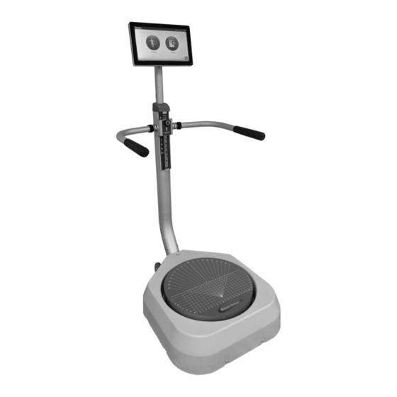
- Page 1 BALANCE SYSTEM™ SD (version 4.x) INSTRUCTIONS FOR USE 950-440 System, Balance SD, 115 VAC 15.6” display 950-441 System, Balance SD, 230 VAC 15.6” display 950-444 System, Balance SD, 100 VAC 15.6” display 950-450 Optional FreeSway Handles FN: 19-092-CLR Rev B 6/19...
- Page 2 BALANCE SYSTEM™ SD (version 4.x) This instructions for use document covers safe operation of the Balance System SD. Additional information and resources are available upon request or directly from the Biodex website: www.biodex.com/balance. Here, the user can find information from compliance to clinical support, and if the desired information is not found, Biodex can be contacted directly at supportservices@biodex.com.
-
Page 3: Table Of Contents
Table of Contents Definition of Symbols ........................ 5 Product Certifications and Classifications ................... 6 Warnings and Cautions ......................8 Important Safety Information ....................8 Introduction ......................... 10 Intended Use ....................... 10 Indications for Use ....................... 10 ... - Page 4 Motor Control Training ....................31 Maze Control Training ....................32 Random Control Training ..................... 33 Testing Modes ......................34 Sensory Integration Tests .................... 35 Clinical Test of Sensory Integration of Balance (CTSIB) ..........35 ...
-
Page 5: Definition Of Symbols
Definition of Symbols The following symbols and their associated definitions are used and implied throughout this manual. -
Page 6: Product Certifications And Classifications
Product Certifications and Classifications This product has received the following certifications and falls within the following classifications: • ETL Listed Electrical Equipment, Laboratory Use; Part 1, General Requirements for Safety conforms to UL 60601-1, CAN/CSA C22.2 No: 601-1-M90, EN 60601-1, EN 60601-1-4 and EN 60601-1-2 and CE Marked. - Page 7 Service (see Contact information). Note: Complete information on the Electromagnetic Compatibility for the Biodex Balance System can be located in the Compliance Supplement located on the Biodex website (www.biodex.com) or can be obtained by contacting Biodex Customer Service (see Contact information).
-
Page 8: Warnings And Cautions
WARNING: Never leave patient unattended. This medical electrical equipment requires special precautions for EMC and must be installed and used according to EMC information located on the Biodex website (www.biodex.com). WARNING: Only use approved power supplies. CAUTION: Operation for: 115–230 VAC, 50/60 Hz. - Page 9 CAUTION: The system is intended to remain in one location during operation. To relocate the system, the system is disconnected from power source. One person can move the system. Use the wheels to move the system. WARNING: Connecting electrical equipment to a multiple socket outlet (MSO) effectively leads to creating an ME SYSTEM, and can result in a reduced level of safety.
-
Page 10: Introduction
1. Introduction Intended Use The Balance System SD is an assessment tool which allows for testing and training in both static and dynamic formats. It is a versatile product, providing capabilities for balance assessment, concussion management, measurement of kinesthetic and proprioceptive abilities, and determining neuromuscular control (stability and degree of sway values). - Page 11 The optional VibroTactile™ System offers an additional form of sensory feedback. Using wireless technology, the belt responds with a vibrating sensation when the patient sways outside the target area. The vibrating feedback is helpful when training requires the patient’s eyes to be closed. Figure 1.2.
-
Page 12: Installation And Configuration
2. Installation and Configuration The Balance System SD is shipped in a single carton. The System is assembled before shipment and is ready to operate. The printer requires installation. Positioning the Balance System SD and Printer Stand 1. Determine the location for equipment. CAUTION: The plug is the method of disconnecting the system from the main power. -
Page 13: Installing The Printer
6. Refer to the printer manual for instructions for managing paper and ink cartridges. Important Notice Concerning Supplied Printer Ink Cartridges The printer ink cartridges for the Hewlett-Packard (HP) printer supplied with the Biodex product may not be compatible for customers outside of the North America, South America, Australia and some Pacific countries. -
Page 14: Turning On The System
6. Insert finishing washer over the stud. NOTE: The flange should be sticking up. 7. Apply Loctite to second nut. 8. Thread on the second nut and tighten. NOTE: Ensure the hooks are orientated correctly, pointing outwards as shown in the diagram before tightening. -
Page 15: Turning Off The System
Turning Off the System CAUTION: Shut down the software before unplugging the device. To preserve the Balance System SD database, use the proper sequence to turn off the system: 1. Shut down the software as illustrated in Figure 2.2. 2. Unplug the system from the power supply. Figure 2.2. -
Page 16: Configuring The System
Configuring the System 1. Touch <Utilities> on the Home screen. 2. At the Access ID Code screen, enter the ID code 159 and touch <OK>. 3. Touch <Configuration>. 4. Touch <System Configuration> 5. Select display options and set values for actions (see Figure 2.4). Figure 2.4. - Page 17 Function Default Options <Set Date/Time> Eastern 1. Touch to highlight the value Touch <Set Date/Time> to change the Standard being changed, and use the system time or date. Time (EST) < > or < > keys to increase or decrease the value. 2.
- Page 18 Table 2.2 Balance SD Configuration Functions Table. Function Default Options <Clinical Codes> Not applicable Not applicable <Sensory Integration mCTSIB default data Specify an alternative data Defaults> No BESS data set for mCTSIB or create BESS data-. Refer to Sensory Integration Tests.
-
Page 19: Common Icons And Buttons
Common Icons and Buttons Table 2.3. Action Table for Configuration Function Icons. Icon Name Action Home Returns to the Main Menu. Next Advances to the next screen. Back Returns to the previous screen. Confirms changes and advances to the next screen. Clear Tracing To erase the trace and start again, touch the <Clear Tracing>... -
Page 20: Planning A Session
3. Planning a Session For a productive patient session, practice the adjustments and display selections that will be needed, and review the patient history. Evaluating a Patient A postoperative patient must possess adequate muscular control to stabilize the joint. • Inadequate muscular control might lead to increased joint translation. - Page 21 Figure 3.3. Additional Information Screen. 5. If Training or Testing mode has already been selected, touch <Next> to continue to specify the session; otherwise, touch <OK>. For a Returning Patient: 1. From either the Patient Setup screen or the Add Patient screen, locate the correct patient. As illustrated in Figure 3.4, enter a name or ID number to search or scroll through the list of patients.
-
Page 22: Getting Started
4. Getting Started Starting a Session Explain the purpose and actions of the Balance System to patients before they step onto the • platform so that they are not surprised when the platform moves later in the session. Begin each session with the platform in the static position, even if conducting a dynamic •... -
Page 23: Freesway Handles
FreeSway Handles Figure 4.2. Adding the FreeSway Handles. The handles can now be interchanged between the FreeSway and regular support handles. Spin the black connectors to the left to remove handles. • Insert and spin black connectors to the right to attach the FreeSway Handles. •... -
Page 24: Adjusting The Display
The FreeSway handles have three challenge settings. Level A has the most movement excursion and provides the greatest challenge during • balance testing and training. Level B has less movement excursion than level A. • Level C has the least amount of mobility; it provides the least amount of challenge •... -
Page 25: Positioning The Patient's Feet
Positioning the Patient’s Feet 1. Have the patient stand in a natural stance on the static platform. The Position Patient screen displays the patient’s center of gravity as a dot (see Figure 4.5). 2. Adjust the patient’s foot placement until the dot is on or close to the center axis. 3. -
Page 26: Setting Up A Training Session
Setting Up a Training Session Patients should experience preliminary trials before a test session. Clinical research suggests completing three trials before a test. Touch <Training>, <training mode > and <Next>. • Touch <Test Options>. • The display displays the Test Options screen for the selected training mode. 1. -
Page 27: Saving Results And Creating Reports
9. After completing all trials, a “Test Complete” message is displayed. Touch <Results>. Saving Results and Creating Reports 1. To save the test data, touch <Save Results> and touch <OK>. The system displays “Save Results Completed.” If this test result is not saved, the system prompts to confirm. Touch <Print>... -
Page 28: Training Modes
5. Training Modes Percent Weight Bearing Weight Shift Postural Stability Motor Control Maze Control Random Control Custom Protocol CAUTION: Always supervise the patient. When patients are working with their eyes closed, be ready to assist in case they lose their balance. Percent Weight Bearing Training Percent Weight Bearing Training displays the percentage of weight-bearing force on a patient’s foot, ankle, knee, hip, and body side. -
Page 29: Weight Shift Training
Figure 5.1. Percent Weight Bearing Training. Weight Shift Training Weight Shift Training allows patients to practice shifting their weight in medial/lateral, anterior/posterior, or diagonal directions. This can be performed with the platform static or dynamic. The user sets the orientation and the target range. The patient attempts to keep the center of gravity indicated by the cursor within the target box (see Figure 5.2). -
Page 30: Postural Stability Training
1. Set the length of time for the training session. 2. Set the resistance level of the platform: Static or 1 through 12. Rotate Target Skill Level Show Tracing Clear Tracing 3. Touch <Rotate Target> repeatedly to show each orientation, and display the target for this training session. -
Page 31: Motor Control Training
3. Touch Place Target icon, and then touch a location on the screen. For different shapes of targets, touch <Targets>. Place up to nine targets. 1. Touch <Targets> repeatedly to select one of the three target areas. 2. To clear an unwanted target, touch Clear Target icon, and then touch the target. To clear more targets, touch <Clear Target>... -
Page 32: Maze Control Training
Maze Control Training In Maze Control Training mode, the patient follows a sequence of targets through a maze. The patient moves the curser to each target as it blinks but must not let the cursor touch a wall of the maze (see Figure 5.5). Scoring is a percentage of the net good hits divided by the total target hits. -
Page 33: Random Control Training
Random Control Training In Random Control Training mode, the patient responds to random movement of a target. The target is a red circle that starts in the center of the grid and moves in random directions. The clinician sets the size of the target and the speed of its movement. The patient moves the cursor to keep it within the target (see Figure 5.6). -
Page 34: Testing Modes
6. Testing Modes The Balance System SD runs and records the following tests (see Figure 6.1). Sensory Integration (mCTSIB, BESS) Postural Stability Bilateral Comparison. Postural stability performance of standing on one leg versus standing on the other Limits of Stability Motor Control Fall Risk Custom protocol. -
Page 35: Sensory Integration Tests
The test changes a sensory condition and measures how well the patient compensates. Table 6.1 lists the six CTSIB conditions. However, the Biodex Balance System SD uses the modified CTSIB (mCTSIB) test, which tests only conditions 1, 2, 4, and 5, as illustrated in Figure 6.2. - Page 36 Table 6.1. CTSIB Conditions. Surface Visual Input Eyes open Baseline condition: Input is visual, vestibular, and somatosensory. Eyes closed Evaluates vestibular and somatosensory inputs. Firm Conflict Some visual input but it conflicts with vestibular input. Condition relies on vestibular and somatosensory inputs.
-
Page 37: Balance Error Scoring System (Bess)
Balance Error Scoring System (BESS) The Balance System SD uses an enhanced BESS test. In a conventional BESS test, scoring is based on time and number of errors, which requires the evaluator’s judgment. With the Balance System SD, time and error counting is replaced with a measure of sway. Errors can be noted, but they do not affect the score. -
Page 38: Limits Of Stability (Los) Test
Limits of Stability (LOS) Test The LOS test challenges patients to control their center of gravity within the base of support. The LOS test measures how far from the center the patient can sway. The angle of sway is the number of degrees from the position of the patient’s center of gravity (0 degrees). -
Page 39: Postural Stability Test
Postural Stability Test The Postural Stability test assesses a patient’s ability to maintain a center of balance. It measures how much the patient’s position deviates from center and reports the average deviation as the stability index. Therefore, a low score is more desirable than a high score. Consider the following example: If a patient is in an off-center position on the platform, the stability index has a large value. -
Page 40: Motor Control Test
Motor Control Test The Motor Control test measures how patients control their center of gravity within a base of support. Like the Limits of Stability test, patients shift their weight to move the cursor from the center target to a blinking target and back as quickly and with as little deviation as possible. The same process is repeated for each of the targets. -
Page 41: Bilateral Comparison Test
Bilateral Comparison Test In a Bilateral Comparison test, the patient stands on one leg in the middle of the platform for a set time and at a set stability level. The patient performs the same test standing on the other leg. -
Page 42: Fall Risk Test
Fall Risk Test The Fall Risk test identifies potential fall candidates. The test measures the patient’s postural sway velocity to predict risk. Velocity is the speed of an individual's sway as balance is maintained. Test results are compared to age-dependent normative data. A high sway velocity when a patient is attempting to stand motionless suggests a deficit in postural control and assessment for lower extremity strength, proprioception, and vestibular or visual deficiencies. -
Page 43: Utilities
7. Utilities The Utilities screen displays the system’s firmware version and provides access to the Reports, Configuration, Patient Management, and System Maintenance screens, as illustrated in Figure 7.1. The platform can be locked at any time. Touch <Lock Platform> to make the platform level and firm. -
Page 44: Reports
Reports Use reports to analyze and present test results. If the patient has multiple tests, results can be compared as a progress report. The reports can be viewed or printed in PDF format. NOTE: From the Reports screen, codes or comments cannot be edited. Instead, select <Utilities>, <Patient Management>. - Page 45 Figure 7.3. Selecting a Test for a Report. The session can be viewed or printed. The <Repeat> button can be used to perform another session with the same settings as the highlighted session. The <New Training> and <New Test> buttons can be used to start a brand new session using the default settings. Three Report Types are available: Test Results, Progress Report –...
- Page 46 Printing a Report 1. Touch <Print Results> to display a preview (see Figure 7.5). Figure 7.5. Print Preview of Test Results. 2. Touch the <Magnifying Glass> icons to zoom in (+) or zoom out (-) to increase or decrease the size of the print preview. 3.
- Page 47 2. On the Test Results screen, select the test. Touch <Progress Report>. 3. Touch <View>. 4. On the Progress Report Selection screen, select a maximum of four conditions to include in the report (see Figure 7.7). Figure 7.7. Selecting Conditions for a Progress Report. 5.
-
Page 48: Configuration
Figure 7.9. Selecting a Data Set for a Progress Report. 7. The Progress Report displays a graph of the data. Touch <Print Report> to display options for printing. Configuration The Configuration screen includes two options: System Configuration and Balance System SD Configuration. - Page 49 Figure 7.10. Specifying Default Data for Sensory Integration Tests. Figure 7.11. Specifying Default Data Sets for Sensory Integration Tests. For each type of test, touch the Group and Age Range drop-down menus to make changes or add a new group (see Figure 7.11). Select the keypad icons beside each row to edit the normative data for that group.
-
Page 50: Changing Fall Risk Defaults
Changing Fall Risk Defaults Figure 7.12. Specifying Default Settings and Data for Fall Risk Tests. Use Fall Risk Defaults to change the default settings and associated normative data (see Error! Reference source not found. for the default settings). Note: Changing the default conditions will make comparisons to the default normative invalid. Note: Changing the default conditions will make comparisons to the default normative invalid. - Page 51 Figure 7.13. Custom Protocol List Screen. 7. Touch either <Training> or <Testing>. The procedure for creating the protocol is the same. 8. Configure the new protocol the way a standard Training or Testing session is set up. However, in this mode, there is no <Start> icon. Instead, touch <Test Options> to further specify the new protocol.
-
Page 52: Managing Custom Sensory Tests
Deleting a Custom Protocol 1. At the main screen, touch <Utilities>. 2. At the System Utilities screen, touch <Configuration>. 3. Select <Balance System SD Configuration> from the Configuration screen submenu. 4. Select <Custom Protocol List> from the Balance System SD Configuration submenu. 5. - Page 53 Figure 7.15. Specifying a Custom Sensory Integration Test. 9. Touch the Protocol Name field, and use the pop-up keypad to name the new protocol. 10. Touch the Condition Name fields, and use the pop-up keypads to add conditions. 11. Touch the <Foot Position> icon next to each condition to specify a regular stance, narrow base of support, single leg (left or right), or tandem straight.
-
Page 54: Patient Management
Figure 7.16. Sensory Integration Test Menu with Custom Test. Patient Management Select Patient Screen: Add Patient Used to create a profile for a new patient. Delete Used to delete records for a specific patient. Delete Range Used to delete a selected range of records for a specific patient. Edit Used to change the profile information for a specific patient. - Page 55 1. Touch <Utilities> on the Main screen. 2. Touch <Patient Management>. 3. At the Access ID Code screen, enter the ID code 159 or the site’s code, and touch <OK>. The Patient Management screen is displayed (see Figure 7.17). Figure 7.17. Patient Management Screen.
- Page 56 Exporting Patient Data Use Export Patient Data to copy a stored test to a file in the Biodex file format (.bio) or a CSV file format. A program such as Microsoft Excel can be used to open and edit the CSV file. For more information using CSV files, contact supportservices@biodex.com.
- Page 57 Set the Time Frame: From a specific date, Prior To a specific date, between two dates • (From/To). Enter the date. 3. Select the format to export: CSV or the Biodex proprietary format, biodata. 4. Touch <Export USB> to copy the filtered data to the folder named BioCsv or BioData. To Export a Multi-Record Data: Use the Time Frame option of All to export every patient test results for specific test type into a single CSV file.
- Page 58 Importing Patient Data Patient test files can be imported from the Biodex proprietary file format into a patient record. 1. Insert the flash drive with the file to import into one of the USB ports on the display. 2. On the Patient Management – Select a Patient screen, touch <Import>.
-
Page 59: Vibrotactile™ System
8. VibroTactile™ System Vibrotactile feedback or “cueing” incorporates a position-triggered, localized vibrating sensation on a belt worn by the patient. When patients close their eyes during a balance training session, the VibroTactile System provides biofeedback in the form of a “buzz” or vibration-cued signal. Vibrotactile cueing can be used as an indicator of positive reinforcement to affirm positional control. -
Page 60: Getting Started
Getting Started Vibrotactile feedback must first be enabled on the Balance System SD Configuration screen as illustrated below in Figure 1.2: Figure 8.2. Enable VibroTactile Feedback Option on the Balance System SD Configuration Screen. Attach the Link Box The link box provides a wireless link between the tactile belt on the patient’s waist and the biofeedback displayed on the screen. -
Page 61: Connect To The Display
Connect to the Display The link box will communicate with the display using the short USB to Micro USB cable. Once connected, a blue light will come on indicating the link box is powered. Figure 8.3. Installing the LinkBox to the Back of the Display. Connect the tactile belt receiver boxes to the belts. - Page 62 Figure 8.5. Align the Red Arrow on the Tactile Belt with the Patient’s Navel. Touch the <LINK> button to wirelessly connect with the link box. <RESET> can be used to re- establish communication with link box should the connection be lost. The link box is powered by the USB connection to the balance device’s display.
-
Page 63: Charging The Tactile Belt Receivers
Indicator Color Status LED on left Solid Blue Receiver Board is/was connected. Slow Blink Blue Building wireless network (searching). LED on right Solid Blue Active communications to application software. Dark No communications to application software. Table 8.2. LinkBox Indicator NOTE: When connecting a tactile belt receiver box, the connection status light can alternate from green to red, but the screen does not display a channel selection. - Page 64 Figure 8.8. Tactile Belt Receiver Boxes can be Charged with a Connection to a Wall Outlet or to the Display on the Device. The long USB to Micro USB cable is long enough to use on the Vibro Tactile System while a tactile belt receiver box is charging (e.g., the battery is dead).
- Page 65 Training Display Description The tactors corresponding with the on- screen targets will vibrate when the patient moves the cursor accordingly. Motor Control Tactors corresponding with patient movement on direction planes will vibrate when the boundary is exceeded (on- screen graphic will display a blue color) Percent Weight and turn off when the patient stays within Bearing...
- Page 66 When vibrotactile feedback is being employed during a training session, it will be denoted at the top of the training report page:...
-
Page 67: Configuring Equipment In Facilities With One Vibrotactile System
Configuring Equipment in Facilities with One VibroTactile System Each VibroTactile System comes with one link box and two tactile belt receiver boxes. The link box will be labeled with a sticker denoting A0, and the two tactile belt receiver boxes will be labeled A1 and A2. - Page 68 If a tactor is not vibrating during this test, something is not working correctly. Try performing the configuration steps again. If there is still a problem, contact Biodex customer service. Note: Even if the link box and tactile belt receiver boxes do not need to be configured, a tactor test can be performed by touching the wireless/battery symbol on the main testing/training screen (Fig 1.10).
-
Page 69: Configuring Equipment In Facilities With Multiple Vibrotactile Systems
If more than one VibroTactile System is purchased, some steps are required to ensure that the various link boxes and tactile belt boxes do not interfere with each other. Please contact Biodex Customer Support for assistance. Patients with Pacemakers At the time of writing, there is no information regarding use of the VibroTactile System with patients having pacemakers. -
Page 70: Maintenance
9. Maintenance The Balance System SD requires only basic maintenance, performed as needed. System Maintenance Use the System Maintenance main menu get access to the following actions: Backup to USB Restore from USB Database Cleanup Backing Up Data to USB The Backup operation makes a backup of the entire system, not only the database. -
Page 71: Updating System Software
Database Cleanup compresses the system’s file size. Perform this operation according to the site’s policy. Updating System Software 1. Download the latest software from www.biodex.com to a flash drive, in the root directory of the drive. 2. Go to the Home screen. -
Page 72: Maintaining The Printer
For questions or assistance, contact the Biodex Customer Service Department. Maintaining the Printer Follow the instructions in the printer manual. If replacement ink cartridges cannot be found, contact either Biodex Support or a Biodex distributor. Disposal An appropriate waste disposal company is to be contacted (i.e., the local collection point for waste separation). -
Page 73: Specifications And Certifications
10. Specifications and Certifications Dimensions: Base: 26" w x 37" depth x 8.5" h (66 x 94 x 21.5 cm) Platform: 21.5" diameter (55 cm) Product Weight: 235 lb (106.5 kg) All-In-One Flat Panel Display: 15.6" Color Touchscreen, Windows Operating System, Ethernet, USB, Video/Audio Out, Built-In Speakers and Color Printer.
Need help?
Do you have a question about the Balance System SD Series and is the answer not in the manual?
Questions and answers