Table of Contents
Advertisement
Quick Links
Advertisement
Table of Contents

Related Manuals for W&H Lara RIL-117


Summary of Contents for W&H Lara RIL-117
- Page 1 Instructions for use RIL-117 RIL-122 RIL-1 - ENG - Rev04...
-
Page 3: Table Of Contents
Table of contents Conformity Printer selection (optional) Symbols and messages Label printer selection (optional) Introduction Label printer usage (optional) About this manual Label content description Use restrictions Sterilizer tests Safety information Sterilizer performance tests Safety warnings Bowie and Dick test Responsibility Helix test Getting started... - Page 4 4000 cycle or five-year maintenance Extraordinary maintenance Battery-operated door opening tool Disposal Diagnostic Errors Troubleshooting Technical data Sterilization cycles Sterilization cycle phases Technical data Recommendations for validation Diagrams Water quality Accessories, spare parts, consumables Authorized W&H service partners Documentation forms W&H installation check-list Helix test documentation form LARA ...
-
Page 5: Conformity
Note: Every new sterilizer is delivered with a Declaration of Conformity and a Conformity Warranty Card. CONFORMITY TO EUROPEAN STANDARDS AND DIRECTIVES STERILIZER featuring sterilization cycles conform with the following standards: Standards Description Directives Medical Device Directive (MDD). Medical Device Directive 93/42/EEC for devices class IIb, in accordance with the Rule 15 –... -
Page 6: Symbols And Messages
Symbols and messages SAFETY SYMBOLS USED IN THIS MANUAL WARNING: Indicates a hazardous situation that, if not avoided, could CAUTION: Indicates a hazardous situation that, if not avoided, could result in death or serious injury. result in minor or moderate injury. Related to a sterilizer, these warnings indicate hazardous situations that could result in non-sterile conditions (e.g. -
Page 7: Introduction
Introduction CONTENTS OBLIGATIONS WITH REGARD TO THIS MANUAL This section deals with the following subjects: This manual is an integral part of the product and accompanies it for its entire working life. It must be consulted in all situations related About this manual to the life cycle of the product, from its delivery through to Use restrictions... -
Page 8: Use Restrictions
Introduction COPYRIGHT NOTICE PROVIDED FEATURES Copyright © 2019, W&H Sterilization Srl See "Sterilization cycles" on page 111 for the full list of key program features, including sterilization time, temperature and All rights reserved in all countries. recommended load type. All drawings, images and texts contained in this manual are the property of the manufacturer. -
Page 9: Safety Information
Safety information CONTENTS ELECTRICAL RISKS This section deals with the following subjects: Do not pour water or any other liquids over the sterilizer (risk of electrical short circuits). Safety warnings Switch off the sterilizer and unplug the mains Responsibility cable before inspecting, carrying out maintenance or servicing the sterilizer. -
Page 10: Responsibility
Safety information TAMPERING MANUFACTURER RESPONSIBILITY The manufacturer can only accept responsibility for the safety, Do not remove the name plate or labels from the reliability and performance of the product when the product sterilizer. itself is installed, used and serviced in accordance with the Repairs, maintenance or service must be carried Instructions for use. -
Page 11: Getting Started
Getting started CONTENTS Unpacking This section deals with the following subjects: Unpacking UNPACK THE STERILIZER Handling CAUTION! Heavy product. The sterilizer must be removed Product description from the box and transported by two authorized technicians. The sterilizer must be removed from the box and Installing the sterilizer transported using the specific straps. - Page 12 Getting started WARNINGS Notice: Check the external condition of the box and the sterilizer. In case of any damage, immediately contact the dealer or shipping agent that has carried out the transport. Keep the packaging for shipping or transporting the sterilizer in the future. Note: The packaging of the product is environmentally friendly and can be disposed of by industrial recycling companies.
-
Page 13: Handling
Getting started Handling HOW TO RELOCATE THE STERILIZER Before transport: Completely drain both water tanks (see "Draining the used and clean water tank" on page 92). Allow the sterilization chamber to cool down. Use original packaging when shipping or transporting the sterilizer. -
Page 14: Product Description
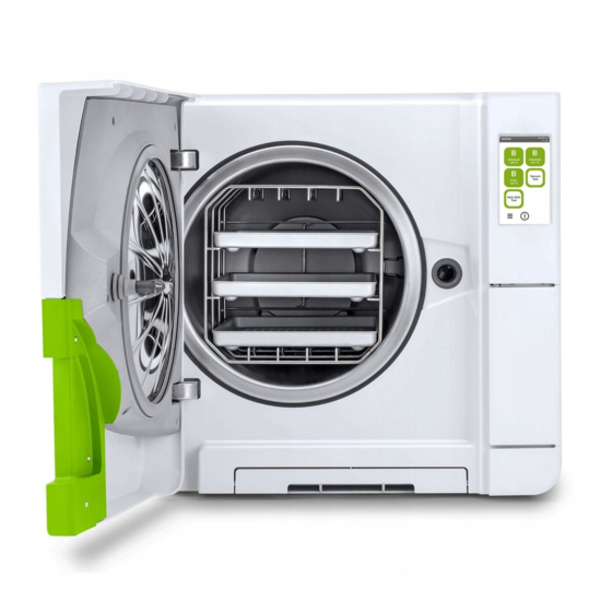
Getting started Product description FRONT VIEW Part Description Chamber door Tank filling cover-cap Water tank cover Touch screen Service door Sterilization chamber Dust filter Reset button of the thermostat switch Door seal Door pin LARA | Instructions for use | RIL-1 ENG Rev04 | 28/02/2019 | © 2019 W&H Sterilization Srl... - Page 15 Getting started UPPER INTERNAL STRUCTURE Part Description Tank Water level sensor Water tank cover Internal tank cover Tank internal filters with metal cartridges LARA | Instructions for use | RIL-1 ENG Rev04 | 28/02/2019 | © 2019 W&H Sterilization Srl...
- Page 16 Getting started COMPONENTS BEHIND THE SERVICE DOOR Part Description Bacteriological filter Mains switch Identification label Used water drain port (grey) Clean water drain port (blue) Drain tube release button USB port LARA | Instructions for use | RIL-1 ENG Rev04 | 28/02/2019 | © 2019 W&H Sterilization Srl...
- Page 17 Getting started REAR VIEW Part Description USB port (optional) Air gap cover Test connection Pressure safety valve cover Used water drain Water supply inlet Condenser grid Mains cable guide Mains cable plug socket LARA | Instructions for use | RIL-1 ENG Rev04 | 28/02/2019 | © 2019 W&H Sterilization Srl...
- Page 18 Getting started CHAMBER ACCESSORIES Part Description Tray Chamber rack. In the normal position, it can host 5 trays horizontally or 3 cassettes/containers vertically. In a 90° degrees rotated position, it can host 3 trays or 3 cassettes/containers horizontally. LARA | Instructions for use | RIL-1 ENG Rev04 | 28/02/2019 | © 2019 W&H Sterilization Srl...
-
Page 19: Installing The Sterilizer
Getting started Clearance requirements to ensure proper air circulation: Installing the sterilizer LOCATION REQUIREMENTS Notice: Do not place the sterilizer so that it is difficult to operate the controls behind the service door. Do not place the sterilizer so that it is difficult to disconnect the power supply plug. - Page 20 Getting started The electrical power supply of the sterilizer must fulfill all applicable INSTALLING THE STERILIZER standards in the country of use, and must comply with the data WARNING! In case of sterilizer malfunctions immediately label on the back of the sterilizer. unplug the sterilizer and call for service.
-
Page 21: Operating With The Sterilizer
Getting started After a quick autotest the Operating with the sterilizer sterilizer automatically turns in standby mode. See "Standby POWER ON/OFF THE STERILIZER mode" on page 33. Press the power switch behind the service door: the visual indicator on the power switch will turn green. - Page 22 Getting started HOMEPAGE DESCRIPTION Part Description Title/purpose of the screen, or the cycle number and the current date and time Available cycles Note: The S Fast 134 cycle is optional, activated with Fast Cycle activation code, see "S Fast 134 cycle activation"...
-
Page 23: User Interface Menu
Getting started User interface menu = optional with Activation code STRUCTURE AND NAVIGATION = optional LARA | Instructions for use | RIL-1 ENG Rev04 | 28/02/2019 | © 2019 W&H Sterilization Srl... - Page 24 Getting started MAIN MENU FUNCTIONS Icon Function Label Icon Function Label Language Sets the language. Menu Opens the menu. Date & Time Sets time and date values and format. Settings Sets the device. Sterilizer Sets the sterilizer name. Name Opens the pages to monitor the performed cycle data and Traceability manage users and printing.
- Page 25 Getting started Icon Function Icon Function Label Label Remote data Only with a network connection set. Opens the page to Delete User Administrator only. Deletes a user. storage manage the remote storage. Settings Only with a network connection set. Sets the parameters Reset user PIN Administrator only.
- Page 26 Getting started Icon Function Icon Function Label Label Formats the USB pen drive. Format Dust Filter Shows the status of the dust filter for replacement and resets its counter to zero. Optional, activated with an activation code. Selects the Label Door Shows the status of the door gasket for replacement and label printer and sets the printout layout.
- Page 27 Getting started COMMON COMMANDS AND ICONS Icon Function Icon Function Icon Function Opens a screen with other Indicates that an error occurs. settings/options. Enters/exits the standby mode. Refreshes the page. Indicates that the option checked is working properly. Indicates the value that may be Plays a video.
- Page 28 Getting started Icon Function Indicates that the option is active/not active. Indicates that the option is enabled/disabled. Indicates that the user is using the administrator credentials. Confirms the active option and saves a setting or a parameter. Copy the system info to the USB pen drive.
-
Page 29: Sterilizer Setup
Getting started Sterilizer setup SET THE DATE AND TIME To change the current date and time: SET THE LANGUAGE On the homepage tap > > > On the homepage tap > > > Tap the value you want to change (time, date, format): the highlighted Tap the language you prefer. - Page 30 Getting started SET THE STERILIZER NAME SET THE DISPLAY BRIGHTNESS To change the sterilizer name that appears in the cycle reports: To change the display brightness: On the homepage tap > > On the homepage tap > > > > Tap the text box: ...
-
Page 31: User Authentication (Optional)
Getting started SET THE NETWORK ADDRESS (OPTIONAL) User authentication (optional) Refer to your network administrator or IT manager for more information about your network. FUNCTION AVAILABILITY If your network supports dynamic IP, skip this procedure. Otherwise To access the user management functions the Traceability follow this procedure and enter the data suggested by your network activation code must be entered. -
Page 32: Usb Pen Drive
Getting started On the homepage tap > > WHAT TO DO IF YOU FORGET YOUR PIN If you are... Then contact... Tap your user name. a common user the administrator Enter your current PIN and tap the administrator your authorized service provider to confirm. -
Page 33: Standby Mode
Getting started FORMAT THE USB PEN DRIVE Standby mode On the homepage tap > > DESCRIPTION When in standby mode, the sterilizer display remains dark and the Insert the USB pen drive in one of sterilizer chamber is not heated to save energy. If the sterilizer is the two USB ports. - Page 34 Getting started EXIT THE STANDBY MODE CHANGING STANDBY MODE DELAY TIME or open or close the chamber On the homepage tap > > door. > to change the delay. to confirm and go back to the previous page. LARA | Instructions for use | RIL-1 ENG Rev04 | 28/02/2019 | © 2019 W&H Sterilization Srl...
-
Page 35: Administrator
Administrator CONTENTS ADD A USER This section deals with the following subjects: On the homepage tap > > User management (optional) Traceability options (optional) Tap your user name. Enter the PIN and tap to confirm. User management (optional) FUNCTION AVAILABILITY To access the user management functions the Traceability activation code must be entered. - Page 36 Administrator Tap the text box: a keyboard If desired, tap to give the appears. administrator authority to the new user. to confirm: the PIN of the new user is set to "0000" and a confirmation message appears. and then to go back to the previous page.
- Page 37 Administrator RESET A USER PIN On the homepage tap > > Tap your user name. Enter the PIN and tap to confirm. Tap the user name you want to delete. to confirm. and the user name for which you want to reset the PIN. to confirm: ...
-
Page 38: Traceability Options (Optional)
Administrator Traceability options (optional) SET THE TRACEABILITY OPTIONS On the homepage tap > > FUNCTION AVAILABILITY To access the user management functions the Traceability Tap your user name. activation code must be entered. The activation code is required Enter your PIN and tap only at the first access to the User Management ( ) or the Options confirm. -
Page 39: Managing Printers
Managing printers On the homepage tap > > CONTENTS This section deals with the following subjects: Tap the model of the printer to use. Printer selection (optional) to confirm and go back to Label printer selection (optional) the previous page. Label printer usage (optional) Label content description Printer selection (optional) - Page 40 Managing printers connected to the sterilizer, while the shared label printer is SELECT A SHARED LABEL PRINTER connected to another sterilizer in the network. Note: Function available only if the LAN/Wi-Fi connection has been activated (optional). SELECT AND CALIBRATE A LOCAL LABEL PRINTER Ensure the sterilizer to which the printer is physically connected is On the homepage tap...
-
Page 41: Label Printer Usage (Optional)
Managing printers From the sterilizer from which the From the sterilizer to which the printer is not physically connected, printer is connected, confirm the tap homepage > > > printer sharing. to print a test label again. Tap the text box and enter the IP address previously noted. - Page 42 Managing printers AUTOMATIC PRINTING OPTION SET THE MANUAL LABEL PRINTING The automatic printing option permits to automatically print a The manual printing option permits the user at the beginning of a preset number of labels after a successful sterilization cycle. The sterilization cycle to set manually the number of labels to print.
- Page 43 Managing printers DISABLE THE LABEL PRINTING If the label printing is disabled, no label can be printed at the end of a sterilization cycle. On the homepage tap > > Activate Disabled. to confirm and go back to the previous page. LARA ...
-
Page 44: Label Content Description
Managing printers Label content description STRUCTURE Part Description Sterilizer model Serial number Software release Traceability code (alphanumerical and bar code) Released Depending on the traceability settings, this field may contain one of the following elements: the user who released the cycle the user who started the cycle the sterilizer ID Cycle... -
Page 45: Sterilizer Tests
Sterilizer tests CONTENTS This section deals with the following subjects: Sterilizer performance tests Bowie and Dick test Helix test Vacuum test Sterilizer performance tests TESTS THAT CAN BE PERFORMED ON THE STERILIZER Test Purpose Reference Bowie and Dick test Validate the sterilizer performance for textile load sterilization. See "Bowie and Dick test"... - Page 46 Sterilizer tests PURPOSE OF THE TEST The test is used to validate the sterilizer performance for textile load sterilization. DESCRIPTION It consists of several sheets of paper wrapped in a small packet with a chemical heat-sensitive indicator sheet in the middle. The colour assumed by this indicator sheet at the end of the sterilization cycle gives the result of the test.
- Page 47 Sterilizer tests On the homepage tap Helix-B&D test. and enter your credentials if required: the chamber door locks. Wait until the end of the test and tap OPEN: the chamber door unlocks. Enter your credentials if required. Open the chamber door, extract the tray using the tray holder and take the test pack.
- Page 48 Sterilizer tests INTERPRET THE TEST RESULT Test Indicator What happened What to do next passed The entire surface of the indicator sheet has changed colour. Certain ares of the indicator sheet have not changed colour since there was an air Repeat the test.
-
Page 49: Helix Test
Sterilizer tests Helix test CAUTION! Follow local/national guidelines on the frequency of testing. PURPOSE OF THE TEST The test is used to validate the sterilizer performance for hollow items. DESCRIPTION It consists of a 1.5 m long tube open on one side and closed with a capsule containing a chemical indicator strip on the other side. The colour assumed by this indicator strip at the end of the sterilization cycle gives the result of the test. - Page 50 Sterilizer tests Place the tube with the capsule in the center of a tray in the lowest rack position and close the chamber door. On the homepage tap Helix-B&D test. To set the duration of the Plateau/Sterilization phase and other settings, tap and enter your credentials if required: the chamber door locks.
- Page 51 Sterilizer tests Open the chamber door, extract the tray using the tray holder and take the tube. CAUTION! Risk of burns. The test pack is very hot at the end of the cycle. Wear appropriate PPE (e.g. gloves). Unscrew the tube capsule and remove the indicator strip. Check the change in colour.
-
Page 52: Vacuum Test
Sterilizer tests Vacuum test CAUTION! Follow local/national guidelines on the frequency of testing. Notice: If a drainage period of the S Fast 134 cycle is still operating, wait the drainage to be finished and the sterilizer to be both cold and dry. Otherwise, a false negative outcome could occur. - Page 53 Sterilizer tests On the homepage tap Vacuum test. and enter your credentials if required: the chamber door locks. Wait until the end of the test and tap OPEN: the chamber door unlocks. Enter your credentials if required: a message informs if the test passed or failed. If the test failed, see "What to do when the test failed"...
-
Page 54: Sterilization Cycles
Sterilization cycles CONTENTS DENTAL HANDPIECES EXTERNAL DISINFECTION This section deals with the following subjects: This procedure reduces the risk of infection during cleaning and maintenance of the dental handpieces. Load maintenance and preparation Wear protective gloves during disinfection. Prepare the sterilizer Avoid using abrasive disinfectants (pH-value 2.5 –... - Page 55 Sterilization cycles DENTAL HANDPIECES EXTERNAL CLEANING CORRECT LOAD PLACEMENT This procedure involves the removal of residues (blood, dentine, WARNING! Do not overload trays and the chamber. Adhere to etc.) that adhere to critical areas such as spray outlets, light ports, the maximum load weight limits (see "Sterilization cycles"...
-
Page 56: Prepare The Sterilizer
Sterilization cycles PARTIAL LOAD Load type Placement If the chamber is just partially loaded, place the load in such a way On trays allowing adequate space in-between Pouched items that the space in-between the trays is maximized. Spread items bags. Ensure that packs do not touch the walls of evenly on multiple trays. -
Page 57: Sterilization Cycle Description
Sterilization cycles To enjoy the full benefit of short cycle times, always place the FILLING THE CLEAN WATER TANK load on the uppertray of the chamber rack and remove other Switch the sterilizer ON and remove the tank filling cover-cap. trays from the chamber. -
Page 58: Sterilization Cycle Management
Sterilization cycles To activate the ECO DRY plus mode is required the Performance RUN A STERILIZATION CYCLE IMMEDIATELY activation code. To require the activation code please refer to the Activation code instructions. On the homepage tap the desired cycle. To activate the function proceed as follows: Note: The ECO ... - Page 59 Sterilization cycles Check the cycle requirements. Wait the end of the sterilization. Tap to view the cycle parameters in Check the icon in the top left corner real time. See "View the cycle of the page to know the drying parameters"...
- Page 60 Sterilization cycles Tap the number you want to change SET THE STERILIZATION CYCLE START and tap to increase it or You may schedule the start of the sterilization cycles at a certain decrease it. date and time (e.g., if you want to load the sterilizer in the evening and run standard sterilization cycle early the next morning before to confirm and go back to office hours).
- Page 61 Sterilization cycles SET THE DRYING TIME to increase the The drying time of the AUTO DRY and ECO DRY plus modes is minutes or decrease them. Note: for the minimum value of the automatically adjusted to the total amount of load and cannot be drying time for each cycle see modified (see "Available automatic drying modes"...
- Page 62 Sterilization cycles VIEW THE CYCLE PARAMETERS STERILIZATION CYCLE PAGE You can check the real time cycle parameters or the cycle Following are the information displayed while a cycle is running: parameters at the end of the cycle. Following is an example: Part Description While the sterilization cycle is...
- Page 63 Sterilization cycles END OF A STERILIZATION CYCLE STOP A STERILIZATION CYCLE When a cycle is successfully finished, the "Cycle completed" WARNING! You can stop the cycle at any time. Instruments message appears on the screen. To end the cycle: must not be considered sterile if this occurs before the DRY phase.
- Page 64 Sterilization cycles to abort the stop command. Check the message. See The cycle continues programmed. "Messages of a stopped sterilization cycle" on the next to abort the cycle: the page. sterilizer starts a reset phase. to view the cycle Notice: Do not switch off the sterilizer parameters.
-
Page 65: Unloading
Sterilization cycles MESSAGES OF A STOPPED STERILIZATION CYCLE WHAT HAPPENS WITH UNSAVED CYCLES Following are the messages: If for any reason (e.g. USB memory full, USB pen drive disconnected, etc.) some cycles cannot be saved, no alert is shown. If still stored Load not sterile: Do not use items on patients! in memory, the unsaved cycles will be copied in a working USB pen Drying interrupted: The load might be wet. - Page 66 Sterilization cycles to print the report, or tap PRINT OR SAVE A CYCLE REPORT ON THE USB PEN DRIVE to save the report on the USB pen On the homepage tap > > drive. Scroll the list and tap the desired sterilization cycle: the report opens.
- Page 67 Sterilization cycles to increase or decrease the number of label to be printed. to save the set number for the next time. to print the labels required. SAVE ALL THE CYCLE REPORTS ON THE USB PEN DRIVE to print traceability labels The number of reports that can be saved on the USB pen drive for the selected cycle.
- Page 68 Sterilization cycles SET THE REMOTE FOLDER FOR SAVING THE REPORTS (OPTIONAL) Not mandatory. Enter the domain To activate the remote storage and set the necessary parameters name. do the following: to require the authentication credentials to On the homepage tap >...
- Page 69 Sterilization cycles TEST THE DATA STORAGE (OPTIONAL) SAVE ALL THE CYCLE REPORTS IN A REMOTE FOLDER (OPTIONAL) Note: The test function is available only if the remote data storage is Note: The save all function is available only if the remote data storage is enabled.
- Page 70 Sterilization cycles CYCLE REPORT STRUCTURE Data Description Following the structure of a cycle report: Sterilizer model Sterilizer serial number Software rev. Software revision number Sterilizer Name Surgery – practice – doctor name Cycle Name of the executed cycle Number Cycle counter Sterilizat.
- Page 71 Sterilization cycles Data Description Cycle time Cycle time Date(below) Cycle end date and time "Cycle completed" Cycle outcome Trk. Tracking code for traceability management LARA | Instructions for use | RIL-1 ENG Rev04 | 28/02/2019 | © 2019 W&H Sterilization Srl...
-
Page 72: Maintenance
Maintenance CONTENTS Warnings for maintenance operations This section deals with the following subjects: WARNINGS Warnings for maintenance operations Ordinary maintenance WARNING! Turn the sterilizer OFF and remove the power cord before beginning any maintenance. Follow all health, Monthly or 50-cycle maintenance safety, cross-infection and cross-contamination protocols. -
Page 73: Ordinary Maintenance
Maintenance Note : Even if the maximum cycle number is not reached, it is Ordinary maintenance recommended to replace the consumable parts every year, or if they appear worn or damaged, or if the filters are clogged or discolored. MAINTENANCE BY THE USER EXPIRED MAINTENANCE Frequency Cycles... - Page 74 Maintenance REPLACE THE CONSUMABLE BEFORE THE MAINTENANCE DUE to see an animated DATE replacement procedure. If you replace the consumables before the request of replacement When you have replaced the appears, you should manually reset the counters through the consumable tap to confirm: the following procedure.
-
Page 75: Monthly Or 50-Cycle Maintenance
Maintenance Monthly or 50-cycle maintenance CLEANING THE DOOR SEAL AND THE CHAMBER FACE SIDE Proceed as follows: Clean the seal seat and the chamber face side with a damp, lint-free cloth moistened with clean water. Notice: Do not use abrasive products, cutting tools or sharp objects. If you use a detergent solution, be careful not to get in contact with the plastic body of the front cover. - Page 76 Maintenance CLEANING THE CHAMBER AND THE CHAMBER ACCESSORIES Proceed as follows: Remove the trays and the chamber rack. Clean the chamber with a damp sponge and a mild detergent solution paying attention not to bend or damage the temperature probe inside the sterilizer chamber.
- Page 77 Maintenance CLEANING THE CHAMBER FILTER Proceed as follows: Allow the sterilization chamber to cool down. Empty the sterilizer chamber by removing the trays and the rack. Turn the filter cap at the back of the chamber (bottom/center) counter-clockwise. LARA | Instructions for use | RIL-1 ENG Rev04 | 28/02/2019 | © 2019 W&H Sterilization Srl...
- Page 78 Maintenance Remove the filter cap and the cartridge filter. Rinse the cartridge filter with tap water. Insert the cartridge filter in the filter cap. Insert the filter cap with the cartridge filter in its original position. LARA | Instructions for use | RIL-1 ENG Rev04 | 28/02/2019 | © 2019 W&H Sterilization Srl...
- Page 79 Maintenance Lock the filter cap by turning it clockwise. CLEANING THE EXTERNAL SURFACES OF THE STERILIZER Proceed as follows: Clean all external sterilizer covers with a slightly damp cloth moistened with water. Notice: Never use disinfectants, detergents or abrasive products. LARA ...
-
Page 80: 400-Cycle Maintenance
Maintenance 400-cycle maintenance REPLACING THE BACTERIOLOGICAL FILTER Notice: If you replace this consumable before the maintenance due date you have to reset the cycle counter. See "Replace the consumable before the maintenance due date" on page 74. Proceed as follows: Open the service door. - Page 81 Maintenance REPLACING THE DUST FILTER Notice: If you replace this consumable before the maintenance due date you have to reset the cycle counter. See "Replace the consumable before the maintenance due date" on page 74. Proceed as follows: Open the chamber door. Pull out the dust filter handle from underneath the sterilizer.
- Page 82 Maintenance Insert the new filter into the handle. Slide the handle back into its original position. Close the chamber door. LARA | Instructions for use | RIL-1 ENG Rev04 | 28/02/2019 | © 2019 W&H Sterilization Srl...
-
Page 83: 800-Cycle Or Biannual Maintenance
Maintenance 800-cycle or biannual maintenance SEQUENCE OF PROCEDURES TO CLEAN THE WATER TANKS To clean the water tanks, proceed as follows: 1. "Prepare the sterilizer for cleaning the water tanks" below. 2. "Access to the water tanks" on the next page. 3. - Page 84 Maintenance ACCESS TO THE WATER TANKS Proceed as follows: Lift the water tank cover. LARA | Instructions for use | RIL-1 ENG Rev04 | 28/02/2019 | © 2019 W&H Sterilization Srl...
- Page 85 Maintenance Remove the internal tank cover. Clean and dry the internal tank cover and its rubber membrane to eliminate any condensate. Notice: Never use disinfectants, strong detergents or abrasive products. Use a slightly damp cloth moistened with water. LARA | Instructions for use | RIL-1 ENG Rev04 | 28/02/2019 | © 2019 W&H Sterilization Srl...
- Page 86 Maintenance CLEAN THE WATER TANKS Notice: Do not touch the water level sensors. If misplaced or misaligned from their original position, the operation of the sterilizer could be impaired. Proceed as follows: Clean the internal tank surfaces with a soft sponge and a mild detergent solution. Notice: Never use disinfectants, strong detergents or abrasive products.
- Page 87 Maintenance Remove the internal filters. Clean the metal cartridges of the internal filters with tap water. Reposition the internal filters. LARA | Instructions for use | RIL-1 ENG Rev04 | 28/02/2019 | © 2019 W&H Sterilization Srl...
- Page 88 Maintenance Reposition the internal tank cover and then the water tank cover. Detach the drain tube. LARA | Instructions for use | RIL-1 ENG Rev04 | 28/02/2019 | © 2019 W&H Sterilization Srl...
-
Page 89: 800-Cycle Maintenance
Maintenance 800-cycle maintenance REPLACING THE DOOR SEAL Notice: If you replace this consumable before the maintenance due date you have to reset the cycle counter. See "Replace the consumable before the maintenance due date" on page 74. Proceed as follows: Fully open the chamber door. - Page 90 Maintenance Insert the new seal and press first up and down. Press left and right and then the entire seal circumference to ensure its perfect placement. Notice: A steam discharge can damage the sterilizer plastic parts. Ensure the seal does not stick out. Wipe any residual water and run a Vacuum and Helix test to check for perfect tightness of the seal.
-
Page 91: 4000 Cycle Or Five-Year Maintenance
Maintenance 4000 cycle or five-year maintenance Element Replace Clean Check Internal parts, with particular care for the condenser fins and the main board GENERAL CHECK AND SERVICE REQUIRED Notice: Regular service is imperative to ensure continuous and Pneumatic connections effective operation of the sterilizer. Electrical connections A general check and service should be carried out every 4000 Temperature and pressure calibration... -
Page 92: Extraordinary Maintenance
Maintenance Extraordinary maintenance DRAINING THE USED AND CLEAN WATER TANK If you left accidentally the tanks full for more than seven days or if you plan not to use the sterilizer for at least seven days, you have to drain the tanks. - Page 93 Maintenance RESET THE SAFETY THERMOSTAT The sterilizer is fitted with a safety thermostat to prevent it from overheating. If the safety thermostat operates because of too high temperatures, the error 240 or a timeout error is displayed. The thermostat must be reset manually. Proceed as follows: Switch the sterilizer OFF and remove the mains cable.
- Page 94 Maintenance Open the chamber door. Remove the dust filter and move the sterilizer closer to the shelf edge. Push the reset button of the thermostat switch: a click sound indicates that the thermostat switch has been reset. LARA | Instructions for use | RIL-1 ENG Rev04 | 28/02/2019 | © 2019 W&H Sterilization Srl...
- Page 95 Maintenance Insert the dust filter back into its original position. Close the chamber door. Connect the mains cable and place the sterilizer back into its original position. Switch the sterilizer ON. Wait for the sterilizer to finish the error reset phase and follow the instructions on the display.
-
Page 96: Battery-Operated Door Opening Tool
Maintenance Battery-operated door opening tool WARNING ABOUT OPENING THE DOOR IN EMERGENCY WARNING! High pressure. Risk of explosion, jet of hot steam, sudden opening of the door. Execute the following procedure only if necessary and only when NO RESIDUAL PRESSURE IS IN THE CHAMBER. Any attempt to open the door while the unit is still hot or under pressure could expose the operator and the surrounding personnel to serious risk. - Page 97 Maintenance Take the auxiliary cable loom included in the sterilizer box. Firmly open the service door. Unscrew the bacteriological filter by hand (counter-clockwise). LARA | Instructions for use | RIL-1 ENG Rev04 | 28/02/2019 | © 2019 W&H Sterilization Srl...
- Page 98 Maintenance Plug two batteries into the connectors. Holding the service door pulled, plug the plastic connector into the socket behind the bacteriological filter. As soon as the door opens, unplug the plastic connector to prevent system overload and consequent damage. LARA ...
-
Page 99: Disposal
Maintenance Disposal DISPOSAL RESPONSIBILITY Separate the various components according to the materials they are made of. Drop the sterilizer with a company that specializes on the recycling of related products. Do not abandon the sterilizer in unsecured places. Always refer to current/applicable laws and rules in the country of use. The same instructions apply to disposal of all used consumable parts. -
Page 100: Diagnostic
Diagnostic CONTENTS This section deals with the following subjects: Errors Troubleshooting Errors CHECKS AND ACTIONS Notice: For any error not listed in this table, call technical service. LARA | Instructions for use | RIL-1 ENG Rev04 | 28/02/2019 | © 2019 W&H Sterilization Srl... - Page 101 Diagnostic Code Description and actions Actions Load cannot be considered sterile. See "End of a Repeat the cycle. sterilization cycle" on page 63 If the problem persists, call service. Check if the mains switch or network circuit breaker is OFF. Check if the mains cable is properly connected.
- Page 102 Diagnostic Code Description and actions Actions 13x to 16x Check water level in the clean water tank. Reset the thermal Repeat the cycle. overload. If the problem persists, call service. Switch the sterilizer OFF and ON. Clean the door seal and the chamber face side. Check if the load placed in the sterilization chamber complies with the MAXIMUM WEIGHT LIMITS.
- Page 103 Diagnostic Code Description and actions Actions Check the door seal. Clean or replace it if necessary. Repeat the cycle. If the problem persists, call service. Clean the chamber face side. Clean the chamber filter. Check if chamber filter is properly locked in the cap. Check the load does not exceed the MAXIMUM WEIGHT LIMITS.
- Page 104 Diagnostic Message/Alert Description Action Please close the door. The door must be locked, but you didn't close it. Close the door so it can be locked. Non-conform water The clean water quality is bad (conductivity You may run a cycle but the water must be replaced soon, otherwise the unit will between 15 and 50 μS/cm).
- Page 105 Diagnostic Message/Alert Description Action Remote data storage Some cycle reports couldn't be saved in the No action possible. The cycles were overwritten in the sterilizer database before being network because the sterilizer memory is limited saved, and there is no way to recover them. File lost.
-
Page 106: Troubleshooting
Diagnostic When the OPEN button appears, tap Troubleshooting it to unlock the door. Confirm the opening of the door. MANAGING ERRORS If during a sterilization cycle an error occurs do the following: Notice: Water could be present in the chamber when opening the door: Wait until the end of the reset prevent spilling (e.g., place a towel phase. - Page 107 Diagnostic ERROR PAGE During the sterilization cycle, the sterilizer is continuously monitored by a control system. If an anomaly is detected, the cycle is aborted automatically, and the sterilizer starts a reset phase. The following page appears: Part Description Current sterilization cycle Error number, See "Errors"...
- Page 108 Diagnostic TROUBLESHOOTING TABLE Notice: Before sending the sterilizer for technical service, remove the mains cable, empty both water tanks and use the original or appropriate packaging. Problem Possible cause Solutions The sterilizer remains switched The mains switch or network circuit breaker is OFF. Activate the mains switch or network circuit breaker (ON).
- Page 109 Diagnostic Problem Possible cause Solutions Corrosion or spots on Tap water on instruments when placed in the Ensure that instruments are dry before they are placed in the sterilizer. instruments. sterilizer. Use of water of poor quality or water containing Drain both water tanks.
- Page 110 Diagnostic Problem Possible cause Solutions When the sterilizer is connected Water fill system not connected. Connect the water fill system to the sterilizer. See "Water quality" on page 122. to an automated water supply When the water fill system attempted to fill the Since water tank filling is attempted only once in-between cycle execution, this event system: there is no clean water in tank, water was temporarily unavailable.
-
Page 111: Technical Data
Technical data CONTENTS This section deals with the following subjects: Sterilization cycles Sterilization cycle phases Technical data Recommendations for validation Diagrams Water quality Accessories, spare parts, consumables Authorized W&H service partners Sterilization cycles WARNINGS For your safety and for the safety of your patients: WARNING! Never process objects different from those specified in the cycle program table and never exceed the maximum load weight limits specified in it as this could impair the sterilization process. - Page 112 Technical data STANDARD STERILIZATION CYCLES AVAILABLE There are four sterilization cycles available, all of them complying with the European Standard EN13060: three B-type cycles one S-type cycle (optional, activated with Fast Cycle cycle activation code. See "S Fast 134 cycle activation" on page 58) Cycle Cycle name Purpose...
- Page 113 Technical data Sterilization cycles B Universal 134 B Extended 134 B Universal 121 S Fast 134 (optional) Minimum duration of the drying phase (set by the user) Load type All unwrapped, bagged, single/double wrapped items: Unwrapped items: Solid Solid Hollow A (Narrow lumen) Hollow B (simple Hollow B (simple hollow item) hollow item)
- Page 114 Technical data MAXIMUM LOAD FOR INSTRUMENTS Note: The load given includes the trays, the containers and everything is put into the chamber, with the sole exclusion of the tray rack. Instruments Bagged Unwrapped Porous LARA 17 LARA 22 LARA 17 LARA ...
-
Page 115: Sterilization Cycle Phases
Technical data Sterilization cycle phases COMMON LEGEND OF THE STERILIZATION CYCLE PHASES Following is the description of the sterilization phases. Code Description Pre-heating of the sterilizer. This phase is not considered a part of the cycle. PV1 - PV3 Vacuum pulse (removal of air from the sterilizer chamber/load) PV1 - PV6 PP1 - PP2 Pressure pulse (steam generation) - Page 116 Technical data TYPE B STERILIZATION CYCLE PHASES All type B sterilization cycles feature the same basic pressure profile as shown in the graph below. The duration and the temperature sterilization phase differ between the various cycles. LARA | Instructions for use | RIL-1 ENG Rev04 | 28/02/2019 | © 2019 W&H Sterilization Srl...
- Page 117 Technical data TYPE S STERILIZATION CYCLE PHASES (OPTIONAL) The S Fast 134 cycle is specifically designed to sterilize unwrapped instruments, for immediate use on patients, not requiring a complete drying. Thus, the drying phase of this cycle is short, making this cycle the fastest available. LARA ...
-
Page 118: Technical Data
Technical data Technical data INSTALLATION REQUIREMENTS Working temperature From +5 °C to +40 °C (from +41 °F to +104 °F) Working relative humidity Max. RH 80% up to 31 °C (88 °F), linearly decreasing to 50% at 40 WATER SUPPLY SYSTEM (TO BE COMPLIANT WITH IEC61770) °C (104 °F) Fitting Backflow preventing device (IEC61770). - Page 119 Technical data Usable space * LARA 17: 11.5 l/W: 195 mm/H: 195 mm/D: 297 mm (3 gal/W: 7.7’’/H: 7.7’’/D: 11.7’’) LARA 22: 15 l/W: 195 mm/H: 195 mm/D: 390 mm (4 gal/W: 7.7’’/H: 7.7’’/D: 15.4’’) Bacteriological filter 0.3 µm Note*: Usable space with standard rack and trays. With optional tracks and trays, see "Accessories, spare parts, consumables"...
-
Page 120: Recommendations For Validation
Technical data Recommendations for validation TEST VALIDATION POINTS LARA sterilizers can be validated in accordance to EN17665-1. For further details please refer to the Qualification/Validation guide for sterilization cycles of W&H sterilizer. Part Description Hottest points Coldest points LARA | Instructions for use | RIL-1 ENG Rev04 | 28/02/2019 | © 2019 W&H Sterilization Srl... -
Page 121: Diagrams
Technical data Diagrams CONNECTION DIAGRAMS Data communication Water system Note (*): The water filtration system must be fitted with a backflow preventing device complying to IEC 61770 and to national and local regulations. For water requirements see "Technical data" on page 118. LARA ... -
Page 122: Water Quality
Technical data Water quality Contaminants/minerals/qualities Value/Specification Appearance colorless, clean, free from sediment FEED WATER SPECIFICATIONS (EN 13060) Hardness < 0.02 mmol/l Notice: Do not use rust inhibitor or any other agents in the clean No chemicals or additives must be added to the Chemical additives water tank. -
Page 123: Accessories, Spare Parts, Consumables
Technical data Accessories, spare parts, consumables Part Picture Part number Standard chamber rack for 5 F523032x LIST OF ACCESSORIES AND SPARE PARTS aluminium trays for LARA 22 Part Usable space - Cassette size Picture Part number (mm): 188 x 21 x 400 Standard chamber rack for 5 F523031x 188 x 28 x 400... - Page 124 Technical data Part Part Picture Part Picture Part number number Optional chamber rack for 3 F523020x Optional chamber rack for 2 F523016x cassettes /containers* for LARA 17 cassettes /containers* for LARA 17 Usable space - Cassette size Usable space - Cassette size (mm): (mm): 205 x 35 x 300/375...
- Page 125 Technical data Part Part Picture Part Picture Part number number Optional chamber rack for 6 F523034x Optional chamber rack for 2 F523035x aluminium trays for LARA 22 aluminium trays and 3 wider aluminium trays for LARA 22 Usable space - Cassette size (mm): Usable space - Cassette size 188 x 19 x 400...
- Page 126 Technical data Part Part Picture Part Picture Part number number Tray holder F523001X Multidem C27 - water demineralizer 19723112 Drain tube kit with fittings A812110X Drain tube S230900x Osmo - water demineralizer (osmotic principle) 19723100 Mains cable U38012xx Safety bracket kit X051125X Auxiliary cable loom F3721060...
- Page 127 Technical data CONSUMABLES ACTIVATION CODES Part Activation Part Picture Part When replace it Description number code number Bacteriological filter W322400x Every 400 cycles Performance Activates the ECO DRY plus drying mode 19730001 Fast Cycle Activates the S Fast 134 cycle 19730002 Traceability Activates the User Management and Options...
-
Page 128: Authorized W&H Service Partners
Technical data Authorized W&H service partners COMMEX DOO Kornelija Stankovića 31, 21000 Novi Sad Phone/Fax: 021/511 073 – 021/511 075 A list and a map with your nearest W&H service partner are available Serbia M: 063/ 526 949 - 063/77 87 427 at www.wh.com. - Page 129 Technical data W&H Poland Sp. z o.o. Danmark, W&H Nordic AB Finland, ul. Tukana 3b, 02-843 Warszawa Linjalvägen 10E, S-187 66 Täby Iceland, Poland Phone: +48 22 3318005 Phone: +46 8 445 84 30 Norway, Fax: +48 22 3318001 Fax: +46 8 445 88 33 Estonia, E-mail address: serwis@wh.com E-mail address: service@w&hnordic.se...
- Page 130 Technical data 白 水 貿 易 株 式 会 社 白 水 貿 易 株 式 会 社 東 京 支 店 福 岡 営 業 所 〒 101-0052 〒 812-0013 Japan 東 京 都 千 代 田 区 神 田 小 川 町 1-11千 代 田 小 川 町 ク ロ スタ 福...
-
Page 131: Documentation Forms
Documentation forms CONTENTS Question Answer This section deals with the following subjects: Completeness of the Instructions for use W&H installation check-list Were all sections of the Instructions for use of the sterilizer Yes No covered and explained during the in-service? Helix test documentation form Workplace suitability Is the allocated countertop for the sterilizer levelled and flat? - Page 132 Documentation forms Question Answer Question Answer 17 Have you shown the Head of the clinic/practice the maintenance Yes No 28 Have you executed a B Universal 134 cycle program with the tray Yes No program and procedures? rack and trays inserted? 18 Have you shown the Head of the clinic/practice how to use all of Yes No 29 Are all connections to the sterilizer well positioned and plugged...
- Page 133 Documentation forms ADDRESSES FOR SENDING THE INSTALLATION CHECK-LIST Send a copy of the compiled installation check-list to both of the following addresses: Fax: +43 6274 6236-55 Mail Ignaz-Glaser-Straße 53, Postfach 1 5111 Bürmoos Austria LARA | Instructions for use | RIL-1 ENG Rev04 | 28/02/2019 | © 2019 W&H Sterilization Srl...
-
Page 134: Helix Test Documentation Form
Documentation forms Helix test documentation form INSTRUCTIONS Use this page to create a logbook tracing the effectiveness of the sterilization cycle during the whole lifespan of your sterilizer. FORM Date Cycle n. Operator Released Signature Chemical indicator LARA | Instructions for use | RIL-1 ENG Rev04 | 28/02/2019 | © 2019 W&H Sterilization Srl... - Page 135 Documentation forms Date Cycle n. Operator Released Signature Chemical indicator LARA | Instructions for use | RIL-1 ENG Rev04 | 28/02/2019 | © 2019 W&H Sterilization Srl...
- Page 136 Documentation forms Date Cycle n. Operator Released Signature Chemical indicator LARA | Instructions for use | RIL-1 ENG Rev04 | 28/02/2019 | © 2019 W&H Sterilization Srl...
- Page 138 RIL-1 Instructions for use Manufacturer W&H Sterilization Srl Rev04 via Bolgara, 2 28/02/2019 Brusaporto (BG) Subject to changes Italy www.wh.com +39 035 66 63 000...
Need help?
Do you have a question about the Lara RIL-117 and is the answer not in the manual?
Questions and answers
error code 140