
Related Manuals for Grundfos UPS 26-150


Summary of Contents for Grundfos UPS 26-150
- Page 1 GRUNDFOS INSTRUCTIONS Grundfos UP XL Maintenance-free circulators with insulating shell (if equipped) Installation and operating instructions 3191277 Conforms to UL STD 514C Certified to CSA STD C22.2 No. 18.2...
-
Page 2: Table Of Contents
English (US) Installation and operating instructions 1. Symbols used in this document Original installation and operating instructions. Warning CONTENTS If these safety instructions are not observed, it may result in personal Page injury. Symbols used in this document Limited warranty Warning If these instructions are not Safety warning... -
Page 3: Limited Warranty
Grundfos' warranty. Grundfos will not jurisdiction. be liable for damage or wear to products caused... -
Page 4: Safety Warning
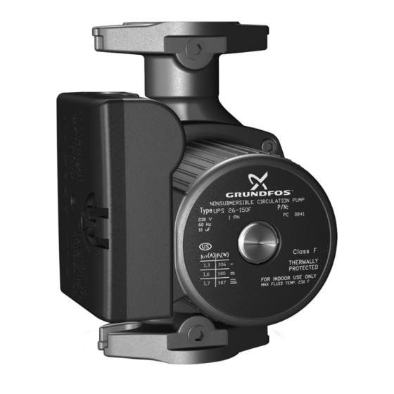
• Read the pump nameplate to ensure it is the installer to install, begin operation of, and one you ordered. troubleshoot the Grundfos Small UP and UPS • Compare the pump's nameplate data and its pumps. performance curve (for head, gpm, etc.) with Following the instructions will ensure safe, the application in which you plan to install it. -
Page 5: Verify Electrical Requirements
Warning Max. < 149 °F (65 °C) 100 °F (38 °C) The Grundfos Small UP/UPS pump is intended for use with water only. In domestic hot-water systems, it is The pump must not be used for the recommended to keep the liquid... -
Page 6: Installation Procedures
2. When installing the pump into the piping system, Grundfos recommends that pressure gauges be installed in the inlet and discharge flanges or pipes. This will allow the pump and system performance to be checked. -
Page 7: Changing The Terminal Box Position
5.2 Changing the terminal box position 6. Check to ensure the rotor turns freely. Do this by removing the vent plug in the middle of the pump nameplate. Insert a Warning medium-size, flat-blade screwdriver into the Before starting any work on this slot at the exposed end of the shaft. -
Page 8: Electrical Connection
5.3 Electrical connection • An external "Drip Loop" is recommended in the electrical wiring harness; see fig. 2. Warning • Where an external "Drip Loop" is not possible, or if the wiring enters through the Risk of electrical shock! The upward facing (top) surface of the box, then electrical connection and an internal "Drip Loop"... -
Page 9: Insulating Shells (If Equipped)
5.4 Insulating shells (if equipped) Do not block weep slots For pumps with provided insulation shell, the following procedures are required to insure safe and proper installation. 1. Pump and mating piping flange bolts need to be installed towards the pump as illustrated in fig. -
Page 10: Starting The Pump
6. Starting the pump 6.2 Speed selection UPS models 6.1 Vent the piping system Speeds can be changed via the speed switch on After the pump has been installed and the the terminal box cover. Power must be turned off electrical connections made, the piping system before changing speeds. -
Page 11: Fault Finding
7. Fault finding 7.1 Fault finding chart Warning Before removing the terminal box cover, make sure that the electrical supply has been switched off and that it cannot be accidentally switched on. Warning The pumped liquid may be scalding hot and under high pressure. Before any removal or dismantling of the pump, the system must be drained or the isolation valves on both sides of the pump must be closed. -
Page 12: Preliminary Checks
7.2 Preliminary checks 7.3 Current measurement To check the current using an ammeter, follow Supply voltage these steps: To check the voltage being supplied to the 1. Make sure the pump is operating. motor, use a voltmeter. 2. Set the ammeter to the proper scale. Warning 3. -
Page 13: Insulation Resistance (Lead-To-Ground)
7.4 Insulation resistance 7.6 Resistance tables (lead-to-ground) Checking connections in the terminal box at the power connections L and N; see fig. for 115 V To check the insulation resistance and 208-230 V. (lead-to-ground) of the motor and leads, use a megohmmeter and follow these steps: Ohm value 1. -
Page 14: Replacing Components
8. Replacing components Checking at the pin connection behind the terminal box (see section 8.3 Replacing the terminal box or capacitor for terminal box Warning removal): Before starting any work on this circulator, make sure electrical Stator pin supply has been switched off and Winding groups connection that it cannot be accidentally... -
Page 15: Fitting The Pump Head
8.2 Fitting the pump head 1. Carefully remove the new pump head 7. Check to make sure the rotor turns freely. Do assembly from its packaging. Separate the this by removing the vent plug in the middle impeller/rotor assembly from the new pump of the pump nameplate. -
Page 16: Replacing The Terminal Box Or Capacitor
8.3 Replacing the terminal box or capacitor Warning Before starting any work on this circulator, make sure electrical supply has been switched off and that it cannot be accidentally switched on. Removal 1. Before replacing the terminal box and capacitor, make sure the power is OFF. 2. -
Page 17: Additional Technical Data
1. Use the public or private waste collection service. Motor protection: Thermally protected 2. If this is not possible, contact the nearest Enclosure class: CSA Type 2 Grundfos company or service workshop. Insulation class: H Max. discharge Subject to alterations. 145 psi (10 bar) pressure: Max. - Page 19 GRUNDFOS Kansas City GRUNDFOS Canada GRUNDFOS México 17100 West 118th Terrace 2941 Brighton Road Boulevard TLC No. 15 Olathe, Kansas 66061 Oakville, Ontario L6H 6C9 Canada Parque Industrial Stiva Aeropuerto Phone: (913) 227-3400 Phone: +1-905 829 9533 C.P. 66600 Apodaca, N.L. México...
- Page 20 L-UP-TL-062 98419789 0715 ECM: 1161312 www.grundfos.com...
Need help?
Do you have a question about the UPS 26-150 and is the answer not in the manual?
Questions and answers