Fusion Apollo MS-RA670 Installation Instructions Manual
Hide thumbs
Also See for Apollo MS-RA670:
- Quick start manual (85 pages) ,
- Owner's manual (22 pages) ,
- Installation instructions manual (6 pages)
Advertisement
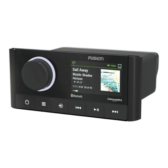
Apollo
MS-RA670 Installation
™
Instructions
Important Safety Information
Failure to follow these warnings and cautions could result in
personal injury, damage to the vessel, or poor product
performance.
See the Important Safety and Product Information guide in the
product box for product warnings and other important
information.
This device must be installed according to these instructions.
Disconnect the vessel's power supply before beginning to install
this product.
Before applying power to this product, make sure it has been
correctly grounded, following the instructions in the guide.
Always wear safety goggles, ear protection, and a dust mask
when drilling, cutting, or sanding.
When drilling or cutting, always check what is on the opposite
side of the surface.
Do not use the stereo as a template when drilling the mounting
holes because this may damage the glass display and void the
warranty. You must only use the included template to correctly
drill the mounting holes.
You must read all installation instructions before beginning the
installation. If you experience difficulty during the installation,
contact FUSION
®
Product Support.
What's In the Box
• Mounting gasket
• Four 8-gauge, self-tapping screws
• Two screw covers
• Power and speaker wiring harness
• Auxiliary-in, line-out, and subwoofer-out wiring harnesses
• Dust cover
Tools Needed
• Phillips screwdriver
• Electric drill
• Drill bit (size varies based on surface material and screws
used)
• Rotary cutting tool or jigsaw
• Silicone-based marine sealant (optional)
Mounting Considerations
• The stereo must be mounted on a flat surface.
• The stereo must be mounted in a location that allows open
airflow around the rear of the stereo for heat ventilation.
• If you are installing the stereo in a location that may be
exposed to water, it must be mounted within 45 degrees of
the horizontal plane.
• If you are installing the stereo in a location that may be
exposed to water, the cable should have a drip loop to allow
water to drip down off the cable and avoid damage to the
stereo.
®
WARNING
CAUTION
NOTICE
• If you need to mount the stereo outside a boat, it must be
mounted in a location far above the waterline, where it is not
submerged.
• If you need to mount the stereo outside a boat, it should be
mounted in a location where it cannot be damaged by docks,
pilings, or other pieces of equipment.
• To avoid interference with a magnetic compass, the stereo
should be installed at least 20 cm (7.87 in.) away from a
compass.
Mounting the Stereo
Do not use the stereo as a template when drilling the mounting
holes because this may damage the glass display and void the
warranty. You must only use the included template to correctly
drill the mounting holes.
Be careful when cutting the hole to mount the stereo. There is
only a small amount of clearance between the case and the
mounting holes, and cutting the hole too large could
compromise the stability of the stereo after it is mounted.
Be careful when installing the stereo in an aluminum boat or a
boat with a conductive hull, if you require the electrical system to
be isolated from the boat hull.
Do not apply grease or lubricant to the screws when fastening
the stereo to the mounting surface. Grease or other lubricants
can cause damage to the stereo housing.
Before you can mount the stereo in a new location on the
mounting surface, you must select a location in accordance with
the mounting considerations.
1
Trim the template and make sure it fits at the mounting
location.
2
Adhere the template to the mounting surface.
3
Using a drill bit appropriate for the mounting surface, drill a
hole inside the corner of the dashed line on the template to
prepare the mounting surface for cutting.
4
Using a rotary-cutting tool, cut the mounting surface along
the inside of the dashed line on the template.
5
Place the stereo in the cutout
6
If necessary, use a file and sandpaper to refine the size of
the cutout.
7
After the stereo fits correctly in the cutout, ensure the
mounting holes on the stereo line up with the pilot holes on
the template.
8
If the mounting holes on the stereo do not line up, mark the
new pilot-hole locations.
9
Using an appropriately sized drill bit for the mounting surface
and screw type, drill the pilot holes.
10
Remove the template from the mounting surface.
11
Make the necessary wiring connections
Considerations, page
2).
12
Select an option:
• If you are installing the stereo in a dry location, place the
included mounting gasket
NOTICE
to test the fit.
(Connection
on the back of the stereo.
April 2019
190-02516-91_0A
Advertisement
Table of Contents

Related Manuals for Fusion Apollo MS-RA670


Summary of Contents for Fusion Apollo MS-RA670
- Page 1 If you experience difficulty during the installation, prepare the mounting surface for cutting. contact FUSION ® Product Support. Using a rotary-cutting tool, cut the mounting surface along the inside of the dashed line on the template.
-
Page 2: Connection Considerations
You can enable this included). functionality from the settings menu. Connects to a FUSION DAB module to receive DAB stations where available (not included). Orange Connects to the boat's illumination wire to dim the stereo screen when... -
Page 3: Connecting To Power
If you have already connected a USB source, disconnect it or to add an another fuse to the red wire. from the stereo. Apollo MS-RA670 Installation Instructions... - Page 4 PartyBus network, you must connect the stereo to the FUSION NMEA 2000 System Wiring Diagram PartyBus network using a wired ethernet connection, and then connect a Wi‑Fi access point or router to the FUSION PartyBus network. A FUSION PartyBus stereo, such as the Apollo RA670 stereo, can stream sources to other FUSION PartyBus stereos connected to the network.
-
Page 5: Network Troubleshooting
Test the network by viewing the list of FUSION PartyBus devices from each device on the network and select an option: • If any FUSION PartyBus devices are not available to the network, troubleshoot the network (Network Troubleshooting, page • If all FUSION PartyBus devices are available to the network, complete the installation for each stereo, if necessary. -
Page 6: Software Updates
USB flash drive, go to the device product page at www.fusionentertainment.com/marine. Side Dimensions If the stereo is connected to a FUSION PartyBus network with a Wi‑Fi router, you can also update the software using the FUSION-Link ™...
Need help?
Do you have a question about the Apollo MS-RA670 and is the answer not in the manual?
Questions and answers