Advertisement
Quick Links
Mounting Instructions 82021 Code-Combi K
1 General
These mounting instructions are the basis for the approval by ECBS, VdS installation of the lock to be performed
exclusively in accordance with these instructions.
Guidelines of the national certification bodies are to be considered and complied with in addition.
Use high quality alkaline/manganese monobloc batteries only. Low quality batteries may cause oxidation which results in a
functional failure of the lock..
Avoid residual crystalline moisture in the cabinet (e.g. from varnishing) to make sure that electrical contact areas are not
attacked.
Make sure that the ingress of dirt or detergents (e.g. remaining fillers or cold cleaners) is prevented.
Do not grease/oil the lock or key.
It is recommended, that unauthorized persons have no access to security sensitive parts of the lock, also the door of the
safe, where the lock is installed, is open.
2 Mounting instructions for lock and control unit
Bolt left
Bolt down
Bolt up
Bolt right
Any variation of the lock or key may result in functional trouble and must better not be done. All claims under guarantee and
warranty will expire in this case.
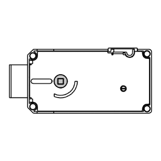
Lock fastening: Use of M6 steel socket head cap screws or BSW ¼" steel bolts. The length of engagement must
correspond to the applicable standards considering the thickness of the lock height (see Fig. 1).
Fig.1
Lock mounting position
Stand 17.02.2016
Seite 1 von 12
Advertisement

Related Manuals for Kaba Mauer Code-Combi K 82021


Summary of Contents for Kaba Mauer Code-Combi K 82021
- Page 1 Mounting Instructions 82021 Code-Combi K 1 General These mounting instructions are the basis for the approval by ECBS, VdS installation of the lock to be performed exclusively in accordance with these instructions. Guidelines of the national certification bodies are to be considered and complied with in addition. ...
-
Page 2: Technical Data
This can be achieved by mounting the lock according to the following pattern of mounting holes (page 5 and following). For further lock dimensions please refer to the Kaba Mauer Catalogue Sheet. Technical data: ... - Page 3 Mounting Instructions 82021 Code-Combi K Cable cover 3 Assembly Connecting sleeve Fig. 3: Exploded view 82021Code-Combi K Door Connecting cover ➁ Connecting cable ➂ ➀ ➃ ➄ ➀ Fixing input unit. Insert the input unit’s connecting cable through the door of the safe. Care must be taken to ensure that the connecting cable is not damaged during installation.
- Page 4 Mounting Instructions 82021 Code-Combi K 5 Assembly Diagrams Installation position of lock Installation position of input unit Hole dimensions of input unit Cable-lead through R iegel oben K nopf oben Screw fixing points for lock Stand 17.02.2016 Seite 4 von 12...
- Page 5 Mounting Instructions 82021 Code-Combi K Installation position of lock Installation position of input unit R iegel links K n opf links 83 ,5 Hole dimensions of input unit Cable-lead through 23 ,5 R iegel oben Screw fixing points for lock Stand 17.02.2016 Seite 5 von 12...
- Page 6 Mounting Instructions 82021 Code-Combi K Installation position of lock Installation position of input unit R iegel rechts K n opf rechts 23,5 Hole dimensions of input unit 83,5 Cable-lead through R iegel oben Screw fixing points for lock Stand 17.02.2016 Seite 6 von 12...
- Page 7 Mounting Instructions 82021 Code-Combi K Installation position of lock Installation position of input unit R iegel links K n opf links 83 ,5 Hole dimensions of input unit Cable-lead through 23 ,5 Screw fixing points for lock R ieg el u n ten Stand 17.02.2016 Seite 7 von 12...
- Page 8 Mounting Instructions 82021 Code-Combi K Installation position of lock Installation position of input unit R iegel rechts K n opf rechts 23,5 Hole dimensions of input unit R iegel rechts K n opf rechts 83,5 Cable-lead through 23,5 83,5 Screw fixing points for lock R ieg el u n ten Stand 17.02.2016 Seite 8 von 12...
- Page 9 Mounting Instructions 82021 Code-Combi K Installation position of lock Installation position of input unit K nopf u nten Cable-lead through Hole dimensions of input unit R iegel lin ks 33 ,6 1 04,5 Screw fixing points for lock Stand 17.02.2016 Seite 9 von 12...
- Page 10 Mounting Instructions 82021 Code-Combi K Installation position of lock Installation position of input unit R iegel links K n opf links 83 ,5 Hole dimensions of input unit Cable-lead through 23 ,5 R iegel lin ks 33 ,6 1 04,5 Screw fixing points for lock Stand 17.02.2016 Seite 10 von 12...
- Page 11 Mounting Instructions 82021 Code-Combi K Installation position of lock Installation position of input unit K nopf u nten Cable-lead through Hole dimensions of input unit R iegel rechts 1 04,5 33,6 Screw fixing points for lock Stand 17.02.2016 Seite 11 von 12...
- Page 12 Mounting Instructions 82021 Code-Combi K Installation position of lock Installation position of input unit R iegel rechts K n opf rechts 23,5 Hole dimensions of input unit 83,5 Cable-lead through R iegel rechts 1 04,5 33,6 Screw fixing points for lock Stand 17.02.2016 Seite 12 von 12...
Need help?
Do you have a question about the Code-Combi K 82021 and is the answer not in the manual?
Questions and answers