
Related Manuals for Orolia VersaSync


Summary of Contents for Orolia VersaSync
- Page 1 VersaSync User Manual Document Part No.: 1228-5000-0050 Revision: 7.0 Date: 5-August-2019 orolia.com...
- Page 3 Orolia reserves the right to make changes to the product described in this doc- ument at any time and without notice. Any software that may be provided with the product described in this document is furnished under a license agreement or nondisclosure agreement.
- Page 4 Blank page. VersaSync User Manual...
- Page 5 1.7 VersaSync Specifications 1.7.1 Supply Power 1.7.2 GNSS Receiver 1.7.3 Mechanical & Environmental Specifications 1.7.3.1 Physical Specifications 1.7.3.2 Environmental Requirements 1.8 Regulatory Compliance 1.9 The VersaSync Web UI 1.9.1 The Web UI HOME Screen VersaSync User Manual • TABLE OF CONTENTS...
-
Page 6: Table Of Contents
2.7.2.1 How to Configure an Input Reference 2.7.2.2 How to Configure an Output 2.7.3 Example: Configuring a 20 PPS Output 2.7.4 Configurable I/Os 2.7.4.1 Configuring a 1PPS Input 2.7.4.2 Configuring a 1PPS Output VersaSync User Manual • TABLE OF CONTENTS... - Page 7 2.8.9.3 Dis-/Enabling NTP 2.8.9.4 Viewing NTP Clients 2.8.9.5 Restoring the Default NTP Configuration 2.8.9.6 NTP Output Timescale 2.8.9.7 NTP Reference Configuration 2.8.9.8 NTP Servers and Peers 2.8.9.9 NTP Authentication 2.8.9.10 NTP Access Restrictions VersaSync User Manual • TABLE OF CONTENTS...
- Page 8 3.3.1 Input Reference Priorities 3.3.1.1 Configuring Input Reference Priorities 3.3.1.2 The "Local System" Reference 3.3.1.3 The "User/User" Reference 3.3.1.4 Reference Priorities: EXAMPLES 3.3.2 Reference Qualification and Validation 3.3.2.1 BroadShield 3.3.3 The GNSS Reference VersaSync User Manual • TABLE OF CONTENTS...
- Page 9 4.3.4 Setting Up SNMP Notifications 4.3.5 Setting Up Email Notifications 4.4 Managing Users and Security 4.4.1 Managing User Accounts 4.4.1.1 Types of Accounts 4.4.1.2 About "user" Account Permissions 4.4.1.3 Rules for Usernames 4.4.1.4 Adding/Deleting/Changing User Accounts VersaSync User Manual • TABLE OF CONTENTS...
- Page 10 4.8.2.2 Saving the System Configuration Files 4.8.2.3 Uploading Configuration Files 4.8.2.4 Restoring the System Configuration 4.8.2.5 Restoring the Factory Defaults 4.8.3 Cleaning the Configuration Files and Halting the System 4.8.4 Default and Recommended Configurations VIII VersaSync User Manual • TABLE OF CONTENTS...
- Page 11 5.3.4.1 VNYPR 5.3.4.2 VNQTN 5.3.4.3 VNQMR 5.3.4.4 VNMAG 5.3.4.5 VNACC 5.3.4.6 VNGYR 5.3.4.7 VNMAR 5.3.4.8 VNYMR 5.3.4.9 VNYBA 5.3.4.10 VNYIA 5.3.4.11 VNIMU 5.3.4.12 VNGPS 5.3.4.13 VNGPE 5.3.4.14 VNINS 5.3.4.15 VNINE 5.3.4.16 VNISL 5.3.4.17 VNISE VersaSync User Manual • TABLE OF CONTENTS...
- Page 12 5.4 IRIG Standards and Specifications 5.4.1 About the IRIG Output Resolution 5.4.2 IRIG Carrier Frequencies 5.4.3 IRIG B Output 5.4.4 IRIG E Output 5.4.5 IRIG Output Accuracy Specifications 5.5 Subnet Mask Values 5.6 Product Registration VersaSync User Manual • TABLE OF CONTENTS...
- Page 13 5.7 Technical Support 5.7.1 Regional Contact 5.8 Return Shipments 5.9 License Notices 5.9.1 NTPv4.2.8p12 5.9.2 OpenSSH 5.9.3 OpenSSL 5.10 List of Tables 5.11 List of Images 5.12 Document Revision History INDEX VersaSync User Manual • TABLE OF CONTENTS...
- Page 14 BLANK PAGE. VersaSync User Manual • TABLE OF CONTENTS...
-
Page 15: Spectracom Format
Product Description The Chapter presents an overview of the VersaSync Time and Frequency Synchronization System, its capabilities, main tech- nical features and specifications. The following topics are included in this Chapter: 1.1 Getting Started 1.2 VersaSync Overview 1.3 Status LEDs 1.4 Interfaces Overview... - Page 16 Figure 1-1: VersaSync Rugged GPS Time & Frequency Reference Welcome to the VersaSync User Manual . First steps: If you are not yet familiar with VersaSync, you may want to start here: "VersaSync Overview" below. If you are ready to begin the installation process, see: "Initial Network Setup"...
- Page 17 I/O pins can be configured as TTL, 10 V pulse, RS232, RS422, and RS485. This allows VersaSync to provide a high number of outputs of the same type, while still fitting into a small form factor. However, if the combination of software con-...
- Page 18 1.3 Status LEDs Status LEDs VersaSync's front panel status LEDs provide a real-time status overview: Eight (8) LEDs indicate the unit's current operating state: The LEDs can be disabled, see "Blackout Mode" on page 6. 1.3.1 Blinking Intervals The status LEDs can communicate five different operating states: "OFF"...
- Page 19 Unit is in Holdover (valid) System Clock OK (valid) FAST Invalid Time (Holdover period exceeded, or oscillator damaged) No output signal(s) detected/all outputs are disabled FAST Malfunction detected (short circuit, or overload) Outputs are enabled CHAPTER 1 • VersaSync User Manual Rev. 7.0...
- Page 20 Navigate to MANAGEMENT > OTHER: LED Configuration, and set the Brightness level to "0". Interfaces Overview All of VersaSync's interfaces are integrated into the unit's connectors, which are located on the front panel: CHAPTER 1 • VersaSync User Manual Rev. 7.0...
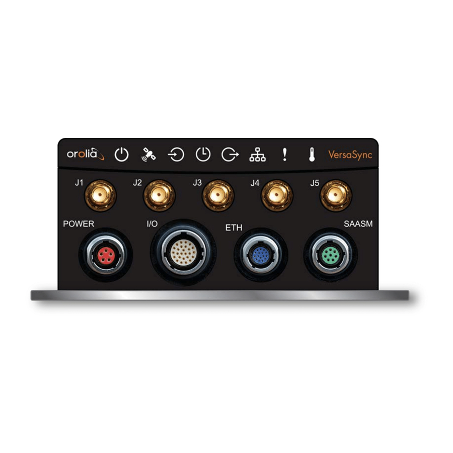
- Page 21 1.4 Interfaces Overview Figure 1-2: VersaSync front panel connectors Note: VersaSync is highly configurable and the connections can be adjusted many different ways. Your interface configuration may vary based on options you selected during the ordering process. The following interfaces are provided: 1.4.1...
- Page 22 For additional information on configuring pinouts, see "Connectors and their Pinouts" on the facing page "Configure I/O Input and Output Settings" on page 44. 1.4.3 Other Interfaces USB serial equivalent: CLI interface (Connector 4) CHAPTER 1 • VersaSync User Manual Rev. 7.0...
- Page 23 1.5 Connectors and their Pinouts Connectors and their Pinouts All of VersaSync's connectors are provided at the front panel of the unit, below the Status LEDs. The Advanced Military Connectors are keyed for foolproof connectivity and offer a push-pull locking mechanism.
- Page 24 1.5.2 Input/Output Connector VersaSync has a 26- pin input/output connector that offers 8 software- configurable CHANNELS, plus one fixed DCLS channel, and a USB interface. To learn more about types of interfaces and signals, and how to configure them, see "Assigning I/O Pins"...
- Page 25 The Optional I/O connector is used in conjunction with the Option Board that is available for VersaSync. If the unit is not equipped with an Option Board, this connector is not used. CHAPTER 1 • VersaSync User Manual Rev. 7.0...
- Page 26 1.5 Connectors and their Pinouts 1.5.5 Coaxial Connectors VersaSync offers five (5) coaxial connectors, three (3) of which can be configured at the factory to accommodate requirements for e.g., IRIG AM signals or additional 10 MHz out- puts. The minimum configuration includes the...
- Page 27 POWER connector pinout 1: V , 10 to 32 V Main 2: -not used- 3: V , 10 to 32 V (Standby Power) Standby 4: Ground return, standby power 5: Ground return, main power CHAPTER 1 • VersaSync User Manual Rev. 7.0...
- Page 28 1.6 Included Cables Included Cables The VersaSync Evaluation Kit contains the following cables (antenna cable not shown): Power Cable I/O Cable CHAPTER 1 • VersaSync User Manual Rev. 7.0...
- Page 29 1.6 Included Cables I/O Breakout Cable Ethernet Data Cable CHAPTER 1 • VersaSync User Manual Rev. 7.0...
- Page 30 32V require an external power conditioner/power filter to ensure safe operation. 1.7.2 GNSS Receiver VersaSync has an integrated state-of-the-art GNSS receiver, suitable for concurrent dual- constellation reception. Compatible signals: GPS L1 C/A (center frequency 1575.42 MHz) GLONASS L1 0F (center frequency 1602.0 MHz)
- Page 31 Weight: 0.91 kg (2.0 lbs) 1.7.3.2 Environmental Requirements Temperature, in operation: -40°C to +71°C Temperature, in storage: -45°C to +85°C Humidity: 95% RH, non condensing at 40°C Altitude: up to 45,000 ft CHAPTER 1 • VersaSync User Manual Rev. 7.0...
- Page 32 (Curve #2) MIL-STD-461F RE102 Radiated Emissions, Electric Field Note: Frequency Range: 10 kHz to 18 GHz; Test Limits: Figure RE102- MIL-STD-461F CS114 Conducted Susceptibility, Bulk Cable Injection Note: Frequency Range: 10 kHz to 200 MHz FCC compliance CHAPTER 1 • VersaSync User Manual Rev. 7.0...
- Page 33 RoHS, WEEE compliant. The VersaSync Web UI VersaSync has an integrated web user interface (referred to as "Web UI" throughout this documentation) that can be accessed from a network-connected computer, using a stand- ard web browser. The Web UI is the most complete way to configure and monitor the unit.
-
Page 34: The Interfaces Menu
TOOLS: Opens a drop-down menu for access to the system maintenance screens and system logs. HELP: Provides Spectracom Service Contact Information and high-level system con- figurations you may be required to furnish when contacting Orolia Service. 1.9.2 The INTERFACES Menu... -
Page 35: The Configuration Management Menu
1.9.3 The Configuration MANAGEMENT Menu MANAGEMENT menu on the Web UI's Main screen provides access to VersaSync's configuration screens and settings. On the left side, under NETWORK, the following standard setup screens can be found: Layout... -
Page 36: The Tools Menu
1.9 The VersaSync Web UI Notifications: Configure the notifications triggered by VersaSync’s events. A noti- fication can be a combination of a mask alarm and/or SNMP Trap and/or email. Time Management: Manage the Local Clock, UTC Offset, DST Definition and Leap Second information. -
Page 37: Setup
The following topics are included in this Chapter: 2.1 SAFETY 2.2 Installation Overview 2.3 Initial Network Setup 2.4 Accessing the Web UI 2.5 Zero Configuration Setup 2.6 Setting up an IP Address 2.7 Configuring Inputs/Outputs 2.8 Configuring Network Settings CHAPTER 2 • VersaSync User Manual... -
Page 38: Safety
Before you begin installing and configuring this product, carefully read the following import- ant safety statements. Always ensure that you adhere to any and all applicable safety warn- ings, guidelines, or precautions during the installation, operation, and maintenance of your product. CHAPTER 2 • VersaSync User Manual Rev. 7.0... -
Page 39: Safety: User Responsibilities
Use only spare parts authorized by Spectracom. Always follow the instructions set out in this User Manual , or in other Spectracom documentation for this product. Observe generally applicable legal and other local mandatory regulations. CHAPTER 2 • VersaSync User Manual Rev. 7.0... -
Page 40: Safety: Other Tips
Clearly mark the equipment to prevent its further operation. Installation Overview The steps that need to be performed prior to putting VersaSync into service include: Installation: Hardware setup, mechanical installation, physical connections. Setup: Establish basic access to the unit, so as to allow the use of the web user inter- face ("Web UI"). - Page 41 PC a network. (CA08R-CRET-0002) USB: Connect the Multi I/O connector to the VersaSync unit. If you are using the Evaluation Kit, connect the Multi I/O USB output to a PC. Install a ter- ® ®...
-
Page 42: Mounting
2.2 Installation Overview 6. Using the Web UI, configure the following: Software-configurable I/O pins, see "Assigning I/O Pins" on page 39. Other VersaSync INTERFACES settings and MANAGEMENT settings e.g., network settings, reference priorities (see "Configuring Network Settings" page 62). 2.2.2 Mounting 2.2.2.1 Selecting a Mounting Location The unit is to be mounted on a plate, using six (6) through holes. -
Page 43: Heat Dissipation
DC of the power source becomes the ground of the chassis. Typical AC "earth ground" measures are unnecessary because of this design. Should you opt to ground your VersaSync directly to your vehicle, connect the DC neg- ative terminals of the power connector to the chassis of the unit and to the vehicle metallic structure. -
Page 44: Usb Driver
IP address on your network. (See "Assigning a Static IP Address" on page 36). Default settings: VersaSync network settings default to static IP addresses. The Ethenet ports come pre- configured with IP addresses as follows: Eth0 - 192.168.1.1 Eth1 - 192.168.1.2 Default subnet mask: 255.255.255.0 2.3.1... - Page 45 Access the CLI via ssh or telnet: The required port configuration is 115200 8N1: Press the Return key, and enter the login credentials: Note: The default login credentials are: User name = spadmin Password = admin123 (will not be displayed on the screen) CHAPTER 2 • VersaSync User Manual Rev. 7.0...
-
Page 46: Accessing The Web Ui
IP address. You can use this IP address to login to the VersaSync Web UI and then set a static IP address, subnet mask and gateway. (This can also be done via the CLI and a terminal emulator. - Page 47 DHCP IP address, or by using a manually set static IP address (see "Assigning a Static IP Address" on page 36). 1. On a PC connected to VersaSync via ETH1 or ETH0, start a web browser. 2. Navigate to the IP address assigned or identified in "Initial Network Setup" on page 29.
-
Page 48: Zero Configuration Setup
(DHCP must be enabled through the Web UI or CLI) in circumstances when your unit is not connected directly to a PC when you wish to access the Web UI of your VersaSync without using the CLI com- mands or serial connection... -
Page 49: Using Zeroconf
Setting up an IP Address In order for VersaSync to be accessible via your network, you need to assign an IP address to VersaSync, as well as a subnet mask and gateway, unless you are using an address assigned by a DHCP server. -
Page 50: Assigning A Static Ip Address
By default, the gateway is dis- abled. 2.6.1 Assigning a Static IP Address There are two ways to setup a permanent static IP address, after connecting VersaSync to a network: Assigning a Static IP Address Using the CLI: Note:... - Page 51 ("Initial Network Setup" on page 29) into the address field of your browser (on a computer connected to the VersaSync network). If the network supports DNS, the hostname may also be entered instead (the default hostname is "Spectracom"). The start screen of the VersaSync Web UI will be displayed.
-
Page 52: Configuring Inputs/Outputs
"The GNSS Reference" on page 171 in the Chapter MANAGING TIME. Note: The Network Ports eth0 eth1 can be configured under MANAGEMENT > Network Setup. For more information, see "Configuring Network Settings" on page 62. CHAPTER 2 • VersaSync User Manual Rev. 7.0... -
Page 53: Assigning I/O Pins
2.7 Configuring Inputs/Outputs 2.7.1 Assigning I/O Pins VersaSync's I/O connector is software configurable, i.e. the pin interfaces and the signal modulations can be configured by the user via the VersaSync Web UI. The software-configurable 26-pin I/O connector comprises 9 user-configurable Channels, plus one fixed USB interface. -
Page 54: Signal Types
DCLS outputs and three DCLS inputs are available for e.g., 1PPS, xPPS, IRIG, HaveQuick, ASCII ToD signal transmission. Single-ended Serial Lines VersaSync provides up to 3 RX and 3 TX RS232 interfaces for e.g., ASCII ToD – NMEA 0183 (ICD-GPS-153). - Page 55 = This Signal Message type cannot be assigned to this Channel = ASCII Time Code Configuring a new Input or Output 1. In the VersaSync Web UI, navigate to MANAGEMENT > NETWORK: Pin Layout. Pin Layout screen will be displayed.
- Page 56 Apply Changes. Restoring the Default I/O Configuration VersaSync is shipped with a default I/O configuration that you can be customized. However, if required you can restore the default configuration at any time after applying changes. The following illustration shows the...
- Page 57 To reload the currently used I/O configuration after adding pin layout changes, but before clicking Apply Changes: A. Navigate to the MANAGEMENT: NETWORK > Pin Layout screen. B. In the Actions panel on the left, click Reload Layout. CHAPTER 2 • VersaSync User Manual Rev. 7.0...
-
Page 58: Configure I/O Input And Output Settings
2. In the Status window, click the GEAR button next to the desired input reference. 3. The settings window for the chosen reference will be displayed. Edit the field(s) as desired. For more information, see "Managing References" on page 153. CHAPTER 2 • VersaSync User Manual Rev. 7.0... -
Page 59: How To Configure An Output
The instructions below explain how to configure a 20 PPS output signal: First, assign a GPIO output to an I/O pin pair: 1. In the Web UI, navigate to MANAGEMENT > NETWORK: Pin Layout. The Pin Lay- screen will be displayed. CHAPTER 2 • VersaSync User Manual Rev. 7.0... - Page 60 Output Mode Square Wave, and check Output Enabled. 12. To configure e.g., a 20 PPS signal, set the Pulse Width to 1 000 000 ns, and the Period to 50 000 000 ns: CHAPTER 2 • VersaSync User Manual Rev. 7.0...
-
Page 61: Configurable I/Os
To configure a 1PPS Input: 1. Navigate to INTERFACES > REFERENCES: PPS Input 0 (or: INTERFACES > OPTION CARDS: PPS Input 2. The PPS Input 0 Status window displays. Click Edit to open the configuration win- dow: CHAPTER 2 • VersaSync User Manual Rev. 7.0... -
Page 62: Configuring A 1Pps Output
1PPS Output Edit window will display, allowing the following items to be con- figured: Signature Control : Determines when the output is enabled. For more inform- ation, see "Signature Control" on page 60. CHAPTER 2 • VersaSync User Manual Rev. 7.0... -
Page 63: Configuring An Ascii Input
Reference ID, input Validity, ASCII Format, and if a pending Leap Second will be added to the UTC timescale at the end of the month. (See also "Local Clock(s), DST" on page 149.) 2. Click Edit to open the configuration window: CHAPTER 2 • VersaSync User Manual Rev. 7.0... - Page 64 Note: Auto is chosen as the format group, the format will automatically be Auto- detect. VersaSync will attempt to identify the format of the incoming ASCII message. Offset: Provides the ability to account for ASCII input cable delays or other latencies in the ASCII input.
-
Page 65: Configuring An Ascii Output
Configuring an ASCII Output About the ASCII Format Outputs The ASCII outputs (ATC = ASCII Time Code) provide VersaSync with the ability to output one, two or three back-to-back ASCII time code data streams that can be provided to peri- pheral devices which accept an ASCII RS-232 or RS-485 input data stream for either their external time synchronization or for data processing. - Page 66 The on-time points for the second and third mes- sages that are provided at the same time as the first message are discarded. This unique capability allows VersaSync to be able to simultaneously provide multiple pieces of data from different selected format messages.
- Page 67 Timescale: Used to select the time base for the incoming data. The entered Timescale is used by the system to convert the time in the incoming data stream to UTC time for use by the System Time. The available choices are: CHAPTER 2 • VersaSync User Manual Rev. 7.0...
-
Page 68: Event Broadcast (Ascii Output)
ASCII messages are stored in a Message Buffer . The message buffer can store 512 entries before overflowing. Messages may be lost if the buffer overflows. Messages can be output in one of two ways: CHAPTER 2 • VersaSync User Manual Rev. 7.0... - Page 69 3. Click the Edit button to open the configuration window: Event Capture: Enables the processing of events on the Event Input (pins 11 & 12). When set to “Disabled”, no event messages will be queued. When set CHAPTER 2 • VersaSync User Manual Rev. 7.0...
- Page 70 For more information on Signature Control, see "Signature Control" on page 60. Format: Selects the format of the message to be outputted. Refer to "Event Broadcast Time Code Formats" on page 327 for a description of all of the CHAPTER 2 • VersaSync User Manual Rev. 7.0...
-
Page 71: Configuring A Havequick Input
August-2019, this is 18 seconds ahead of UTC time) Request character: This field defines the character that VersaSync needs to receive in order for a message to be provided when in “Request” mode. This field will only appear if the Output Mode is set as “Request Broadcast.”... - Page 72 Time Management Page; see "Local Clock (s), DST" on page 149. Local timescale allows a Local Clock to apply a time offset for Time Zone and DST correction. CHAPTER 2 • VersaSync User Manual Rev. 7.0...
-
Page 73: Configuring A Havequick Output
: The user- selectable format to be used. Available formats include: STANAG 4246 HQI STANAG 4246 HQII STANAG 4372 HQIIA STANAG 4430 STM STANAG 4430 XHQ ICD-GPS-060A BCD ICD-GPS-060A HQ DOD-STD-1399 BCD CHAPTER 2 • VersaSync User Manual Rev. 7.0... -
Page 74: Signature Control
You can setup Signature Control such that VersaSync's built in 1PPS output becomes disabled the moment its input reference is lost (e.g., if a valid GNSS signal is lost). Or, you can setup your output signal such that remains valid while VersaSync in holdover mode, but not in free run. - Page 75 (the output is NOT present while VersaSync is in Holdover mode.) Output Always Disabled—The output is never present, even if VersaSync ref- erences are present and valid. Table 2-4: Signature control output-presence states...
-
Page 76: Configuring Network Settings
2.8 Configuring Network Settings Changing Signature Control via the Front Panel The VersaSync front panel allows you to change the signature control between two states: Output Always Enabled and Output Always Disabled. For more options and control over the Signature Control setting, you must use the Web UI (see above). -
Page 77: General Network Settings
Login Banner: Allows the administrator to configure a custom banner mes- sage to be displayed on the VersaSync Web UI login page and the CLI (Note: There is a 2000 character size limit). SSH: This button takes you to the SSH Setup window. -
Page 78: Network Ports
(showing the connection speed) Yellow: CABLE UNPLUGGED (the port is enabled but there is no cable attached) Red: DISABLED. Locate the port you want to configure (eth0 or eth1) and click the GEAR but- CHAPTER 2 • VersaSync User Manual Rev. 7.0... - Page 79 The default subnet is: 255.255.0.0 Netmask: This is the network subnet mask assigned by the network admin- istrator. In the form “ xxx.xxx.xxx.xxx.” See "Subnet Mask Values" on page 342 for a list of subnet mask values. CHAPTER 2 • VersaSync User Manual Rev. 7.0...
-
Page 80: Network Services
IPv4 Gateway : The gateway (default router) address is needed if com- munication to the VersaSync is made outside of the local network. By default, the gateway is disabled. Domain: This is the domain name to be associated with this port. -
Page 81: Access Rules
4. In the Allow From field, enter a valid IP address. It is not possible, however, to add direct IP addresses, but instead they must be input as blocks, i.e. you need to add CHAPTER 2 • VersaSync User Manual Rev. 7.0... -
Page 82: Https
TCP/IP protocol is used to transfer and display data securely by adding an encryption layer to protect the integrity and privacy of data traffic. Certificates issued by trusted authorities are used for sender/recipient authentication. Note: In order to configure HTTPS, you need ADMINISTRATOR rights. CHAPTER 2 • VersaSync User Manual Rev. 7.0... -
Page 83: Accessing The Https Setup Window
Certificate Authority. Upload X.509 PEM Certificate: Use the window under this tab to paste your X.509 certificate text and upload it to VersaSync. Upload Certificate File: Use this tab to upload your certificate file returned by the Certificate Authority. -
Page 84: About Https
PC. In order to establish a secure HTTPS connection, an SSL certificate must be stored inside the VersaSync unit. VersaSync uses the OpenSSL library to create certificate requests and self-signed cer- tificates. The OpenSSL library provides the encryption algorithms used for secure HTTP (HTTPS). -
Page 85: Supported Certificate Formats
2.8 Configuring Network Settings 2.8.5.3 Supported Certificate Formats VersaSync supports X.509 PEM and DER Certificates, as well as PKCS#7 PEM and DER formatted Certificates. You can create a unique X.509 self-signed Certificate, an RSA private key and X.509 cer- tificate request using the Web UI. RSA private keys are supported because they are the most widely accepted. - Page 86 2.8 Configuring Network Settings Note that an invalid Certificate may result in denial of access to VersaSync via the Web UI! 4. Fill in the available fields: Signature Algorithm: Choose the algorithm to be used from: SHA1 SHA256 SHA512 Private Key Pass Phrase: This is the RSA decryption key.
- Page 87 Certificate Authority. Note: It may take several minutes for VersaSync to create the Cer- tificate request and the private key (larger keys will require more time than small keys). If the unit is rebooted during this time, the Cer- tificate will not be created.
-
Page 88: Adding Https Subject Alternative Names
(or, navigate to MANAGEMENT > NETWORK Setup, and click HTTPS in the Actions panel. 2. In the Subject Alternative Name Extension tab, select the plus icon to access the Add Subject Alternative Name popup. CHAPTER 2 • VersaSync User Manual Rev. 7.0... -
Page 89: Requesting An Https Certificate
5. After adding all the desired Subject Alternative Names, follow instructions for "Creating an HTTPS Certificate Request" on page 71. 2.8.5.6 Requesting an HTTPS Certificate Before requesting an HTTPS Certificate from a third-party Certificate Authority, you need to create a Certificate Request: CHAPTER 2 • VersaSync User Manual Rev. 7.0... - Page 90 Using a Self-Signed Certificate In the process of generating a Certificate Request, a self- signed certificate will auto- matically be generated simultaneously. It will be displayed under the Certificate Request CHAPTER 2 • VersaSync User Manual Rev. 7.0...
-
Page 91: Uploading An X.509 Pem Certificate Text
Authority, or – if a Certificate Authority is not available – until it expires. The typical life span of a certificate is about 10 years. NOTE: When accessing the VersaSync Web UI while using the self-signed certificate, your ® Windows web browser will ask you to confirm that you want to access this site via https with only a self-signed certificate in place. -
Page 92: Uploading An Https Certificate File
Once the HTTPS Certificate has been issued by your Certificate Authority, you have to upload the Certificate file to VersaSync, unless it is a X.509 PEM-format Certificate: In this case you may also upload the pasted Certificate text directly, see "Uploading an X.509... -
Page 93: Ssh
Authority in its location where you stored it in step 1. 6. Click Submit. Note: VersaSync will automatically format the Certificate into the X.509 PEM format. Certificate Chain It is possible to upload a X.509PEM Certificate Chain file. Note that there should be no char- acter between the Certificate texts. - Page 94 The SSH tools supported by VersaSync are: SSH: Secure Shell SCP: Secure Copy SFTP: Secure File Transfer Protocol VersaSync implements the server components of SSH, SCP, and SFTP. For more information on OpenSSH, please refer to www.openssh.org To configure SSH: 1.
- Page 95 2.8 Configuring Network Settings VersaSync units have their initial host keys created at the factory. RSA host key sizes can vary between 768 and 4096 bits. The recommended key size is 1024. Though many key sizes are supported, it is recommended that users select key sizes that are powers of 2 or divisible by 2.
- Page 96 The Host keys are generated in the background. Creating RSA and DSA keys, each with 1024 bits length, typically takes about 30 seconds. Keys are created in the order of RSA, DSA, ECDSA, ED25519. VersaSync will gen- erate all 4 host keys, RSA, DSA, ECDSA, and ED25519.
- Page 97 3. Load a public key into VersaSync. This public key must match the private key found in the users account and be accessible to the SSH, SCP, or SFTP client program.
- Page 98 Creating an SSH session with Password Authentication for the admin account ssh spadmin@10.10.200.5 spadmin@10.10.200.5's password: admin123 You are now presented with boot up text and/or a “>” prompt which allows the use of the Spectracom command line interface. CHAPTER 2 • VersaSync User Manual Rev. 7.0...
- Page 99 Creating an SSH session using Public Key with Passphrase Authentication for the admin account You must first provide the secure Orolia product a RSA public key found typically in the OpenSSH id_rsa.pub file. Then you may attempt to create an SSH session.
-
Page 100: Snmp
You will be presented with the SFTP prompt allowing interactive file transfer and directory navigation. Recommended SSH Client Tools Orolia does not make any recommendations for specific SSH clients, SCP clients, or SFTP client tools. However, there are many SSH based tools available to the user at low cost or free. - Page 101 SNMP traps that Managers in other areas also receive. Clicking the PLUS icon in the top-right corner opens the SNMP Traps Settings Screen. See also "SNMP Traps" on page 94 "Setting Up SNMP Notifications" on page 215. CHAPTER 2 • VersaSync User Manual Rev. 7.0...
- Page 102 Description—A simple product description. This is not editable in the SNMP Status. Restoring the Default SNMP Configuration To restore the VersaSync to its default SNMP configuration: 1. Navigate to the MANAGEMENT > NETWORK: SNMP Setup screen. 2. In the...
- Page 103 Accessing the SNMP Support MIB Files Spectracom’s private enterprise MIB files can be extracted via File Transfer Protocol (FTP) from VersaSync, using an FTP client such as FileZilla or any other shareware/freeware FTP program. To obtain the MIB files from VersaSync via FTP/SFTP: 1.
-
Page 104: Snmp V1/V2C
In addition to the Spectracom MIB files, there are also some net- snmp MIB files provided. Net- snmp is the embedded SNMP agent that is used in the VersaSync and it provides traps to notify the user when it starts, restarts, or shuts down. These MIB files may also be compiled into your SNMP manager, if they are not already present. - Page 105 SNMP V1/V2 panel that displays the community you wish to edit or delete. The cursor will change from an arrow icon to a pointing finger to indic- ate that the entry is clickable. CHAPTER 2 • VersaSync User Manual Rev. 7.0...
-
Page 106: Snmp V3
Creating Users 1. Navigate to MANAGEMENT > NETWORK: SNMP Setup. 2. In the SNMP V3 panel, click the PLUS icon in the top-right corner. 3. The SNMP V3 Settings window will display. CHAPTER 2 • VersaSync User Manual Rev. 7.0... - Page 107 User names are arbitrary. SNMP User Names should be between 1 and 31 characters in length. User Name must be the same on VersaSync and on the man- agement station. Auth Type field provides a choice between MD5 and SHA. Auth Password must be between 8 and 32 characters in length.
-
Page 108: Snmp Traps
Holdover mode. For testing purposes, a command line interface command is provided. This command, testevent, allows one, several, or all of the traps defined in the VersaSync MIB to be gen- erated. Refer to "CLI Commands" on page 272 for command details. - Page 109 X-icon in the top-right corner (any information entered will be lost). Should you require the Engine ID of your unit in order to decode traps sent to an NNMI, you can use an SNMPv3 "get" 1.3.6.1.6.3.10.2.1.1.0 value of to poll your Engine ID. CHAPTER 2 • VersaSync User Manual Rev. 7.0...
-
Page 110: System Time Message
VersaSync via multicast. This time message will be transmitted before every 1PPS signal, and can be used to evaluate accuracy and jitter. -
Page 111: System Time Message Format
System Time Message field descriptions Data Data Description Range Resolution Units Name Message UID of the message; programmable Unsigned 32 bit integer Message Total message size in bytes Unsigned 32 bit Bytes Size integer CHAPTER 2 • VersaSync User Manual Rev. 7.0... -
Page 112: Configure Ntp
When the NTP service is enabled, VersaSync will “listen” for NTP request messages from NTP clients on the network. When an NTP request packet is received, VersaSync will send an NTP response time packet to the requesting client. Under typical conditions, VersaSync can service several thousand NTP requests per second without MD5 authentication enabled, and at a somewhat lower rate with MD5 authentication enabled. -
Page 113: The Ntp Setup Screen
NTP Setup screen, navigate to MANAGEMENT > NTP Setup. The Setup screen is divided into 5 panels: The NTP Servers and Peers panels … are located on the right-hand side of the screen: CHAPTER 2 • VersaSync User Manual Rev. 7.0... - Page 114 IP Version IP Mask Auth only Enable Query View NTP Clients: Click here to reveal a table of all the clients your VersaSync is ser- vicing. (See also "Viewing NTP Clients" on page 102.) Information for each client includes: Client IP...
-
Page 115: Dis-/Enabling Ntp
"NTP Status Monitoring" on page 237. 2.8.9.3 Dis-/Enabling NTP If you applied NTP configuration changes e.g., added a new NTP Server, VersaSync usually will stop and re-start the NTP Service automatically once you clicked Submit. Changes CHAPTER 2 • VersaSync User Manual Rev. 7.0... -
Page 116: Viewing Ntp Clients
2.8 Configuring Network Settings made to NTP configurations will also take effect after VersaSync is either rebooted or power-cycled. You can, however, also disable or enable the VersaSync NTP Service manually, e.g. with NTP Autokey. To disable and enable your NTP Service: 1. -
Page 117: Restoring The Default Ntp Configuration
2.8.9.5 Restoring the Default NTP Configuration The VersaSync default NTP configuration can be restored at any time. It comprises basic settings such as Stratum 1 operation with no other servers or peers, no broadcasting and no access restrictions. External queries or modifications are not permitted, while generally all IPv4 and IPv6 client connections are allowed. -
Page 118: Ntp Output Timescale
2.8 Configuring Network Settings 2.8.9.6 NTP Output Timescale You can choose the timescale VersaSync will use for the time stamps it sends out to its NTP clients and network nodes. This is done by setting VersaSync System Time times- cale. The options are UTC, TAI and GPS. Typically, UTC is used for network syn- chronization. -
Page 119: Ntp Reference Configuration
UTC and GPS is 18 seconds. 2.8.9.7 NTP Reference Configuration VersaSync's NTP Service needs to be setup such that it utilizes the time source ("input ref- erence") you want it to use. There are two options for an NTP Server to derive its time from: a. - Page 120 Note: Internet Time Servers should be configured as NTP Servers and not as NTP Peers. If VersaSync has no valid Timing System Reference, NTP Server or NTP Peers, the NTP Stratum value is automatically downgraded to Stratum 15. This ensures that its NTP cli- ents will no longer use this VersaSync unit as a time reference.
-
Page 121: Ntp Servers And Peers
Configuring "NTP Stratum Synchronization" NTP Stratum Synchronization refers to the concept of using a different NTP Server or Peer as your primary reference (instead of e.g., GNSS). This will make the VersaSync you are configuring a Stratum 2 server, since the other server is Stratum 1. - Page 122 If VersaSync is configured to obtain time from other NTP Servers at the same Stratum level (i.e., NTP Peers) but is currently using a different input reference as its selected ref- erence, VersaSync will report to the network (via the NTP time stamps) that it is a Stratum 1 time server.
- Page 123 2.8 Configuring Network Settings If VersaSync is synchronized to another NTP Server or reference, and that server or ref- erence subsequently loses sync or becomes unavailable (with no other higher priority input references being present and valid), VersaSync will then go into the Holdover mode.
- Page 124 “None” indicates authentication not being used. LAST: The number of seconds that have expired since this reference was last polled for its time. POLL: The polling interval, i.e. how often VersaSync is polling this NTP reference for its time. DELAY (ms): The measured one-way delay between VersaSync and its selected reference.
- Page 125 ACTION GEAR button, and proceed to the next step. REMOVE a server (and its associated configurations), click the X-button next to it, then confirm by clicking OK. CHAPTER 2 • VersaSync User Manual Rev. 7.0...
- Page 126 Key- ID/Key string pairs or the use of Auto- Key. However, these choices are mutually exclusive and must be identically configured on both the VersaSync and the NTP Peer or NTP Server. If the Symmetric Key-ID/Key string pair method is selected the Key-ID must be first defined on the Sym- metric Key page.
- Page 127 NTP Peer, click the PLUS icon in the top right corner of the NTP Peers panel. REMOVE an NTP Peer (and its associated configurations), click the X-but- ton next to it. 3. The NTP Peers edit window opens: CHAPTER 2 • VersaSync User Manual Rev. 7.0...
-
Page 128: Ntp Authentication
Autokey configuration is completed. Mark as Preferred: Check this box to prefer this NTP Peer over other NTP Peers ("NTP Peer Preference"). This will result in VersaSync synchronizing more frequently with this Peer. For additional information on NTP Prefer- ences, see "Configuring "NTP Stratum 1"... - Page 129 2.8 Configuring Network Settings NTP Autokey The NTP version installed on VersaSync supports the Autokey Protocol. The Autokey Pro- tocol uses the OpenSSL library which provides security capabilities including message digests, digital signatures and encryption schemes. The Autokey Protocol provides a means for NTP to authenticate and establish a chain of trusted NTP servers.
- Page 130 Configuring NTP Autokey Note: When you configure NTP Autokey, you must disable the NTP Service first, and then re-enable it after Autokey configuration is completed. See "Dis-/Enabling NTP" on page 101. To configure NTP Autokey: CHAPTER 2 • VersaSync User Manual Rev. 7.0...
- Page 131 2. Click the Submit button. A Groupkey is then generated for the network. This Groupkey will be pasted into the Groupkey box to designate another server on the network as Client or Server. CHAPTER 2 • VersaSync User Manual Rev. 7.0...
- Page 132 Ensure the time is accurate to a few seconds. Use NTP or manually set the clocks to set the system time. 3. Verify this VersaSync is, in fact, NTP Stratum 1, and its Time, and 1PPS syn- chronization to GNSS are valid.
- Page 133 1. Define the Hostname, making sure that it is different from its trusted group server. "NTP Servers: Adding, Configuring, Removing" on page 110. 2. Disable NTP if enabled. 3. Manually set the time or use NTP to set the system time. CHAPTER 2 • VersaSync User Manual Rev. 7.0...
- Page 134 Symmetric Keys are an encryption means that can be used with NTP for authentication pur- poses. VersaSync supports authenticated NTP packets using an MD5 authenticator. This feature does not encrypt the time packets, but attaches an authenticator, which consists of a key identifier and an MD5 message digest, to the end of each packet.
- Page 135 4. The NTP Symmetric Key window will display: Fill in, or edit the fields: Trusted (checkbox)—Check this box to use MD5 authentication with trusted key ID. CHAPTER 2 • VersaSync User Manual Rev. 7.0...
- Page 136 Note: To use the MD5 authentication with trusted key ID, both the NTP client and the VersaSync must contain the same key ID/key string pair, the client must be set to use one of these MD5 pairs, and the key must be trusted.
-
Page 137: 2.8.9.10 Ntp Access Restrictions
NTP response with its own valid authenticator using the same Key ID provided in the NTP request. You may define the trusted Symmetric Keys that must be entered on both VersaSync, and any network client with which VersaSync is to communicate. Only those keys for which the “Trusted”... - Page 138 Type—Choose either Allow or Deny. If you select “Deny”, the configured portion of the network will not have NTP access to VersaSync, but the rest of the network will have access to VersaSync. If you select “allow”, the configured portion of the network will have NTP access to VersaSync, but the rest of the net- work will not have access to VersaSync.
-
Page 139: 2.8.9.11 Ntp Expert Mode
NTP utilizes the NTP.conf file for its configuration. Normally, configuration of this file is indirectly performed by a user via the integrated configuration pages of the VersaSync Web UI. However, it may be desired in certain circumstances to edit this file directly, instead of using the web-based setup screens. - Page 140 The NTP.conf file can be reset back to the factory default values by either using the procedure to restore all of the VersaSync factory default settings (see "Restoring the Default NTP Configuration" on page 103) or editing the file back to the original...
- Page 141 Disabling the Expert mode restores these tabs to the Edit NTP Ser- vices window. To enable the Expert Mode, and edit the NTP.conf file: 1. Navigate to MANAGEMENT > NETWORK: NTP Setup. 2. In the NTP Services panel locate the Expert Mode switch: CHAPTER 2 • VersaSync User Manual Rev. 7.0...
-
Page 142: 2.8.9.12 Orolia Technical Support For Ntp
NTP Expert Mode is disabled. 2.8.9.12 Orolia Technical Support for NTP Orolia does not provide technical assistance for configuring and installing NTP on Unix- www.ntp.org based applications. Please refer to for NTP information and FAQs. Another news://comp.protocols.time.ntp... -
Page 143: Configuring Ptp
Precision Time Protocol (PTP) is a time protocol that can be used to synchronize com- puters on an Ethernet network. VersaSync supports PTP Version 1 and 2, as specified in the IEEE 1588-2002 and IEEE 1588-2008 standard, via one (1) Ethernet port. - Page 144 : PTP packets are transmitted to all PTP Clocks by means of Mult- icast IP addresses dedicated to the PTP protocol (224.0.1.129, 224.0.0.107). PTP packets received by the PTP Clocks are then filtered from the Domain Number, the Port CHAPTER 2 • VersaSync User Manual Rev. 7.0...
- Page 145 2: [0 to 255] (same as above). Current UTC Offset: to convert to civil time. Network Transport: [Ethernet, IPv4/UDP] Selects the transport protocol used for PTP packets. Management Mechanism tab Request Peer Information: [ON/OFF] Enable/disable management requests. CHAPTER 2 • VersaSync User Manual Rev. 7.0...
- Page 146 All statistics shown are based on the traffic that is detectable by VersaSync, i.e. in a Unicast environment, VersaSync may only detect traffic that is addressed to it, based on switch con- figuration.
-
Page 147: 2.8.10.2 Enabling/Disabling Ptp
WebUI (or CLI) to configure the GPSD service and view status information. GPSD can only be configured to track the VersaSync internal u-blox receiver (GDPS does not currently apply to the internal IMU or gyro for navigation purposes).. - Page 148 All satellites in view and the PRN, Elevation, Azimuth, Signal Strength, and Usage for each satellite. GPSD via CLI commands The following CLI commands are used to control the behavior of GPSD via the VersaSync CLI: gpsdserviceportget – Displays the GPSD service port gpsdserviceportset –...
-
Page 149: Managing Time
In this document, the notion of Managing Time refers not only to the concept of VersaSync's System Time, but also to reference configuration, as well as distribution of time and frequency. The following topics are included in this Chapter: 3.1 The Time Management Screen 3.2 System Time... -
Page 150: The Time Management Screen
From time to time, a leap second is applied to UTC, in order to adjust UTC to the actual pos- ition of the sun. Via the Leap Second Info panel, leap second corrections can be applied to CHAPTER 3 • VersaSync User Manual Rev. 7.0... -
Page 151: System Time
3.2 System Time VersaSync’s time keeping. It is also possible to enter the exact day and time when the leap second is to be applied, and to delete a leap second. See also: "Leap Seconds" on page 146 Local Clocks panel You can create multiple different Local Clocks, as needed. -
Page 152: System Time
Time Management screen, click the GEAR icon. 3. The Edit System Time pop-up window will display. In the System Timescale field select a timescale from the drop-down list. The options are: CHAPTER 3 • VersaSync User Manual Rev. 7.0... -
Page 153: Timescales
GPS time as transmitted by the GNSS satellites (in 2018 the GPS time is currently 18 seconds ahead of UTC time. UTC timescale observes leap seconds while GPS timescale does not). CHAPTER 3 • VersaSync User Manual Rev. 7.0... - Page 154 Input timescales Some of the inputs may not necessarily provide time to VersaSync in the same timescale selected in the System Time’s timescale field. These inputs have internal conversions that allow the timescale for the inputs to also be independently defined, so that they don’t have to be provided in the same timescale.
-
Page 155: Manually Setting The Time
3.2 System Time Other VersaSync outputs will be provided in the same timescale that is selected in the Sys- tem timescale field. The NTP output for network synchronization and the time stamps included in all log entries will be in the same timescale as the configured System timescale. - Page 156 Set Year Only: Some legacy time formats (e.g., IRIG) do not support years. Checking this box will open a data entry field to manually set the year. Orolia recommends not to utilize this feature, unless the IRIG format you are using does not provide a YEAR field.
-
Page 157: Using Battery Backed Time On Startup
Real Time Clock (RTC) This will result in VersaSync providing a System Time before one of the external ref- erences becomes available and valid. This will happen automatically, i.e. without user inter- vention. As soon an external reference will become available, its time will take precedence over the battery backed time: The System Clock will adjust the System Time for any time difference. - Page 158 In a non-autonomous system (i.e, when using external reference (s)) Ver- saSync's System Clock will regularly update the battery-backed time. Another factor impacting the accuracy of the battery-backed time is how long a VersaSync unit is powered off: Any significant amount of time will cause the battery-backed RTC to drift, i.e.
-
Page 159: Timescale Offset(S)
2. In the Offsets panel on the left, click the GEAR icon in the top-right corner. 3. The Edit GPS Offset window will display. Enter the desired GPS Offset seconds, and click Submit. CHAPTER 3 • VersaSync User Manual Rev. 7.0... -
Page 160: Leap Seconds
December 31, 2016. VersaSync can be alerted of impending Leap Seconds by any of the following methods: Intercalary: (of a day or a month) inserted in the calendar to harmonize it with the solar year, e.g., February 29 in leap years. -
Page 161: Leap Second Alert Notification
Leap Second (unless the System Time’s timescale is con- figured as either GPS or TAI). 3.2.3.2 Leap Second Alert Notification VersaSync will announce a pending Leap Second adjustment by the following methods: ASCII Data Formats 2 and 7 (among other formats) from the ASCII Data option modules contain a Leap Second indicator. -
Page 162: Leap Second Correction Sequence
3.2.3.3 Leap Second Correction Sequence The following is the time sequence pattern in seconds that VersaSync will output at UTC midnight on the scheduled day (Note: This is NOT local time midnight; the local time at which the adjustment is made will depend on which Time Zone you are located in). -
Page 163: Local Clock(S), Dst
To add a Local Clock: 1. Navigate to MANAGEMENT > OTHER: Time Management. 2. Click the PLUS icon in the Local Clocks panel in the Time Management screen. 3. The Local Clock pop-up window will display. CHAPTER 3 • VersaSync User Manual Rev. 7.0... - Page 164 If you wish to use DST (Daylight Savings Time ["Summer Time"]) rules, click Use DST Rules box. Otherwise the time for the local clock will always be standard time. DST options will appear in the Local Clock window: CHAPTER 3 • VersaSync User Manual Rev. 7.0...
-
Page 165: Dst Examples
3600 seconds for a one hour offset. Reference: When configuring a Local Clock that is synchronized to an input ref- erence (e.g., IRIG input), VersaSync needs to know the timescale of the input time (Local Timescale, or UTC Timescale), in order to provide proper internal conversion from one Timescale to another. -
Page 166: Dst And Utc, Gmt
E x a m p l e 2 : To create a Local Clock for a VersaSync installed in the Eastern Time Zone of the US, and desir- ing the Local Clock to automatically adjust for DST (using the post 2006 DST rules for the US). -
Page 167: Managing References
Input References, or just References. References can be a GNSS receiver, or other sources delivered into your VersaSync unit via dedicated (mostly optional) inputs. It is also possible to enter a system time manually, which VersaSync then can synchronize to. -
Page 168: Configuring Input Reference Priorities
VersaSync can use numerous external time sources, referred to as "references". As external time sources may be subject to different degrees of accuracy and reliability, you can determine in which order (= priority) VersaSync calls upon its external time and 1PPS references. - Page 169 The Reference Status panel Reference Status panel provides a real time indicator of the status of the VersaSync’s references. It is the same as the Reference Status panel on the HOME screen of the Web UI. Adding an Entry to the Reference Status Table...
- Page 170 Configure Reference Priorities screen via MANAGEMENT > OTHER: Reference Priority. 2. Click and hold on the item whose priority you wish to reorder. 3. Drag the item up or down to the desired place. CHAPTER 3 • VersaSync User Manual Rev. 7.0...
-
Page 171: The "Local System" Reference
3.3.1.2 The "Local System" Reference Local System reference is a "Self" reference, i.e. VersaSync uses itself as an input ref- erence for Time, or as a 1PPS reference. The Local System is a unique input reference in that it can be used as either the Time reference, or the 1PPS reference, but never both . -
Page 172: The "User/User" Reference
Use case "Local System 1PPS" Local System reference can also be used for 1PPS: This allows VersaSync to operate using an external ToD for time, while generating 1PPS from its own internal oscillator. In this rare use case the 1PPS is NOT aligned to any standard, therefore the time may drift, and must be considered untraceable. - Page 173 In order to "validate" (= green status lights) the User/User reference, the hand-set time must be manually submitted every time after VersaSync reboots or resets, or after the Hol- dover period has expired: In the Edit System Time window, the checkbox Manual Time must be checked.
-
Page 174: Reference Priorities: Examples
3.3 Managing References invalid once VersaSync is reset, or power- cycles, or after the Holdover Time expires (whichever occurs first). It then needs to be set manually and submitted again (Edit Sys- tem Time > Manual Time Set). The only workaround for this is "Using Battery Backed Time on Startup"... - Page 175 2. For all other references, uncheck the Enabled checkbox, so that they are all dis- abled. 3. Configure the NTP Service as described under "Configuring "NTP Stratum Syn- chronization"" on page 107. CHAPTER 3 • VersaSync User Manual Rev. 7.0...
- Page 176 Priority table. "The "User/User" Reference" on page 158. In this use case, the objective is to use a hand-set time, in combination with VersaSync's oscillator as a 1PPS source as valid references. Step-by-step procedure: 1. If necessary (see NOTE above), create a “User.”...
- Page 177 Example 5—Time at power-up ("Local System Time") to be considered "Valid". GNSS input to serve as 1PPS reference The objective of this use case is to allow VersaSync to use itself as a valid reference. This is referred to as “Local System” time.
-
Page 178: Reference Qualification And Validation
3.3.2.1 BroadShield What is BroadShield? BroadShield is an optional software module for VersaSync that is capable of detecting the presence of GPS jamming or spoofing in real time. How BroadShield Works BroadShield monitors the GPS signal frequency band by applying proprietary error detec- tion algorithms. - Page 179 3.3 Managing References To confirm that BroadShield has been activated on your VersaSync unit, navigate to TOOLS: SYSTEM > Upgrade/Backup. The center panel System Configuration will list Options installed in your unit. Enabling/Disabling the BroadShield Service The Broadshield service can be run in two operating modes:...
- Page 180 4. Click SAVE to accept the entered values. A less common use case may be that you want to pre-set the unit's position for later use e.g., if the VersaSync unit will be deployed in a different location: Set a position manually by entering lat/long (format: xx.xxxxxx degrees) and alt.
- Page 181 ABOUT The About menu displays Version and Build Date of the BroadShield software. Periodic updates are released with VersaSync system software updates, as they become available. Monitoring BroadShield You can use the BroadShield Web UI to monitor the jamming/spoofing status, or the Ver- saSync Web UI.
- Page 182 Note: If at any time you receive an error message Failed to connect to the unit, the VersaSync Web UI may have timed out (see "Web UI Timeout" on page 227). Refresh your browser page to log back in. To open the BroadShield user interface: 1.
- Page 183 You can change the time scale by clicking on any of the labels between 1 HOUR 7 DAY. Note: A VersaSync reboot will reset all history data (it can still be retrieved via LOGS.) Bottom graph The bottom graph labeled Spectrum visualizes the current signal over the GPS frequency band.
- Page 184 GPS signal is likely spoofed. Note that the map data is not part of the BroadShield software, but is downloaded from the Internet. Hence, this feature is only available if your VersaSync unit is connected to the Internet.
-
Page 185: The Gnss Reference
3.3.3 The GNSS Reference With most applications, VersaSync will be setup such that it utilizes a GNSS signal as the primary (if not the only) timing reference. VersaSync's GNSS receiver utilizes the signal provided by the GNSS antenna. The GNSS receiver analyzes the incoming GNSS data stream and supplies the GNSS time and 1PPS (Pulse-Per-Second) signal to VersaSync's timing system. -
Page 186: Reviewing The Gnss Reference Status
2. Click on the INFO button, or the GEAR button to configure the GNSS settings, or review GNSS reference status information. 3.3.3.1 Reviewing the GNSS Reference Status To view the current status of your GNSS reference: CHAPTER 3 • VersaSync User Manual Rev. 7.0... - Page 187 2. Click the INFO button next to GNSS 0. The GNSS 0 status window will display; it contains two tabs, explained in detail below: Main [= default], and Satellite Data. The "Main" tab CHAPTER 3 • VersaSync User Manual Rev. 7.0...
- Page 188 3.3 Managing References Under the Main tab, the following information will display: Note: Detailed information on the different parameters can be found in the subsequent GNSS topics. CHAPTER 3 • VersaSync User Manual Rev. 7.0...
- Page 189 Data: External A-GPS data is AVAILABLE, or UNAVAILABLE Server A-GNSS Status: The Rinex Server feature is ENABLED and running, or DISABLED Server A-GNSS Data: A-GPS data is AVAILABLE and can be downloaded by cli- ents, or it is UNAVAILABLE CHAPTER 3 • VersaSync User Manual Rev. 7.0...
- Page 190 Number of Satellites over Time: A graphical track of how many satellites were being tracked over time. SNR over Time: A graphical track of maximum SNR, and minimum SNR. CHAPTER 3 • VersaSync User Manual Rev. 7.0...
-
Page 191: Determining Your Gnss Receiver Model
GNSS Receiver Models Orolia strives to equip VersaSync with current technology. Depending on the production date of your VersaSync unit, one of the following GNSS receiver models will be installed in your unit (if any): CHAPTER 3 • VersaSync User Manual Rev. 7.0... -
Page 192: Selecting A Gnss Receiver Mode
3.3.3.3 Selecting a GNSS Receiver Mode When connected to a GNSS antenna that receives a GNSS signal, VersaSync can use GNSS as an input reference. The factory default configuration allows GNSS satellites to be received/tracked with no additional user intervention required. - Page 193 Standard Mode: While the Standard Mode tends to be the most accurate GNSS Receiver Mode, it can only be used for stationary applications , i.e. the VersaSync unit must not be moved. In Standard Mode the so-called GNSS survey...
-
Page 194: Setting Gnss Receiver Dynamics
GNSS receiver continues to track at least one qualified satellite. Note: VersaSync is designed to provide the most accurate time in Standard Mode. The Single Satellite Mode should only be used if the GNSS receiver could not complete a survey. 3.3.3.4... - Page 195 When used with the Standard Receiver Mode, this setting also will auto- matically initiate a resurvey after VersaSync reboots, in order to account for a possible relocation. Sea: The receiver dynamics will be optimized for mobile motion patterns typ- ical with marine applications, resulting in greater timing accuracy, and avoiding premature loss of synchronization.
- Page 196 Standard Mobile (with u-blox receivers) Notes: u-blox M8T receiver now uses Land to indicate it will RESURVEY on reboot, Stationary to indicate it will not resurvey after reboot. CHAPTER 3 • VersaSync User Manual Rev. 7.0...
-
Page 197: Performing A Gnss Receiver Survey
Dynamics" on page 180. Verifying GNSS Survey Progress To see if VersaSync's GNSS receiver is performing a survey and if so, verify its progress: 1. Navigate to INTERFACES > REFERENCES: GNSS 2. The survey status (ACQUIRING, COMPLETE, or progress in percent) is displayed under the line item Survey Progress. -
Page 198: Gnss Receiver Offset
Configuring a GNSS receiver offset To configure the GNSS receiver offset: 1. Navigate to Interfaces > References: GNSS Reference 2. Click on the GEAR button next to the GNSS Reference. The GNSS 0 window will open: CHAPTER 3 • VersaSync User Manual Rev. 7.0... -
Page 199: Resetting The Gnss Receiver
3.3.3.7 Resetting the GNSS Receiver Reset Receiver command causes the GNSS receiver to execute a cold start: All data will be erased from the volatile receiver memory. Only non-volatile memory is preserved. CHAPTER 3 • VersaSync User Manual Rev. 7.0... -
Page 200: Deleting The Gnss Receiver Position
Submit. 3.3.3.8 Deleting the GNSS Receiver Position The VersaSync timing system requires the exact geographic position in order to calculate the exact system time from the GNSS signal. Delete Position command deletes the GNSS antenna position data that is stored in the non-volatile memory of the GNSS receiver. - Page 201 VersaSync system is physically moved, and it did not self-initiate a new survey automatically. Note that neglecting to delete the old position data and discover the new position data will cause VersaSync not to go into synchronization state.
-
Page 202: Manually Setting The Gnss Position
In some cases, setting the position manually may also help to reduce the amount of time needed for the initial position "fix", i.e. for VersaSync to synchronize with the satellites in view. - Page 203 (both in decimal degrees), and altitude (in meters [WGS 84]) of your GNSS antenna, VersaSync can use this data during the satellite tracking/adjustment process, which typically leads to a quicker "fix". It is recommended to enter the position as accurately as possible.
-
Page 204: 3.3.3.10 Gnss Constellations
3.3.3.10 GNSS Constellations VersaSync allows you to select which GNSS constellations can be tracked. For example, you can determine if you want GLONASS satellites to be tracked (besides GPS). Selecting GNSS Constellations Your VersaSync is capable of tracking multiple GNSS constellations simultaneously. - Page 205 GLONASS BeiDou – – – – – – – – – – – – – – Note: The augmentation systems SBAS and QZSS can be enabled only if GPS operation is enabled. CHAPTER 3 • VersaSync User Manual Rev. 7.0...
- Page 206 QZSS is disabled by default. In order to receive QZSS signals, you must either be located in the Japan region, or use a GNSS simulator (such as Orolia GSG-5 or -6 Series). QZSS is not considered a standalone constellation and while VersaSync allows you to enable QZSS by itself, it is recommended to use it in combination with GPS.
-
Page 207: Holdover Mode
3.3.4 Holdover Mode When input references have been supplying input to VersaSync and input from all the ref- erences has been lost, VersaSync will not immediately declare loss of time synchronization, but first will go into Holdover mode. While the unit is in Holdover mode, the time outputs are derived from the internal 10 MHz oscillator incrementing the System Time, but the... - Page 208 There are no changes to NTP or any of the other outputs, i.e. while in Holdover mode, NTP inside VersaSync continues to be at the same Stratum level it was at before going into Holdover mode (such as Stratum 1 when synced to GPS). Should the Hol-...
- Page 209 2 hours (7200 seconds) . The value can be increased to up to 5 years. During this time period, VersaSync will be useable by its NTP cli- ents (or other consumers) after GNSS reception has been lost. The length of time is really based on the type of oscillator installed in a unit, and what the typical accuracy requirements are for the NTP clients.
- Page 210 The chart below provides typical stability performance for the oscillator types that can be found in VersaSync units. These numbers are based on the oscillator being locked to a ref- erence for two weeks, but then loses GPS reception for an extended period of time, while the ambient temperature remains stable.
-
Page 211: Managing The Oscillator
VersaSync is sub- sequently rebooted or power cycled, time sync will be lost when VersaSync powers back- up. The time will need to be set manually again in order for VersaSync to return to its fully synchronized state. See "The "User/User"... -
Page 212: Configuring The Oscillator
The Oscillators Settings page provides the user with some control of the disciplining pro- cess. This page is also used to configure the length of time VersaSync is allowed to remain in the Holdover mode when all references are lost. - Page 213 NTP to a sug- gested value of 100000 ns (= 1 µ second). Adjust this value as needed, based on your accuracy requirements. CHAPTER 3 • VersaSync User Manual Rev. 7.0...
-
Page 214: Time Figure Of Merit (Tfom)
1PPS reference inputs, based on several factors, known as the Estimated Time Error ETE. The larger the TFOM value, the less accurate VersaSync believes it is aligned with its 1PPS input that is used to perform disciplining. If this estimated error is too large, it could adversely affect the performance of oscillator disciplining. -
Page 215: Monitoring The Oscillator
1PPS input. 3.4.2 Monitoring the Oscillator The Oscillator Management screen provides current and history status information on dis- ciplining state and accuracy. To access the Oscillator Management screen: CHAPTER 3 • VersaSync User Manual Rev. 7.0... - Page 216 2. The Oscillator Management screen will display. It consists of two panels: The Oscillator Status Panel This panel provides comprehensive information on the current status of VersaSync's tim- ing state. Oscillator Type: Type of oscillator installed in the unit. Disciplining State: State of oscillator control and disciplining;...
- Page 217 Estimated Time Error or ETE. The larger the TFOM value, the less accurate VersaSync believes it is aligned with its 1PPS input that is used to per- form disciplining. If this estimated error is too large, it could adversely affect the per- formance of oscillator disciplining.
-
Page 218: Oscillator Logs
ARROW icon. in the top-right corner: 3. The log file will be downloaded onto your local computer. Its name is oscil- latorStatusLog.csv. Depending on the operating system you can open the file, or save it locally. CHAPTER 3 • VersaSync User Manual Rev. 7.0... - Page 219 3.4 Managing the Oscillator delete the log file, click the TRASH CAN icon, and confirm. CHAPTER 3 • VersaSync User Manual Rev. 7.0...
- Page 220 3.4 Managing the Oscillator BLANK PAGE. CHAPTER 3 • VersaSync User Manual Rev. 7.0...
-
Page 221: System Administration
4.1 Issuing the HALT Command Before Removing Power 4.2 Rebooting the System 4.3 Notifications 4.4 Managing Users and Security 4.5 Miscellanous Typical Configuration Tasks 4.6 Quality Management 4.7 Updates and Licenses 4.8 Resetting the Unit to Factory Configuration CHAPTER 4 • VersaSync User Manual... -
Page 222: Issuing The Halt Command Before Removing Power
4.1 Issuing the HALT Command Before Removing Power Issuing the HALT Command Before Removing Power Gracefully shutting down VersaSync by using the HALT command offers the following advantages over shutting the unit down by interrupting the power supply: The shutdown process will be logged The System Clock will update the Real Time Clock with the latest System Time. -
Page 223: Rebooting The System
"CLI Commands" on page 272. Notifications If an event occurs e.g., VersaSync transitions into Holdover, or a short is detected in the GNSS antenna, VersaSync can automatically notify users that a specific event has occurred. CHAPTER 4 • VersaSync User Manual Rev. 7.0... -
Page 224: Configuring Notifications
Whether or not notifications are enabled/disabled for a given event, the occurrence of the event is always logged. All available VersaSync events that can generate a notification to be sent are located under different tabs in the Notification Events panel: Timing, GPS, and System. - Page 225 Systems: Events related to the system operation, including minor and major alarms being asserted, reboot, timing system errors and option cards. 2. In the Events panel, choose the Timing, System tab. Configure your Noti- fications (see below), and click Submit. CHAPTER 4 • VersaSync User Manual Rev. 7.0...
- Page 226 For each event, only the notification options available can be configured. For example, a mask alarm can be set for an In-Sync event, and a Not-in-Sync event, but not for an In-Holdover event. CHAPTER 4 • VersaSync User Manual Rev. 7.0...
-
Page 227: Notification Event Types
GPS Receiver Fault GPS Receiver Fault Cleared Under the GPS Events tab, you can also configure Minor Major Alarm Thresholds for GNSS fault events; see "Configuring GPS Notification Alarm Thresholds" on the next page. CHAPTER 4 • VersaSync User Manual Rev. 7.0... -
Page 228: System Tab: Events
VersaSync loses the GNSS reference. Note that VersaSync itself has a pre-defined minimum number of satellites that must be tracked in order for GNSS to be considered a valid reference. The minimum number of satellites depends e.g., on your receiver mode, the GNSS signal reception in the area... -
Page 229: Setting Up Snmp Notifications
4.3 Notifications To determine how many satellites your VersaSync unit is currently receiving, navigate to INTERFACES > REFERENCES: GNSS 0 . See also "Reviewing the GNSS Reference Status" on page 172. the GPS Alarm Thresholds: 1. Navigate to MANAGEMENT > OTHER: Notifications, and choose the tab. -
Page 230: Setting Up Email Notifications
"SNMP" on page 86. 4.3.5 Setting Up Email Notifications Email Setup window provides a means to configure VersaSync with the necessary settings to interface it with Exchange email servers and Gmail. To set up Notification Emails: 1. Navigate to MANAGEMENT> OTHER: Notifications. - Page 231 4.3 Notifications Email Configuration box provides two example configuration files. One is for interfacing VersaSync with an Email Exchange server; and the other is for sending emails via Gmail: 4. To configure the applicable example email configuration, delete the comments (“#”) from each line and replace the “<>”...
-
Page 232: Managing Users And Security
Managing Users and Security 4.4.1 Managing User Accounts Users need to authenticate as the login to VersaSync. The system administrator is respons- ible for maintaining a list of user accounts (user names, passwords etc.) via the MANAGEMENT > OTHER: Authentication screen of the VersaSync Web UI... - Page 233 "user" cannot modify any of the network-related configurations (such as telnet, FTP, SSH and HTTP/HTTPS). The switches can be moved, but an error message will be displayed shortly thereafter. CHAPTER 4 • VersaSync User Manual Rev. 7.0...
-
Page 234: Rules For Usernames
2. The Users panel on the right shows a list of all user accounts, including their User- name, the Group to which that user account is assigned to, and any Notes about CHAPTER 4 • VersaSync User Manual Rev. 7.0... - Page 235 VersaSync. Note: The spfactory account is for use by Orolia service personnel. While the spfactory account can be deleted by an administrator, it should be noted that this may potentially limit remotely provided technical support.
- Page 236 Upgrading VersaSync system software Resetting the VersaSync configuration Clearing log files Changing Disciplining Setup options Changing configuration options for the following protocols or features: HTTPS, SSH LDAP/RADIUS SNMP (with the exception of configuring SNMP notifications). CHAPTER 4 • VersaSync User Manual Rev. 7.0...
-
Page 237: Managing Passwords
To configure password requirements e.g., rules for minimum password length and special characters: 1. Navigate to MANAGEMENT > OTHER: Authentication. 2. In the Actions panel, click Security Policy. 3. The Password Security window will display. Fill in the self-explanatory fields and CHAPTER 4 • VersaSync User Manual Rev. 7.0... -
Page 238: The Administrator Password
Changing the admin password To change the admin password from a known value to another desired value: 1. Navigate to MANAGEMENT > OTHER: Change My Password. 2. The Change Password window will display. CHAPTER 4 • VersaSync User Manual Rev. 7.0... -
Page 239: Lost Password
(press the power button and select Restore factory defaults), or: contact customer service to request a password reset. Changing the "spadmin" password via Web UI To change the spadmin password: CHAPTER 4 • VersaSync User Manual Rev. 7.0... - Page 240 2. Type: resetpw <Enter>. The spadmin account password is now reset. After resetting the password follow the procedure above to change the spadmin pass- word in the MANAGEMENT > OTHER: Authentication window. CHAPTER 4 • VersaSync User Manual Rev. 7.0...
-
Page 241: Web Ui Timeout
Common tasks that would ordinarily require manual interaction with the Web UI can be scheduled and automated. REST API is free and available on any VersaSync with Web UI communication. For detailed instructions on REST API configuration and to obtain access, contact your local sales or service representative. -
Page 242: Creating A Login Banner
Enabling and using the Web Interface Banner text box will allow you to apply HTML formatting tags to your message (e.g., col- ors). Note that this functionality is limited to browser-based Web UI CHAPTER 4 • VersaSync User Manual Rev. 7.0... -
Page 243: Show Clock
Show Clock Instead of the Web UI, a large digital clock can be displayed on your computer screen. Next to the system status, the screen clock will display the UTC time, and the VersaSync System time. To display the screen clock instead of the Web UI:... -
Page 244: Synchronizing Network Pcs
4.5.4 Synchronizing Network PCs Frequently, network PCs have to be synchronized to VersaSync via the Ethernet port, using NTP (Network Time Protocol). A detailed description on how to synchronize Win- dows PCs can be found online in the Orolia Technical Note... - Page 245 4.6 Quality Management Status Monitoring via the HOME Screen HOME screen of the VersaSync Web UI provides a system status overview (see also "The Web UI HOME Screen" on page 19). HOME screen is divided into four panels: System Status panel Reference—Indicates the status of the current synchronizing reference, if any.
- Page 246 If you know the individual reference or output whose status you wish to see, you can access the Status window of that reference or output dir- ectly through the INTERFACES > REFERENCES or INTERFACES > OUTPUTS drop-down menu. CHAPTER 4 • VersaSync User Manual Rev. 7.0...
-
Page 247: Ethernet Monitoring
4.6 Quality Management Status Monitoring via the System Monitor Screen To display status information pertaining mainly to VersaSync's current hardware status, nav- igate to TOOLS > SYSTEM > System Monitor. The information provided on the System Monitor Screen is subdivided into three panels:... -
Page 248: Monitoring The Oscillator
FULL duplex, or HALF duplex. Note that the Mode is auto-negotiated by VersaSync. It can be changed only via the switch VersaSync is connected to, not by using the VersaSync Web UI. 4.6.1.3 Monitoring the Oscillator The Oscillator Management screen provides current and history status information on dis- ciplining state and accuracy. - Page 249 2. The Oscillator Management screen will display. It consists of two panels: The Oscillator Status Panel This panel provides comprehensive information on the current status of VersaSync's tim- ing state. Oscillator Type: Type of oscillator installed in the unit. Disciplining State: State of oscillator control and disciplining;...
- Page 250 Estimated Time Error or ETE. The larger the TFOM value, the less accurate VersaSync believes it is aligned with its 1PPS input that is used to per- form disciplining. If this estimated error is too large, it could adversely affect the per- formance of oscillator disciplining.
-
Page 251: Ntp Status Monitoring
4.6.1.4 NTP Status Monitoring VersaSync's NTP Status Summary provides a means to monitor NTP status and per- formance parameters relevant to your VersaSync at a glance. 1. To access the NTP Status Summary panel, navigate to MANAGEMENT > NETWORK: NTP Setup. - Page 252 4.6 Quality Management Selected Ref—The reference VersaSync is currently using. Stratum—This is the stratum level at which VersaSync is operating. Leap Indicator—The leap indicator bits (usually 00). See "Leap Second Alert Notification" on page 147. Delay (ms)—The measured one-way delay between VersaSync and its selec- ted reference.
- Page 253 Select Day for Statistics field. The default date is the present date. Click Apply. 6. To display a higher resolution graph for a shorter time span, move one or both time CHAPTER 4 • VersaSync User Manual Rev. 7.0...
- Page 254 NTP Performance Graph panel will appear (the data may be displayed with a delay). The X-axis represents time, the Y-axis shows the frequency offset in parts- per-million (PPM); e.g. 290 PPM is equivalent to .0290 percent. CHAPTER 4 • VersaSync User Manual Rev. 7.0...
- Page 255 1. Navigate to MANAGEMENT > NETWORK: NTP Setup screen. 2. In the NTP Status Summary panel locate the Jitter graph. 3. Click the graph in the NTP Status Summary panel. CHAPTER 4 • VersaSync User Manual Rev. 7.0...
-
Page 256: Logs
4.6.2 Logs VersaSync maintains different types of event logs (see below) to allow for traceability, and for record keeping. Should you ever require technical support from Orolia, you may be asked for a copy of your logs to facilitate remote diagnosis. -
Page 257: Types Of Logs
E X A M P L E : GNSS is the highest priority reference with IRIG input being a lower priority. VersaSync is synced to GNSS and so GNSS is the selected reference. The GNSS antenna is disconnected and IRIG becomes the selected reference. - Page 258 Sync: VersaSync is synchronized to its Time and 1PPS inputs. Not In Sync: VersaSync is not synchronized to its Time and 1PPS inputs and is not currently in Holdover. NTP will indicate to the network that it is Stratum 15 and so the time server likely be ignored as a time reference.
- Page 259 GPS Qualification Log If VersaSync is connected to a GNSS antenna and is tracking satellites, this log contains a running hourly count of the number of GNSS satellites tracked each hour. This history data can be used to determine if a GNSS reception problem exists and whether this is a con- tinuous or intermittent reception issue.
- Page 260 6 = 151 7 = 1894 8 = 480 9 = 534 10 = 433 12 = 108 Q = 3600 In this example, VersaSync tracked no less that 6 satellites for the entire hour. Out of the entire hour, it was tracking 6 satellites for a cumulative total of 151 seconds (not necessarily in a row).
-
Page 261: The Logs Screen
4.6 Quality Management Note: If VersaSync is not connected to a GNSS antenna, this log will remain empty. System Log Displays log entries related to the Timing System events and daemon events (such as the Alarms, Monitor, Notification, or SNMP daemons starting or stopping, etc.) -
Page 262: Displaying Individual Logs
Logs screen allows you to perform batch actions on your logs: Save and Download All Logs—Save and download all the logs on VersaSync. Clear All Logs—Clear all the logs on VersaSync. The Remote Log Server panel Remote Log Server panel, which is where you set up and manage logs on one or more remote locations. -
Page 263: Saving And Downloading Logs
4.6.2.4 Saving and Downloading Logs The VersaSync Web UI offers a convenient way to save, bundle, and download all logs in one simple step. This feature may be useful when archiving logs, for example, or for troubleshooting technical problems: Orolia Technical Support/Customer Service may ask you to send them the bundled logs to remotely investigate a technical concern. -
Page 264: Setting Up A Remote Log Server
Microsoft Excel . You may want to review and/or keep this data for your own records, or you may be asked by Orolia Technical Sup- port to download and send the oscillator status log in the event of technical problems. - Page 265 —OR— 3. In the Remote Log Server panel, click the GEAR button to change the remote log server. Type in a new IP address or host domain server (e.g., MyDomain.com). CHAPTER 4 • VersaSync User Manual Rev. 7.0...
-
Page 266: Clearing All Logs
(NOTE: If required, existing logs can be archived; for details see "Saving and The terms update and upgrade are both used throughout Orolia technical literature, as software releases may include fixes and enhancements, as well as new features. CHAPTER 4 • VersaSync User Manual Rev. 7.0... - Page 267 File(s). Note that Delete Upgrade File Update System cannot be selected at the same time. 4. Download the latest upgrade software bundle from the Orolia website onto your PC. 5. Perform the actual upgrade by navigating to TOOLS > Upgrade/Backup >...
-
Page 268: Applying A License File
License files are archive files with a tar.gz extension. One license file may con- tain multiple licenses for multiple products. To apply the license file, you need to upload it into your VersaSync unit and install it: 1. Save the license file license.tar.gz to a location on your PC (which needs to be connected to the same network VersaSync is.) -
Page 269: Resetting The Unit To Factory Configuration
Resetting the Unit to Factory Configuration In certain situations, it may be desired to reset all VersaSync configurations back to the fact- ory default configuration. The GNSS location, any VersaSync configurations and the locally stored log files can be cleared via the Web UI. -
Page 270: Backing-Up And Restoring Configuration Files
4.8.2 Backing-up and Restoring Configuration Files Once VersaSync has been configured, it may be desired to back up the configuration files to a PC for off-unit storage. If necessary in the future, the original configuration of the Ver- saSync can then be restored into the same unit. - Page 271 Supply—The type of power supply installed in this unit. This can be AC, DC or both. Oscillator—The type of internal timing oscillator installed in this unit. Timing Processor—The timing processor in use with this unit. CHAPTER 4 • VersaSync User Manual Rev. 7.0...
-
Page 272: Saving The System Configuration Files
The Software Versions panel This panel provides version information on the different SW components utilized by the system. 4.8.2.2 Saving the System Configuration Files To save (back up) the system configuration files: CHAPTER 4 • VersaSync User Manual Rev. 7.0... -
Page 273: Uploading Configuration Files
Save Configuration button. 3. Click in the grey confirmation window that displays. 4. Save the configuration file to a directory where it will be safe. VersaSync sim- ultaneously saves a file at /home/spectracom/xfer/config/config.tar. 4.8.2.3 Uploading Configuration Files To upload configuration files from a PC: 1. -
Page 274: Restoring The System Configuration
In this case, cancel the upload by clicking X, and go back to Step 2. 5. To use the new configuration file for this VersaSync, click the Restore Con- figuration button, and follow the procedure described under "Restoring the Sys-... -
Page 275: Restoring The Factory Defaults
2. In the Actions panel, click * Clean Configuration and Halt * 3. VersaSync restores the configuration files to their factory default, and halts the sys- tem. 4.8.4 Default and Recommended Configurations The factory default configuration settings were chosen for ease of initial setup. However, some of the default settings may deviate from best practices recommendations. - Page 276 Web UI Available Disabled (use SFTP or SCP) Web UI SFTP Available Disabled (use SFTP or SCP) Web UI * Orolia recommends that secure clients use only SNMPv3 with authentication for secure installations. CHAPTER 4 • VersaSync User Manual Rev. 7.0...
- Page 277 5.3 Time Code Data Formats 5.4 IRIG Standards and Specifications 5.5 Subnet Mask Values 5.6 Product Registration 5.7 Technical Support 5.8 Return Shipments 5.9 License Notices 5.10 List of Tables 5.11 List of Images 5.12 Document Revision History VersaSync User Manual • APPENDIX...
-
Page 278: Troubleshooting
APPENDIX Troubleshooting The Web UI provide VersaSync status information that can be used to help troubleshoot failure symptoms that may occur. 5.1.1 Minor and Major Alarms Minor Alarm There are several conditions that can cause the Web UI status lights to indicate a Minor alarm has been asserted. -
Page 279: System Troubleshooting: Browser Support
Using different or older browsers may lead to some incompatibility issues. 5.1.3 Troubleshooting – Unable to Open Web UI With VersaSync connected to either a stand-alone or networked PC and with the network configuration correct, it should be possible to connect to the Web UI. VersaSync User Manual... -
Page 280: Troubleshooting Via Web Ui Status Page
APPENDIX Cable connectivity issue: Verify one end of standard network cable is connected to VersaSync’s Ethernet port and other end is connected to a hub/switch. Or a network cable is connected to Ver- saSync and a stand-alone PC. Verify network settings of VersaSync are valid for the network/PC it is connected with (IP address is on the same subnet as the other PC). -
Page 281: Troubleshooting Gnss Reception
PCs to be able to access the Web UI. Table 5-1: Troubleshooting using the Web UI Status indications 5.1.5 Troubleshooting GNSS Reception If VersaSync reports GPS, Holdover, and/or Time Sync Alarms caused by insufficient GNSS reception: VersaSync User Manual... -
Page 282: Troubleshooting - 1Pps, 10 Mhz Outputs
APPENDIX When a GNSS receiver is installed in VersaSync, a GNSS antenna can be connected to the rear panel antenna connector via a coax cable to allow it to track several satellites in order for GNSS to be an available input reference. Many factors can prevent the ability for the GNSS receiver to be able to track the minimum number of satellites. -
Page 283: Troubleshooting - Network Pcs Cannot Sync
5.1.7 Troubleshooting – Network PCs Cannot Sync In order for clients on the network to be able to sync to VersaSync, several requirements must be met: 1. The PC(s) must be routable to VersaSync. Make sure you can access VersaSync Web UI from a PC that is not syncing. -
Page 284: Troubleshooting Software Update
For UNIX/Linux computer synchronization, please visit http://www.ntp.org/ 3. If at least one PC can sync to VersaSync, the issue is likely not with VersaSync itself. The only VersaSync configurations that can prevent certain PCs from syncing to the time server are the NTP Access table and MD5 authentication. -
Page 285: Command-Line Interface
An application example for this scenario is to enable a network port so that the VersaSync Web UI can be used. While it is also possible to retrieve selected logs, a terminal emulator does not replace the VersaSync Web UI. -
Page 286: Cli Commands
4. Using the Terminal window, you can now submit commands. 5.2.2 CLI Commands VersaSync features a suite of command-line interface (CLI) commands that can be used to configure parameters and retrieve status information or log files via a remote connection, using the telnet or ssh (if enabled) protocol. - Page 287 "Adding/Deleting/Changing User Accounts" on page 220 for user account setup information. Command Description clean Restores VersaSync configuration to factory defaults and reboots cleanhalt Restores VersaSync configuration to factory defaults and halts clearlogs Clears all logs clearstats Clears all statistical data (NTP, and oscillator/disciplining)
- Page 288 Used to obtain the configured local clock locallist Used to display local clocks localset Used to configure local clocks model Displays the Serial Number of the unit Displays network status netnum Displays the number of general-purpose network interfaces Displays IPv4 network status net4 VersaSync User Manual...
- Page 289 Resets the administrator account (spadmin) password back to the default value “ ” admin123 routes4 Displays the current IPv4 routing table(s) routes6 Displays the current IPv6 routing table(s) rt4add Adds an IPv4 static route rt4del Deletes an IPv4 static route rt4get Displays the configured IPv4 static routes VersaSync User Manual...
- Page 290 Used for clearing access control restrictions to VersaSync version Displays the installed main VersaSync and timing system software versions yearget Displays the current year yearset Used to set the current year zeroize...
-
Page 291: Time Code Data Formats
Time Code Data Formats This section describes the different time code data format selections available for use with VersaSync option cards that accept ASCII data streams as inputs or outputs via their RS- 485 and RS-232 interfaces. Supported are formats like NMEA, BBC, Spectracom, GSSIP, and Endrun. -
Page 292: Nmea Rmc Message
Mode Indicator: A=Autonomous, D=Differential, E=Estimated, F=Float RTK, M=Manual input, N=No fix, P=Precise, R=Real time kinematic, S=Simulator Checksum data, always begins with * 5.3.3 NMEA ZDA Message The Format ZDA Data message provides Date and Time information. VersaSync User Manual... -
Page 293: Ascii Output Settings
3,2,1 Euler angle rotation sequence describing the orientation of the sensor with respect to the inertial North East Down (NED) frame. Size (Bytes): 12 Example Response: $VNRRG, 8, +006.271,+000.031, -002.000*66 Table 5-3: VNYPR Settings Offset Name Format Unit Description float Yaw angle. VersaSync User Manual... -
Page 294: Vnqtn
You can configure the device to output this register at a fixed rate using the Async Data Output Type Register in the System subsystem. Once configured the data in this register will be sent out with the $VNQTN header. VersaSync User Manual... -
Page 295: Vnqmr
Compensated accelerometer measurement in y-axis. AccelZ float Compensated accelerometer measurement in z-axis. GyroX float rad/s Compensated angular rate in x-axis. GyroY float rad/s Compensated angular rate in y-axis. GyroZ float rad/s Compensated angular rate in z-axis. VersaSync User Manual... -
Page 296: Vnmag
Async Data Output Type Register in the System subsystem. Once configured the data in this register will be sent out with the $VNMAG header. 5.3.4.5 VNACC Output Type: Acceleration Measurements Register ID: 18 Async Header: ACC VersaSync User Manual... -
Page 297: Vngyr
Response: $VNRRG, 19, +0.002112, -0.000362, -0.000876*6C Table 5-8: VNGYR Settings Offset Name Format Unit Description GyroX float rad/s Compensated angular rate in x-axis. GyroY float rad/s Compensated angular rate in y-axis. GyroZ float rad/s Compensated angular rate in z-axis. VersaSync User Manual... -
Page 298: Vnmar
Compensated accelerometer measurement in y-axis. AccelZ float Compensated accelerometer measurement in z-axis. GyroX float rad/s Compensated angular rate in x-axis. GyroY float rad/s Compensated angular rate in y-axis. GyroZ float rad/s Compensated angular rate in z-axis. VersaSync User Manual... -
Page 299: Vnymr
Compensated accelerometer measurement in y-axis. AccelZ float Compensated accelerometer measurement in z-axis. GyroX float rad/s Compensated angular rate in x-axis. GyroY float rad/s Compensated angular rate in y-axis. GyroZ float rad/s Compensated angular rate in z-axis. VersaSync User Manual... -
Page 300: Vnyba
Angular rate. (Y-axis) AngularRateZ float rad/s Angular rate. (Z-axis) 5.3.4.10 VNYIA Output Type: Yaw, Pitch, Roll, Inertial True Acceleration, and Angular Rates Async Header: YIA Table 5-12: VNYIA Settings Offset Name Format Unit Description float Yaw angle. VersaSync User Manual... -
Page 301: Vnimu
Uncompensated Magnetic X-axis. MagY float Gauss Uncompensated Magnetic Y-axis. MagZ float Gauss Uncompensated Magnetic Z-axis. AccelX float Uncompensated Acceleration X-axis. AccelY float Uncompensated Acceleration Y-axis. AccelZ float Uncompensated Acceleration Z-axis. GyroX float rad/s Uncompensated Angular rate X-axis. VersaSync User Manual... -
Page 302: 5.3.4.12 Vngps
Week unit16 week GPS week. GpsFix uint8 – GPS fix type. See table below. NumSats uint8 – Number of GPS satellites used in solution. – – – --- 4 PADDING BYTES --- Latitude double Latitude in degrees. VersaSync User Manual... -
Page 303: 5.3.4.13 Vngpe
Async Data Output Type Register in the System subsystem. Once configured the data in this register will be sent out with the $VNGPS header. 5.3.4.13 VNGPE Output Type: GPS Solution - ECEF Register ID: 59 VersaSync User Manual... - Page 304 ECEF X position accuracy estimate. PosAccY float ECEF Y position accuracy estimate. PosAccZ float ECEF Z position accuracy estimate. SpeedAcc float Speed accuracy estimate. TimeAcc float Time accuracy estimate. Table 5-17: GPS Fix Value Description No fix VersaSync User Manual...
-
Page 305: 5.3.4.14 Vnins
Name Format Unit Description Time double GPS time of week in seconds Week uint16 week GPS week. Status uint16 – Status flags for INS filter. Hexadecimal format. See table below. float Yaw angle relative to true north. VersaSync User Manual... - Page 306 Indicates whether the GPS has a proper fix. Error 4 bits Sensor measurement error code. See table below. 0 = No errors detected. Reserved 1 bit Reserved for internal use. May toggle state during runtime and should be ignored. VersaSync User Manual...
-
Page 307: 5.3.4.15 Vnine
ID: 64 Async Header: INE Access: Read Only Size (Bytes): 72 Example Read Response : $VNRRG, 64, 333837.222917, 1694,0004, +009.315, - 004.767, - 000.193, - 0626356.433, - 5320530.947, +3449961.679, - 000.224, - 000.476, -000.564, 07.7, 01.5, 0.22*65 VersaSync User Manual... - Page 308 INS solution velocity in ECEF frame. (Y-axis) VelocityZ float INS solution velocity in ECEF frame. (Z-axis) AttUncertainty float Expected uncertainty in estimated attitude. PosUncertainty float Expected uncertainty in estimated position. VelUncertainty float Expected uncertainty in estimated velocity. VersaSync User Manual...
- Page 309 Reserved for future use and not currently used. IMU Error 1 bit High if IMU communication error is detected. Mag/Pres Error 1 bit High if Magnetometer or Pressure sensor error is detected. GPS Error 1 bit High if GPS communication error is detected. VersaSync User Manual...
-
Page 310: 5.3.4.16 Vnisl
Estimated velocity in NED frame. (East) VelocityZ float Estimated velocity in NED frame. (Down) AccelX float Estimated acceleration in body frame. (X-axis) AccelY float Estimated acceleration in body frame. (Y-axis) AccelZ float Estimated acceleration in body frame. (Z-axis) VersaSync User Manual... -
Page 311: 5.3.4.17 Vnise
Unit Description float Yaw angle relative to true north. Pitch float Pitch angle relative to horizon. Roll float Roll angle relative to horizon. PositionX double Estimated position in ECEF. (X-axis) PositionY double Estimated position in ECEF. (Y-axis) VersaSync User Manual... -
Page 312: 5.3.4.18 Vndtv
ID: 80 Async Header: DTV Access: Read Comment: This register contains the output values of the onboard coning and sculling algorithm. Size (Bytes): 28 Example Read Response : $VNRRG, 80, +0.665016, -000.119, -000.409, -000.025, +000.011, -000.084, -006.702*6A VersaSync User Manual... - Page 313 The coning and sculling algorithm can be configured to operate in multiple frames and with a variety of compensations applied. See the Delta Theta and Delta Velocity Configuration Register in the IMU subsystem for further details VersaSync User Manual...
-
Page 314: 5.3.4.19 Vng2S
– – --- 4 PADDING BYTES --- Latitude double Latitude in degrees. Longitude double Longitude in degrees. Altitude double Altitude above ellipsoid. (WGS84) NedVelX float Velocity measurement in north direction. NedVelY float Velocity measurement in east direction. VersaSync User Manual... -
Page 315: 5.3.4.20 Vng2E
Type: GPS2 Solution - ECEF Register ID: 103 Async Header: G2E Access: Read Only Comment : The calculated navigation solution of the Ant B receiver, expressed in the ECEF frame. Updates at the GPS rate (5Hz default). Size (Bytes): 72 VersaSync User Manual... - Page 316 ECEF X position accuracy estimate. PosAccY float ECEF Y position accuracy estimate. PosAccZ float ECEF Z position accuracy estimate. SpeedAcc float Speed accuracy estimate. TimeAcc float Time accuracy estimate. Table 5-30: GPS Fix Value Description No fix Time only VersaSync User Manual...
-
Page 317: Spectracom Format 0
Daylight Saving Time indicator (S,I,D,O) Time Zone Time Zone offset (00-23) The leading edge of the first character (CR) marks the on-time point of the data stream. The time synchronization status character (I) is defined as described below: VersaSync User Manual... - Page 318 1 through 9 with a leading 0 instead of a space (01, 02, 03… 10, 11…). If your device requires the two digit day of the month for days 1 through 9 (i.e. 01, 02 etc.), select Format 1. VersaSync User Manual...
- Page 319 * When the receiver time is derived from the battery backed clock or set manually through the Setup Port Interface. E x a m p l e : FRI 20APR01 12:45:36 The example data stream provides the following information: VersaSync User Manual...
-
Page 320: Spectracom Format 1S
Space separator Day of Week (SUN, MON, TUE, WED, THU, FRI, SAT) Numerical Day of Month (1-31) Month (JAN, FEB, MAR, APR, MAY, JUN, JUL, AUG, SEP, OCT, NOV, DEC) Year without century (99, 00, 01, etc.) VersaSync User Manual... -
Page 321: Spectracom Format 2
Format 2 cannot be configured for a Time Zone Offset or with auto- matic Daylight Saving Time adjustment. Attempting to configure a Local clock using Data Format 2 with either a Time Zone Offset or automatic DST rule will result in an error message. VersaSync User Manual... - Page 322 GNSS satellites, a timer is started. "Quality indicators" on the facing page lists the quality indicators and the corresponding error estimates based upon the GNSS receiver 1PPS stability, and the time elapsed tracking no satellites. The VersaSync User Manual...
- Page 323 Sync The clock has lost GNSS time sync. The inaccuracy code of “A” indicates the expected time Status error is <10 milliseconds. Date Day 271 of year 2015. Time 12:45:36 UTC time, Standard time is in effect. VersaSync User Manual...
-
Page 324: Spectracom Format 3
? When the receiver is unable to track any satellites and the time synchronization lamp is red. * When the receiver time is derived from the battery backed clock or set manually through the Setup Port Interface. VersaSync User Manual... -
Page 325: Spectracom Format 4
Format 4 provides a format indicator, time synchronization status character, modified Julian date, time reflecting UTC with 0.1 millisecond resolution and a leap second indicator. Format 4 data structure is shown below: E x a m p l e : FFFFIMJDXX^HHMMSS.SSSS^L CR LF VersaSync User Manual... - Page 326 When a leap second correction is scheduled for the end of the month. E x a m p l e : 0004 50085 124536.1942 L The example data stream provides the following information: Data format Sync Status Time synchronized to GNSS. Modified Julian Date 50085 VersaSync User Manual...
-
Page 327: Spectracom Format 7
CR LF I^YY^DDD^HH:MM:SS.SSSL^D CR LF Where: Carriage Return Line Feed Time Sync Status (space, ?, *) Year without century (99, 00, 01, etc.) Space separator Day of Year (001-366) Hours (00-23 UTC time) Colon separator Minutes (00-59) Seconds (00-60) Decimal Separator VersaSync User Manual... -
Page 328: Spectracom Format 8
12:45:36 UTC time, Standard time is in effect. 5.3.12 Spectracom Format 8 Format 8 includes a time synchronization status character, the four digit year, day of year, time reflecting Time Zone Offset and DST corrections when enabled. Format 8 also VersaSync User Manual... - Page 329 When VersaSync is synchronized to UTC source. When VersaSync time is set manually. When VersaSync has not achieved or has lost synchronization to UTC source. The time and date can be set to either local time or UTC time, depending upon the con- figuration of the output port.
-
Page 330: Spectracom Format 9
Line Feed (ASCII Character 10) The leading edge of the first character (CR) marks the on-time point of the data stream. 5.3.13.1 Format 9S Format 9S is a variation of ASCII Format 9 that uses Sysplex compatible fields indicating sychronization status: VersaSync User Manual... -
Page 331: Spectracom Epsilon Formats
2-digit Hour separator 2-digit Minutes separator 2-digit Seconds 1-digit Timescale ( 'N' None, 'G' GPS, 'U' UTC, 'A' TAI, 'L' Local, 'M' Manual) (CR) Carriage Return (ASCII Character 13 0x0D) (LF) Line Feed (ASCII Character 10 0x0A) VersaSync User Manual... -
Page 332: Bbc Message Formats
This format is based on string ASCII characters, and is sent once per second. It provides year, month, day, day of week, day of month, hours, minutes, and seconds. Number of characters: 24 (including CRLF and '.') VersaSync User Manual... -
Page 333: Format Bbc-02
Month Day Hour Min Sec. 07 DA 06 Leap- Leap- Leap- Time Millisecond Daylight second second second Zone Week Sign Month Zone 80 00 00 1A 2A GPS Second GPS to UTC Offset Check-sum END 09 3A 7E 12 99 99 VersaSync User Manual... - Page 334 Second of week 000000 up to 093A7F (604799 decimal) GPS to UTC offset: 2’s complement binary signed integer, seconds Checksum: Sum of all bytes up to and including the checksum (sum includes the AAAA start identifier but excludes the 9999 end identifier) VersaSync User Manual...
-
Page 335: 5.3.15.3 Format Bbc-03 Pstn
Number of characters: 7 (including CR) Each HHMMSS filed refers to the time at the start of the next second. The data transmitted by VersaSync is timed so that the stop bit of each <CR> ends at the start of the next second. -
Page 336: Format Bbc-04
PSTN connection in order to apply a correction to the received time data. Input format: l<CR> Output format: (Next character received) ‘hu’ command The hang up command will cause VersaSync to drop the line immediately and terminate the call. Input format: hu<CR> 5.3.15.4 Format BBC-04 This format is a string of ASCII characters and is sent once per second. -
Page 337: Format Bbc-05 (Nmea Rmc Message)
Magnetic Variance information. Note that this RMC Message is not 100% identical to the official NMEA RMC MESSAGE (that corresponds to the 3.01 NMEA 0183 standard and is another time code format supported by VersaSync.) The BBC RMC message (BBC-05) corresponds to Version 2 of the NMEA 0183 standard,... -
Page 338: Gssip Message Format
SAASM GPS. VersaSync generates these messages emulating the Time and 1PPS transfer behavior of the SINCGARS interface. An external device compatible with the SINCGARS interface can attach to an ASCII Output from VersaSync and receive time and 1PPS as if communicating with and ICD-GPS-153C compatible SAASM GPS. -
Page 339: Endrun Formats
8 indicates error <±10 milliseconds 7 indicates error <±1 millisecond 6 indicates error <±100 microseconds YYYY Year Day of Year (001-366) Hour of the day (00-23) Colon Separator Minutes of the hour Seconds (00-59), (00-60 for leap second) VersaSync User Manual... -
Page 340: 5.3.17.2 Endrunx (Extended) Time Format
YYYY Year Day of Year (001-366) Hour of the day (00-23) Colon Separator Minutes of the hour Seconds (00-59), (00-60 for leap second) The sign of the offset to UTC, + implies time is ahead of UTC VersaSync User Manual... -
Page 341: Event Broadcast Time Code Formats
E x a m p l e m e s s a g e : SSSSSSSSSS.XXXXXXXXX<CR><LF> Where: SSSSSSSSSS 10-digit Seconds Time (references from January 1 , 1970) Decimal Point Separator XXXXXXXXX 9-digit Sub-Seconds Time (5 ns resolution) Carriage Return Line Feed VersaSync User Manual... -
Page 342: Irig Standards And Specifications
5.4.1 About the IRIG Output Resolution The IRIG output signals are generated from VersaSync's System Time, which can be synced to one or more external input references (such as GPS, IRIG, PTP, etc). The accur- acy of the System time to true UTC time is dependent upon what the selected external ref- erence is (with GPS typically being the most accurate reference for the system to sync with). -
Page 343: Irig Carrier Frequencies
IRIG AM synchronization of a device to its IRIG source is typically measured in the tens of microseconds, while synchronization using a IRIG DCLS signal can typically provide around 100 nanoseconds or so (plus the cable delays between VersaSync and the other device, as well as the processing delays of the other system itself). - Page 344 1 kHz , CF and SBS 100 pps 1 sec IRIG-B B121 1 kHz , CF 100 pps 1 sec IRIG-B B122 1 kHz 100 pps 1 sec IRIG-B B123 1 kHz , SBS 100 pps 1 sec VersaSync User Manual...
- Page 345 YEAR IRIG-E E116 100 Hz , BCD 10 pps 1 sec YEAR IRIG-E E117 100 Hz , BCD , and 10 pps 1 sec YEAR IRIG-E E120 100 Hz , CF and SBS 10 pps 1 sec VersaSync User Manual...
- Page 346 The Spectracom IRIG formats use the control functions for BCD year information and a Time Sync Status bit and in format E the control functions are used for straight binary seconds (SBS). Refer to individual IRIG Time Code description figures and text. IRIG VersaSync User Manual...
-
Page 347: Irig B Output
0.2 of the reciprocal of the bite rate. VersaSync can provide IRIG A, IRIG B, IRIG E and IRIG G code in amplitude modulated (AM) or pulse width coded (TTL) formats. A signature control feature may be enabled for any IRIG output. - Page 348 1. Time frame: 1.0 seconds. 2. Code digit weighting: A. Binary Coded Decimal time-of-year. Code word - 30 binary digits. Seconds, minutes hours, and days. Recycles yearly. B. Straight Binary Seconds time-of-day. VersaSync User Manual...
- Page 349 IRIG B has 27 Control Functions located between elements 50 and 78. The VersaSync uses the Control Functions to encode year information and time synchronization status. The table below lists the Control Function Field and the function of each element.
- Page 350 Time Sync Status Space Space Space PID P6 Position Identifier Years Units Y1 Years Units Y2 Years Units Y4 Years Units Y8 Space Years Tens Y10 Years Tens Y20 Years Tens Y40 Years Tens Y80 PID P7 Position Identifier VersaSync User Manual...
-
Page 351: Irig E Output
Functions: IRIG formats reserve a set of elements known as Control Func- tions (CF) for the encoding of various control, identification, or other special purpose functions. IRIG E has 45 Control Functions located between elements 50 and 98. VersaSync User Manual... - Page 352 APPENDIX The VersaSync uses the Control Function field to encode year data, time syn- chronization status, and SBS time data. Table B-2 lists the Control Function Field and each element's function. Element 55 is the time synchronization status bit. Element 55 is a Binary 1 when the front panel time synchronization lamp is green, and a Binary 0 when the lamp is red.
- Page 353 The least significant digit occurs first. The BCD code recycles yearly. Forty-five control functions occur between position identifiers P and P . Any control func- tion element for combination of control function elements can be programmed to read a VersaSync User Manual...
- Page 354 PID P6 POSITION IDENTIFIER YEAR UNITS Y1 YEAR UNITS Y2 YEAR UNITS Y4 YEAR UNITS Y8 SPACE YEAR TENS Y10 YEAR TENS Y20 YEAR TENS Y40 YEAR TENS Y80 PID P7 POSITION IDENTIFIER SPACE SPACE SPACE SPACE SPACE VersaSync User Manual...
-
Page 355: Irig Output Accuracy Specifications
POSITION IDENTIFIER SBS 29 SBS 210 SBS 211 SBS 212 SBS 213 SBS 214 SBS 215 SBS 216 SPACE PID P0 POSITION IDENTIFIER 5.4.5 IRIG Output Accuracy Specifications The IRIG outputs deliver signals with the following 1PPS accuracy: VersaSync User Manual... -
Page 356: Subnet Mask Values
IRIG G 200 ns IRIG NASA 800 ns IRIG E 1.5 μs Subnet Mask Values Table 5-35: Subnet mask values Network Bits Equivalent Netmask Network Bits Equivalent Netmask 255.255.255.252 255.255.192.0 255.255.255.248 255.255.128.0 255.255.255.240 255.255.0.0 255.255.255.224 255.254.0.0 255.255.255.192 255.252.0.0 VersaSync User Manual... -
Page 357: Product Registration
Technical Support to notify you of important software updates, or send you service bul- letins, if required. Upon initial start of the VersaSync Web UI, you will be prompted to register your new product. It is also possible to register at a later time via the HELP menu item, or directly on Spectracom website register.spectracom.com... -
Page 358: Regional Contact
APPENDIX Phone support is available during regular office hours under the telephone numbers listed below. To speed up the diagnosis of your VersaSync, please send us: the current product configuration, and events log. Thank you for your cooperation. 5.7.1 Regional Contact Spectracom operates globally and has offices in several locations around the world. -
Page 359: License Notices
APPENDIX Note: Should there be a need to return equipment to Orolia, it must be shipped in its original packing material. Save all packaging material for this purpose. License Notices 5.9.1 NTPv4.2.8p12 Copyright Notice jpg "Clone me," says Dolly sheepishly. - Page 360 8. Marc Brett <Marc.Brett(at)westgeo.com> Magnavox GPS clock driver 9. Piete Brooks <Piete.Brooks(at)cl.cam.ac.uk> MSF clock driver, Trimble PARSE sup- port 10. Nelson B Bolyard <nelson(at)bolyard.me> update and complete broadcast and crypto features in sntp 11. Jean-Francois Boudreault <Jean-Francois.Boudreault(at)viagenie.qc.ca> IPv6 sup- port VersaSync User Manual...
- Page 361 NTPv4 specification, ntpq saveconfig 30. William L. Jones <jones(at)hermes.chpc.utexas.edu> RS/6000 AIX modifications, HPUX modifications 31. Dave Katz <dkatz(at)cisco.com> RS/6000 AIX port 32. Craig Leres <leres(at)ee.lbl.gov> 4.4BSD port, ppsclock, Magnavox GPS clock driver 33. George Lindholm <lindholm(at)ucs.ubc.ca> SunOS 5.1 port VersaSync User Manual...
- Page 362 52. Harlan Stenn <harlan(at)pfcs.com> GNU automake/autoconfigure makeover, vari- ous other bits (see the ChangeLog) 53. Kenneth Stone <ken(at)sdd.hp.com> HP-UX port 54. Ajit Thyagarajan <ajit(at)ee.udel.edu>IP multicast/anycast support 55. Tomoaki TSURUOKA <tsuruoka(at)nc.fukuoka-u.ac.jp>TRAK clock driver 56. Brian Utterback <brian.utterback(at)oracle.com> General codebase, Solaris issues VersaSync User Manual...
-
Page 363: Openssh
Note that any information and cryptographic algorithms used in this software are publicly available on the Internet and at any major bookstore, scientific library, and patent office worldwide. More inform- ation can be found e.g. at "http://www.cs.hut.fi/crypto". VersaSync User Manual... - Page 364 (@)version 3.0 (December 2000) Optimised vincent.rijmen ANSI C code for the Rijndael cipher (now AES) @author Vincent Rijmen (at)esat.kuleuven.ac.be antoon.bosselaers(at)esat.kuleuven.ac.be @author Antoon Bosselaers @author Paulo Barreto <paulo.barreto(at)terra.com.br> This code is hereby placed in the public domain. VersaSync User Manual...
- Page 365 Redistribution and use in source and binary forms, with or without modification, are permitted provided that the following conditions are met: 1. Redistributions of source code must retain the above copyright notice, this list of conditions and the following disclaimer. VersaSync User Manual...
-
Page 366: Openssl
THIS SOFTWARE IS PROVIDED BY THE OpenSSL PROJECT "AS IS" AND ANY EXPRESSED OR IMPLIED WARRANTIES, INCLUDING, BUT NOT LIMITED TO, THE IMPLIED WARRANTIES OF MERCHANTABILITY AND FITNESS FOR A PARTICULAR PURPOSE ARE DISCLAIMED. IN NO EVENT VersaSync User Manual... - Page 367 SPECIAL, EXEMPLARY, OR CONSEQUENTIAL DAMAGES (INCLUDING, BUT NOT LIMITED TO, PROCUREMENT OF SUBSTITUTE GOODS OR SERVICES; LOSS OF USE, DATA, OR PROFITS; OR BUSINESS INTERRUPTION) HOWEVER CAUSED AND ON ANY THEORY OF LIABILITY, WHETHER IN CONTRACT, STRICT LIABILITY, OR TORT (INCLUDING NEGLIGENCE OR OTHERWISE) ARISING VersaSync User Manual...
- Page 368 FOR ANY DIRECT, INDIRECT, INCIDENTAL, SPECIAL, EXEMPLARY, OR CONSEQUENTIAL DAMAGES (INCLUDING, BUT NOT LIMITED TO, PROCUREMENT OF SUBSTITUTE GOODS OR SERVICES; LOSS OF USE, DATA, OR PROFITS; OR BUSINESS INTERRUPTION) HOWEVER CAUSED AND ON ANY THEORY OF LIABILITY, WHETHER IN CONTRACT, STRICT LIABILITY, OR TORT VersaSync User Manual...
- Page 369 FOR ANY DIRECT, INDIRECT, INCIDENTAL, SPECIAL, EXEMPLARY, OR CONSEQUENTIAL DAMAGES (INCLUDING, BUT NOT LIMITED TO, PROCUREMENT OF SUBSTITUTE GOODS OR SERVICES; LOSS OF USE, DATA, OR PROFITS; OR BUSINESS INTERRUPTION) HOWEVER CAUSED AND ON ANY THEORY OF LIABILITY, WHETHER IN CONTRACT, STRICT LIABILITY, OR TORT VersaSync User Manual...
-
Page 370: List Of Tables
5.10 List of Tables Table 1-1: Common light patterns Table 1-2: Legend for Status LEDs Table 1-3: VersaSync inputs (default setup) Table 1-4: VersaSync outputs (default setup) Table 1-5: Power connector pinout Table 1-6: Default I/O connector pinout Table 1-7: Ethernet connector pinout... - Page 371 Table 5-24: VNISL Settings Table 5-25: VNISE Settings Table 5-26: VNDTV Settings Table 5-27: VNG2S Settings Table 5-28: GPS Fix Table 5-29: VNG2E Settings Table 5-30: GPS Fix Table 5-31: Quality indicators Table 5-32: Available IRIG output signals VersaSync User Manual...
-
Page 372: List Of Images
Table 5-35: Subnet mask values Table 5-36: Spectracom contact information 5.11 List of Images Figure 1-1: VersaSync Rugged GPS Time & Frequency Reference Figure 1-2: VersaSync front panel connectors Figure 1-3: Mechanical dimensions Figure 2-1: Mechanical dimensions Figure 2-2: I/O connector... - Page 373 Chapter3. under Holdover to short term stability. Updated for latest software. Errata. Document main- August tenance. 2018 Updated for static IP default. Added reverse polarity warn- August ing. New grounding info. Updated power cable drawing. 2019 Document maintenance. VersaSync User Manual...
- Page 374 BLANK PAGE. VersaSync User Manual...
- Page 375 BBC Message Formats EST API Browser support Estimated Time Error Ethernet Cable delay configuration Certificate, HTTPS Clean and Halt FCC compliance Command-line interpreter Frequency band contact, Spectracom Signal type Front panel status LEDs Daylight Savings Time VersaSync User Manual • INDEX...
- Page 376 IP address, static lease IP address; find IP addresses, default IPv4 Netmask IRIG Network port, enabling output accuracy Network services Standards Network setup 277-278 IRIG Carrier Frequencies NMEA Notifications autokey Keys, host Expert Mode Peers Servers 109-110 VersaSync User Manual...
- Page 377 Real Time Clock Spectracom Format Recalibrate oscillator Reference Priorities SSH clients Configuring SSH timeout Reference Priority, examples Standards compliance Registration, product Static lease IP address Regulatory compliance Subnet mask values Relocating, GNSS receiver subnet mask; default Resetting GNSS receiver VersaSync User Manual...
- Page 378 System on-time point System Time Technical support Temperature operating, range Terminal emulator TFOM Timeout Timeout, Web UI, automatic Troubleshooting Unicast Update, software Upgrade, software User time, manually setting Usernames, rules Web Interface Settings Web UI, opening VersaSync User Manual...
Need help?
Do you have a question about the VersaSync and is the answer not in the manual?
Questions and answers