
Related Manuals for Orolia VersaSync

Summary of Contents for Orolia VersaSync
- Page 1 VersaSync Getting Started Guide Document Part No.: 1228-5000-0051 Revision: 8 Date: 19-August-2020...
- Page 2 © Orolia, 2020...
-
Page 3: About This Guide
About this Guide This Getting Started Guide is a supplement to the main user manual for VersaSync. The latest ver- manuals.spectracom.com sion of the main user manual can be found online under © 2020 Spectracom. An Orolia brand. Orolia USA, Inc. - Page 4 Blank page. VersaSync Getting Started Guide...
- Page 5 1.5.1 The Web UI HOME Screen Quick Start 2.1 Network Setup 2.2 Zero Configuration Setup 2.2.1 Using Zeroconf 2.3 Assigning I/O Pins 2.3.1 Signal Types 2.3.2 I/O Signal Mapping Table SAFETY 3.1 SAFETY: Before You Begin Installation VersaSync Getting Started Guide • TABLE OF CONTENTS...
- Page 6 3.2 Regulatory Compliance Technical Support 4.1 Regional Contact VersaSync Getting Started Guide • TABLE OF CONTENTS...
-
Page 7: Product Overview
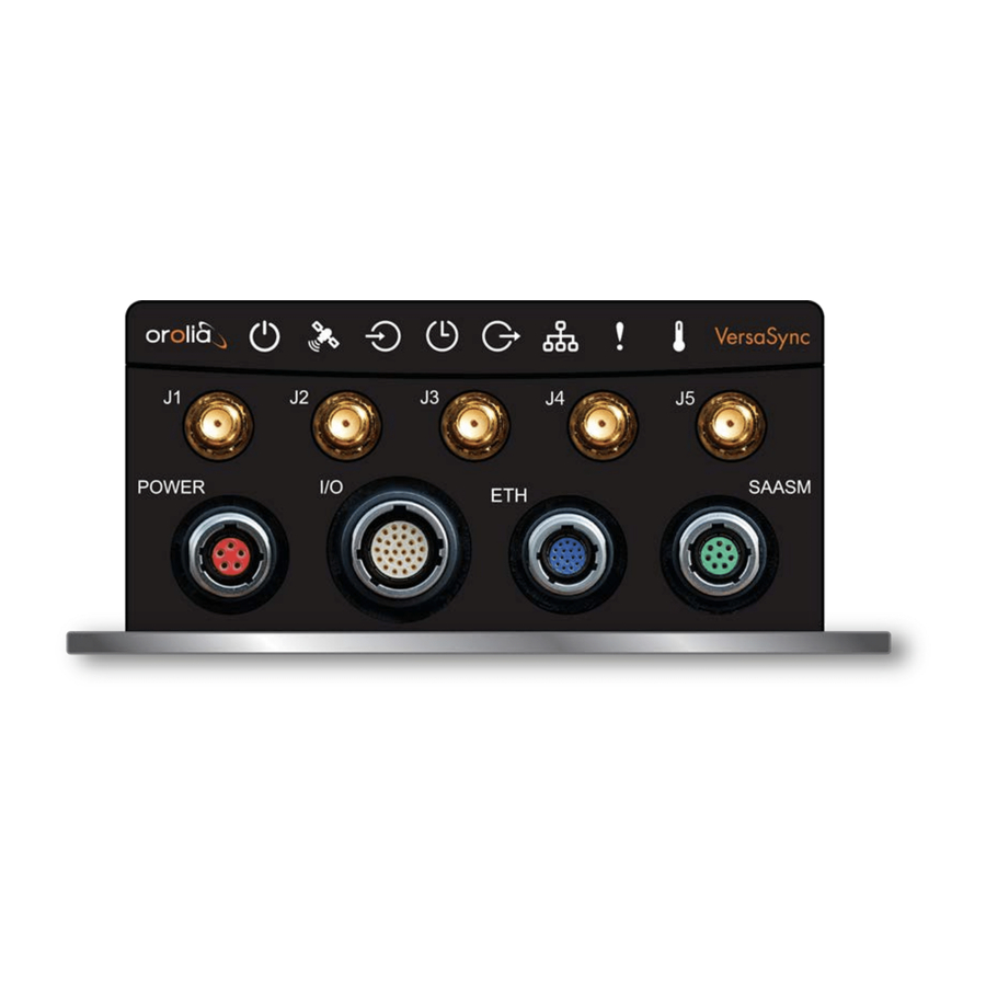
This section is designed to help you become familiar with the structure, features, and func- tions of the VersaSync. Interfaces Overview All of VersaSync's interfaces are integrated into the unit's connectors, which are located on the front panel: Figure 1-1:... -
Page 8: Input Timing Interfaces
10 MHz 1PPS ASCII/HaveQuick ASCII/NMEA NTP server, PTP v2 master Multi I/O interfaces (connector no. 4) are software-configurable, see "Assigning I/O Pins" on page 21. 1.1.3 Other Interfaces USB serial equivalent: CLI interface (Connector 4) VersaSync Getting Started Guide Rev. 8... -
Page 9: Connectors And Their Pinouts
1.2 Connectors and their Pinouts Connectors and their Pinouts All of VersaSync's connectors are provided at the front panel of the unit, below the Status LEDs. 1.2.1 Power Connector Note: View in mating direction from front. Table 1-3: Power connector pinout Signal (10 to 32 V) -
Page 10: Input/Output Connector
1.2.2 Input/Output Connector VersaSync has a 26- pin input/output connector that offers 8 software- configurable CHANNELS, plus one fixed DCLS channel, and a USB interface. To learn more about types of interfaces and signals, and how to configure them, see "Assigning I/O Pins"... -
Page 11: Ethernet Connector
Optional I/O Connector The Optional I/O connector is used in conjunction with the Option Board that is available for VersaSync. If the unit is not equipped with an Option Board, this connector is not used. VersaSync Getting Started Guide Rev. 8... -
Page 12: Coaxial Connectors
1.2 Connectors and their Pinouts 1.2.5 Coaxial Connectors VersaSync offers five (5) coaxial connectors, three (3) of which can be configured at the factory to accommodate requirements for e.g., additional 10 MHz outputs. The minimum configuration includes the GNSS antenna and a 10 MHz sinewave... -
Page 13: Included Cables
1.3 Included Cables Included Cables The VersaSync Evaluation Kit contains the following cables (antenna cable not shown): Power Cable I/O Cable VersaSync Getting Started Guide Rev. 8... - Page 14 1.3 Included Cables I/O Breakout Cable Ethernet Data Cable VersaSync Getting Started Guide Rev. 8...
-
Page 15: Status Leds
1.4 Status LEDs Status LEDs VersaSync's front panel status LEDs provide a real-time status overview: Eight (8) LEDs indicate the unit's current operating state: The LEDs can be disabled, see "Blackout Mode" on page 11. 1.4.1 Blinking Intervals The status LEDs can communicate five different operating states: "OFF"... -
Page 16: Legend, Individual Leds
Unit is in Holdover (valid) System Clock OK (valid) FAST Invalid Time (Holdover period exceeded, or oscillator damaged) No output signal(s) detected/all outputs are disabled FAST Malfunction detected (short circuit, or overload) Outputs are enabled VersaSync Getting Started Guide Rev. 8... -
Page 17: Blackout Mode
"0". The VersaSync Web UI VersaSync has an integrated web user interface (referred to as "Web UI" throughout this documentation) that can be accessed from a computer over a network connection, using a standard web browser. The Web UI is the most complete way to configure the unit, and for status monitoring during everyday operation. -
Page 18: The Web Ui Home Screen
1.5 The VersaSync Web UI 1.5.1 The Web UI HOME Screen HOME screen of the VersaSync web user interface ("Web UI") provides com- prehensive status information at a glance, including: vital system information current status of the references key performance/accuracy data major events. -
Page 19: Quick Start
These cables are included in the Evaluation kit. If you plan to use your own cables, some of these instructions may not apply. The step-by-step instructions below outline the VersaSync installation and configuration process: Install VersaSync... -
Page 20: Network Setup
("Web UI") is used to configure and monitor the unit. The Web UI is available through one of the Ethernet ports via a network connection. Default settings: VersaSync network settings default to static IP addresses. The Ethenet ports come pre- configured with IP addresses as follows: Eth0 - 192.168.1.1 Eth1 - 192.168.1.2... -
Page 21: Network Connection
2.1 Network Setup Default subnet mask: 255.255.255.0 Note: VersaSync supports zeroconf: If you have a DHCP-enabled network, you can use zeroconf for initial setup. For more information, see "Zero Con- figuration Setup" on page 19. Otherwise follow the instructions below for conventional setup. - Page 22 If you are on a DHCP-enabled network, you can assign an IP address by enabling DHCP on your unit . Use the dhcp4set <x> on command, (x being 0/1 for ETH0 and ETH1, respectively). VersaSync Getting Started Guide Rev. 8...
- Page 23 Or, follow the steps below to set an IP address through the Web UI. Log In to the Web UI a. On a PC connected to VersaSync via ETH0 or ETH1, start a web browser. b. Navigate to the IP address obtained or assigned in Step 2.
- Page 24 Click submit, and start a new Web UI session by entering the new IP address into your browser and logging in. e. You have now established a network connection with VersaSync. Continue with other configurations e.g., NTP settings, references, outputs, etc. See the manuals.spectracom.com...
-
Page 25: Zero Configuration Setup
(DHCP must be enabled through the Web UI or CLI) in circumstances when your unit is not connected directly to a PC when you wish to access the Web UI of your VersaSync without using the CLI com- mands or serial connection anytime the IP address of a unit is not known VersaSync Getting Started Guide Rev. -
Page 26: Using Zeroconf
If you do not have physical access to the unit, you can obtain the MAC 0 address by accessing VersaSync's CLI via the I/O connector USB port, using e.g., the ifconfig command. Once you logged into the VersaSync via zeroconf, you can retrieve the DHCP address for future use: Navigate to MANAGEMENT: NETWORK >... -
Page 27: Assigning I/O Pins
2.3 Assigning I/O Pins Assigning I/O Pins VersaSync's I/O connector is software configurable, i.e. the pin interfaces and the signal modulations can be configured by the user via the VersaSync Web UI. The software-configurable 26-pin I/O connector comprises 9 user-configurable Channels, plus one fixed USB interface. -
Page 28: Signal Types
DCLS outputs and three DCLS inputs are available for e.g., 1PPS, xPPS, IRIG, HaveQuick, ASCII ToD signal transmission. Single-ended Serial Lines VersaSync provides up to 3 RX and 3 TX RS232 interfaces for e.g., ASCII ToD – NMEA 0183 (ICD-GPS-153). - Page 29 = This Signal Message type cannot be assigned to this Channel = ASCII Time Code Configuring a new Input or Output 1. In the VersaSync Web UI, navigate to MANAGEMENT > NETWORK: Pin Layout. Pin Layout screen will be displayed.
- Page 30 Apply Changes. Restoring the Default I/O Configuration VersaSync is shipped with a default I/O configuration that you can be customized. However, if required you can restore the default configuration at any time after applying changes. The following illustration shows the...
- Page 31 To reload the currently used I/O configuration after adding pin layout changes, but before clicking Apply Changes: A. Navigate to the MANAGEMENT: NETWORK > Pin Layout screen. B. In the Actions panel on the left, click Reload Layout. VersaSync Getting Started Guide Rev. 8...
-
Page 32: Safety: Before You Begin Installation
Recycle the mentioned components at their end of life. Recycle Follow local laws. SAFETY: Before You Begin Installation DANGER! If the equipment is used in a manner not specified by the man- ufacturer, the protection provided by the equipment may be impaired. VersaSync Getting Started Guide Rev. 8... -
Page 33: Regulatory Compliance
MIL compliance Tested in accordance with MIL-STD-810G: MIL-STD 810G, 506.6 MIL-STD 810G, 509.6 MIL-STD 810G, 516.7 MIL-STD 810G, 514.7 VersaSync Getting Started Guide Rev. 8... -
Page 34: Fcc Compliance
Operation of this equipment in a residential area is likely to cause harmful interference in which case the user will be required to correct the interference at his/her own expense. Other compliance EN 60068-2-6 RoHS, WEEE compliant. VersaSync Getting Started Guide Rev. 8... -
Page 35: Technical Support
Configuration panel), and events log. Thank you for your cooperation. Regional Contact Orolia operates globally and has offices in several locations around the world. The Orolia (Spectracom) main offices are listed below: Table 4-1: Orolia contact information Country Location...
Need help?
Do you have a question about the VersaSync and is the answer not in the manual?
Questions and answers