Table of Contents
Advertisement
the benchmark for emc
M a n u a l
F o r
O p e r a t i o n
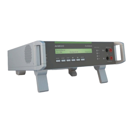
AutoWave
Portable solution to simulate and
measure Battery Supply Voltage
Variation
FM Version ≥ 5.09.00
The Automotive industry is facing the necessity to investigate
the behavior of the battery voltage variations and their effects to
electronic components connected to the supply network of the
cars, testing emission and immunity.
The
two
major
international
procedures to simulate different phenomena's related to the
battery supply lines are ISO 16750-2 for 12V and 24V supply
voltages and ISO 21848-2 for 42V supply voltage.
Version: 5.9.1/ 29.02.2016
Replaces: 5.9.0/ 03.02.2016
Filename:
UserManual-AutoWave-E-V5.9.1.doc
Printdate: 29.02.16
standards
describing
ISO 7637-2
ISO 16750-2
ISO 21848-2
SAE J1113
Manufacturer spec as
test
per GM, Ford, Chrysler,
Mercedes, BMW, VW,
PSA, Renault, Fiat ......
Advertisement
Table of Contents

Related Manuals for EM TEST AutoWave


Summary of Contents for EM TEST AutoWave
- Page 1 M a n u a l F o r O p e r a t i o n AutoWave Portable solution to simulate and measure Battery Supply Voltage Variation FM Version ≥ 5.09.00 ISO 7637-2 The Automotive industry is facing the necessity to investigate ...
- Page 2 Switzerland Phone : +41 61 717 91 91 Fax : +41 61 717 91 99 URL : http://www.emtest.com Copyright © 2016 EM TEST Switzerland GmbH All right reserved. Specifications subject to change Manual for Operation V 5.9.1 2 / 45...
- Page 3 Should you have any questions or find any errors, please contact your EM Test representative or send an email to EM Test. Copying or reproducing all or any part of the contents of this manual without the permission of EM Test is strictly prohibited.
-
Page 4: Table Of Contents
Calibration and Verification ....................... 37 6.2.1. Factory calibration ..........................37 6.2.2. Guideline to determine the calibration period of EM Test instrumentation ........37 6.2.3. Calibration of Accessories made by passive components only: ............37 6.2.4. Periodically In-house verification ...................... 37 6.3. -
Page 5: Model Overview
EM TEST AutoWave Model Overview 1.1. AutoWave Model and extension modules Basic model Module includes WaveGenerator - On-Board Supply Simulator with Dual Channel outputs for dc source control. - WaveControl software to generate wave shapes based on segments, point to point matrix. -
Page 6: Put In Service Functions
EM TEST AutoWave Put in service Functions 2.1. Front view LED Power Cursor "" "" LED Running Setup LED Trigger LED display output channels 1...4 Mode 10 LED display input channels 1...2 Start 11 Input channel 1 & 2 ( option ) - Page 7 EM TEST AutoWave 6. Cursor key "" "" Cursor Key with the following functions - Scrolling in the menus - Setting the values up / down 7. Setup Menu button for the device configuration menu. See Chapter 3.2.2. Setup Menu 8.
-
Page 8: Rear View
CH 4 : Auxiliary channel for Ford specs. 2. Framebus IN / OUT Daisy Chain bus with Sub D 15 poles male and female connectors. This port is used as communication and control bus between EM Test devices. Manual for Operation V 5.9.1 8 / 45... - Page 9 EM TEST AutoWave 3. CAN port CAN port 9 pole Sub D female connector Pin assignment 1: nc 2: CAN_L The Philips PCA82C251 CAN transceiver for 24V 3: CAN GND system serves as the interface between the CAN 4: nc protocol controller and the physical bus.
- Page 10 EM TEST AutoWave 9. Mains input The plug is part of the mains filter. ( 90 - 250V / 1A ) 10. Trigger IN Trigger input for event triggering. This trigger inputs are connected directly to the DSP signal processor.
- Page 11 EM TEST AutoWave 11. Trigger OUT Trigger outputs for event triggering. This trigger outputs are generated from the DSP signal processor. Max. voltage: 24V ( pull up ) Current : 100mA : For use the trigger out the user has...
- Page 12 The test will start and does not stop if the monitor signal is at low level during the wave start Settings The DUT monitor is settable in the AutoWave software and has the following function Disabled no function Stop...
-
Page 13: Put In Service
2.3.2. Installation in a System The AutoWave is used to control one or more DC sources and / or for measuring and recording of the transient behavior of a voltage during a sequence. 2.3.2.1. Installation or mount in a 19” Rack 1. -
Page 14: Hardware Wiring
There are two solutions to connect the computer to the AutoWave. - IEEE connection - Ethernet connection Both interface connections are applicable. Depends of the implementation EM Test propose the IEEE or Ethernet interface. iso.control software uses the IEEE interface. Ethernet interface is not supported by iso.control. - Page 15 EM TEST AutoWave 2.3.3.1. Wiring Devices Wiring Setup example with: AutoWave UCS 200 VDS 200N LD200 Manual for Operation V 5.9.1 15 / 45...
- Page 16 Supply connections from VDS200 to UCS200 and PFS200 can be wired inside the rack. Note : Do never connect The PFS200 output 0-10V in parallel with any AutoWave output. In this case the controlled DC source will deliver a wrong output signal. It is not allowed to connect two output sources in parallel.
- Page 17 EM TEST AutoWave Setup 3: example with: This configuration is suitable for testing Ford AC CI-230 tests with four waves at the Rack 1 same time. The figure shows the output for: RDS 200 RDS 200 - General tests at UCS output...
- Page 18 EM TEST AutoWave Setup 4: example with: Rack MPG 200 LD 200 PFS200 VDS 200N EFT 200 CNA 200 AutoWave for replace ARB 2714 Manual for Operation V 5.9.1 18 / 45...
- Page 19 EM TEST AutoWave 2.3.3.2. Wiring examples with AMP 200 Setup 5: example with: Rack LD 200N AMP 200N AutoWave UCS 200N VDS 200N Manual for Operation V 5.9.1 19 / 45...
- Page 20 EM TEST AutoWave Setup 7: example with: Rack 1 RDS 200 RDS 200 RDS 200 AMP 200N AutoWave PFS 200N VDS 200N Rack 2 LD 200N UCS 200N Setup 8: example with: Rack 1 RDS 200 RDS 200 AMP 200N...
- Page 21 EM TEST AutoWave 2.3.3.3. Setup with PFM 200N100 Setup 11: example with: Rack AutoWave PFM 200N100 VDS 200N Manual for Operation V 5.9.1 21 / 45...
- Page 22 EM TEST AutoWave 2.3.3.4. Setup with AutoWave and VDS 200Q and PFM 200N100 Setup 12: example with: Rack AutoWave PFM 200N100 VDS 200Q 25, Q 50 External : AMP 200 Manual for Operation V 5.9.1 22 / 45...
- Page 23 EM TEST AutoWave 2.3.3.5. Setup with AutoWave and VDS 200Q and PFM 200N100 Setup 13: example with: Rack AutoWave VDS 200Q100 External : PFM 200N100 Manual for Operation V 5.9.1 23 / 45...
-
Page 24: Operation
Power on After switching on, AutoWave needs approx. 35s for booting. During this time the display is blank. AutoWave is ready when the display shows AutoWave and the current version. The AutoWave is operated by an easy menu control system. Five function keys are available to select parameters and functions. - Page 25 The output active LED indicates the output channel(s) of the selected file. Note : Files with multiple waves indicates all used output channels. The software AutoWave delivers the detailed information about the wave on each channel. status blinking : Running...
- Page 26 EM TEST AutoWave Start, Break and Restart same file Start, Stop and return to WaveGenerator menu Manual for Operation V 5.9.1 26 / 45...
- Page 27 EM TEST AutoWave 3.2.1.2. Menu Wave Recorder Functions Recording the voltage variation in the lab setup. Replay of the measured data via an adequate dc source or amplifier. Check of the DUT under real world conditions. Channel selection Recording Manual for Operation V 5.9.1...
- Page 28 EM TEST AutoWave 3.2.1.3. Menu Wave Manager Functions - Copy file to USB Memory stick - Load file from USB Memory stick - Delete file Function selection Select a file and - Delete - Copy - Load Manual for Operation V 5.9.1...
-
Page 29: Setup Menu
AutoWave 3.2.2. Setup Menu In the setup menu all settings of the AutoWave can be done manually. The following figures show the configuration of the different parameters. How to navigate in the Setup menu Figure 4.2 shows the handling of the Setup menu. The small buttons inside the circle shows how to step through the menu or parameter list. -
Page 30: Dc Source
3.2.3. DC Source Parameter to control the connected voltage source. This setting must be done for each channel CH1...CH4 with a connected voltage source. AutoWave calculates automatically the correct output signal for controlling the source. Channel Selected output channel for setting the parameters... -
Page 31: Sample Frequency (Only With The Option Record)
EM TEST AutoWave 3.2.4. Sample frequency (only with the option record) Sample frequency for data recording. The max. sampling frequency is limited by the number of used measuring channels. Sampling frequency Default 5kS/s Sampling Frequency [kHz] depends on the number of channels... -
Page 32: Dut Monitor
- Notify: Message will be written on a file - Stop: Wave stops and continue according the user decision 3.2.8. GPIB Address GPIB Address for using the AutoWave with the software iso.control Standard : IEEE 488 Address : 1...30 Default : Default address for iso.control software... -
Page 33: Date
EM TEST AutoWave 3.2.12. Date Day : 1...31 Month : 1...12 Year : 2000...2200 Note: When pressing Setup to exit the Date setup, the display returns after few seconds delay to the Configuration display 3.2.13. Time The time is used for mark the stored files. -
Page 34: Test Equipment
AC input The AC mains power input is a wide range AC input that allows to operate the AutoWave in every country of the world. With the voltage input range from 90V ... 250V and 47Hz ... 63Hz it is not necessary to use an adapter transformer. -
Page 35: Technical Data
Unlimited Segments per wave form 20-30 depends on the complexity of the segment WaveRecorder Number of input channels 2 channels (ExtBoard for AutoWave required) Input voltage ranges 5V, 10V, 20V, 50V and 100V; unipolar or bipolar Resolution 16 Bit Accuracy better than 0.2%... - Page 36 EM TEST AutoWave Display and Controls Display Text LCD 2 lines, 40 characters LED indicators Power On Active channel 6 (2 inputs, 4 outputs) Trigger Running status Operation 6 function keys Trigger and DUT Monitoring Trigger 2 inputs, 2 outputs...
-
Page 37: Maintenance
EM TEST equipment. EM TEST doesn’t know each customer’s Quality Assurance Policy nor do we know how often the equipment is used and what kind of tests are performed during the life cycle of a test equipment. Only the customer knows all the details and therefore the customer needs to specify the calibration interval for his test equipment. -
Page 38: Calibration
EM TEST AutoWave 6.3. Calibration For periodical calibration the AutoWave has to return back to the manufacturer 6.4. Verification A verification can be done with the following procedure: Output channel Setting a defined voltage to the output channel and verification with a DMM ( 5½ digit ) Measuring: 0.00V... -
Page 39: Useful Accessories
D-Link : DUB-E100 For communication with the AutoWave via Ethernet a Hi-Speed USB 2.0 Fast Ethernet Adapter type DUB-E100 is available. This connection is used if the AutoWave is not installed in a rack with other EM Test equipment. Product Features: •... -
Page 40: Annex
1. Press the OK button to enter the Device update window. B : When the user has different firmware versions to operate with the AutoWave. 1. Press the Update button in the device setup for enter the Device update window. - Page 41 A bar graph shows the booting progress. After a successful update the actual firmware of the AutoWave is displayed in the field “Actual Firmware Version”. 4. Press the OK button to return to the Device Setup Window.
-
Page 42: Basic Waves
8.2. Basic Waves The AutoWave generates the waves like an arbitrary generator as PointWaves, where all samples are stored in a file. As an advantage the AutoWave firmware generates the waves as segmented waves from a parameter list. This has the advantage to save a lot of memory and to create waves who can not be realized by PointWaves. - Page 43 EM TEST AutoWave Profile Square Ramp Manual for Operation V 5.9.1 43 / 45...
-
Page 44: Declaration Of Ce-Conformity
EM TEST AutoWave 8.3. Declaration of CE-Conformity Manufacturer : EM TEST Switzerland GmbH Address: Sternenhofstr. 15 CH 4153 Reinach Switzerland declares, that under is sole responsibility, the product’s listed below, including all their options, are conformity with the applicable CE directives listed below using the relevant section of the following EC standards and other normative documents. -
Page 45: Autowave - General Diagram
EM TEST AutoWave 8.4. AutoWave - General Diagram Manual for Operation V 5.9.1 45 / 45...
Need help?
Do you have a question about the AutoWave and is the answer not in the manual?
Questions and answers