
Related Manuals for PI 9359-1


Summary of Contents for PI 9359-1
- Page 1 PG-USB user manual (english) Art.Nr. 9359-1 Art.Nr. 9359-1.05M 14.05.2019 © PI 2019...
-
Page 2: Table Of Contents
Content 1 Description ............................3 1.1 Basic circuit diagram ........................3 2 System requirements ........................3 2.1 Operating system(s) ........................3 2.2 Software ............................3 2.3 Hardware ...........................3 3 Installation ............................3 3.1 Hardware ...........................3 3.1.1 Extension set PG-USB ......................4 3.2 Software ............................4 3.2.1 Driver for Windows XP .....................4 3.2.2 Driver for Windows 98 ......................4 3.2.3 Uninstallation of the USB driver and installation of a new version .........6 3.2.4 Installation of the Step5 ©... -
Page 3: Description
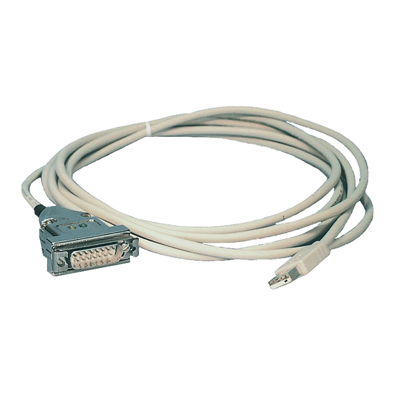
1 Description The PG-USB is an active cable for the connection of a Siemens X4/X5 interface to the PC USB port. The cable does not need any supply from the controller because it is completely supplied from the connected PC. This supply is also be used so that the cable is active towards the controller. 1.1 Basic circuit diagram 2 System requirements 2.1 Operating system(s) -
Page 4: Extension Set Pg-Usb
3.1.1 Extension set PG-USB The PG-USB is active toward his control. An extension is sufficient, in which the following pins are placed 1:1: 2-2 / 6-6 / 7-7 / 9-9. Solder on the shield of cables at both ends on the metal case of the Sub-D plug connector. - Page 5 3) Test the connection optionally with the S5 controller with a Windows program (eg: PG2000 from this CD) 4.) Then start the SETUP.EXE file on the installation CD for "S5VCOM for Win98" 5.) Select the installation path and click "Next" 6.) Select designation and location for the start menu and click on "Next"...
-
Page 6: Uninstallation Of The Usb Driver And Installation Of A New Version
COM1 [03F8h,IRQ4] COM1 COM2 [02F8h,IRQ3] COM2 COM1 [03F8h,IRQ4] COM1,COM2 COM3 [03E8h,IRQ4] COM1,COM3 COM2 [02F8h,IRQ3] COM2,COM3 COM1 [03F8h,IRQ4] COM1,COM2,COM3 COM4 [02E8h,IRQ3] Under the area "Program" the virtual COM port can be closed, the language of the program can be changed or the program can be minimized as tray icon. 3.2.3 Uninstallation of the USB driver and installation of a new version Download the uninstallation tool from the homepage. - Page 7 4.In the next dialog, start the installation by clicking on the "Install" button. The installation wizard will now copy the required data. Please wait a moment. 5. Specify the folder where the software S5 is installed. Please wait while the installation routine searches for the S5 software version.
-
Page 8: Control Elements
4 Control elements 4.1 Status-LEDs Green LED Off:: No data transmission Green LED flashes: Computer receives data from the PLC Yellow LED Off: No data transmission Yellow LED flashes: Computer sends data to the PLC 5 Implementing Connect your module as described in the chapter " Hardware installation " to the PLC and to the programming device or to your computer. - Page 9 2. Choose from menu "View" => "S5 155U-90 ..." In the menu “Options“ click “Interfaces“. 3. A dialog appears. In the section “Interface“ you can configure the “PLC – Interface“ (COM – Port). 4. Set in the section "Bus grip" the tick "Grip allways only one block from PLC", "FB- names", "Bst.
-
Page 10: Simatic Step© 5 Manager
5.1.2 SIMATIC Step© 5 Manager 1. Start your SIMATIC Step© 5 Manager by using the desktop link or the application entry in the start menu. 2. in the "File" menu , in submenu "project" you can the "Setting" dialog open. 3. - Page 11 4. OK“ leads you to a new dialog. Type in the „Project Name“ and the „Subfolder“ of the „Project Path“ With „Create“ the chosen configuration is confirmed. If you want to use one of the other options, please read this further in the manual of the WinCC software.
-
Page 12: Windows Control Center Flexible 2004 (Wincc Flexibel) (V5.2.0.0)
It is important that the chosen driver fits with the PLC otherwise the connection cannot be established. 8. In the explorer you should see into the variable manager the branch "SIMATIC S5 PROGRAMMERS PORT". Expand the branch and the protocols for several connections will appear Right click on the desired connection „S5- AS511“. - Page 13 options. Important for the connection are: => the communication driver (set up which PLC you are using (eg: „SIMATIC S5 AS511“) => select the used "CPU - type" (eg "S5 95U") => configure the interface parameters in the section "terminal" (eg: baud rate „9600“, Parity„even“, Data bits „8“, Stop bits „1“).
-
Page 14: Protool/Pro V6.0 Sp2
9. Press the button „Transfer“ to start communication with the terminal. Your project is about to be transferred. The communication with the operator terminal is so successfully established . 5.1.5 ProTool/Pro v6.0 SP2 1. Start ProTool/Pro by using the desktop link or program entry in the start menu. 2. -
Page 15: S5 For Windows V5.02
7. confirm with „OK“ until you got back to the „PLC Selection“.Go on with „Next“. 8. In the main window start the Transfer Settings dialog by clicking on „File“ „Transfer“ „Settings...“. Coose„Seriall“ and the COM interface of the operating terminal (e.g.: „COM1“). set the baud rate to "19200". - Page 16 1. Start the “S5 for Windows” software by using the link on your desktop or use the link in your start menu (standard is “Programs\S5 for Windows\S5 for Windows“) 2. Choose File - >Preferences... (top left in the menu bar) to configure the communication configuration between the computer and the PLC.
- Page 17 5. In this dialog you can see all PLC´s which are connected to your PC. Choose from the list box (left) the desired station (the PLC) and confirm with "OK". (In the example "2") 6. Close the preferences dialog by pressing the „OK“...
-
Page 18: Technical Data
6 Technical data Supply voltage: 5V DC Power consumption: 0,3 watt Display: 2 status-LEDs for RXT/TXD to the PLC: TTY/20mA current loop (PG-USB aktiv, PLC passiv) Interfaces: to the PD/PC: USB 1.1 cable type A Operating temperature: 0 - 55°C Case: metal case Dimensions:... -
Page 19: Troubleshooting
not used not used not used not used not used 7 Troubleshooting 7.1 Troubleshooting When trying to run the installation appears an error message that this software is not executable under the operating system XP/NT/2000. The S5VCOM driver is ONLY required for Windows 95/98/Me. The other operating systems like Windows XP/2000 have integrated this driver in the operating system and do not need it. - Page 20 In the first 4 * 2 bytes in the system stands the COM ports are known: F8 03 COM1 F8 02 COM2 E8 03 COM3 E8 02 COM4 00 00 Empty entry (here not available) In our case there is simply no more free COM port. When an empty entry is present, then cant be used only the required for this IRQ.
- Page 21 The corresponding dialog is displayed. In this is also the version of the driver. Right click over the image. It appears additional control elements where you click ONLY on the button VCOMLOG! Confirm with "OK". In the installation directory of S5VCOM was generated the file "VCOM.LOG".
Need help?
Do you have a question about the 9359-1 and is the answer not in the manual?
Questions and answers