
Related Manuals for PI MPI-II Series


Summary of Contents for PI MPI-II Series
- Page 1 MPI-II user manual (english) Art.Nr. 9352 Art.Nr. 9352.05M Art.Nr. 9352.10M Art.Nr. 9352.15M 14.05.2019 © PI 2019...
-
Page 2: Table Of Contents
Content 1 Description ............................4 2 System requirements ........................4 2.1 Operating system(s) ........................4 2.2 Software ............................4 2.3 Hardware ...........................4 2.4 Provided PLCs ..........................4 3 Installation ............................5 3.1 Hardware ...........................5 3.2 Software ............................6 3.3 USB-driver-installation for 32-bit-systems ................6 3.4 USB-driver-installation for Win7 64-bit .................10 4 Control elements ..........................15 4.1 Keys ............................15 4.2 Display ............................16... - Page 3 7.5 Parameterize TELEService .....................51 7.5.1 Index "Network": ......................51 7.5.2 Index "Modem": ......................52 7.5.3 Index "Serial parameter": ....................54 7.5.4 Index "Access Protection": .....................54 7.5.5 Index "GSM/ISDN/SMS": ....................55 7.5.6 Index "Internet/Mail": .....................61 7.6 Tuning .............................62 7.7 Factory defaults ........................63 7.8 PPI Boot off ..........................63 7.9 Emergency-Loader ........................64 8 MPI cable manager .........................64 8.1 Description ..........................64...
-
Page 4: Description
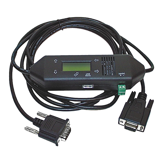
1 Description The MPI-II-Cable connects the programming device or PC over the serial Interface (COM-Port) or the PC over the USB-Bus with the MPI- or DP/FMS-Connector of the S7-300/400 PLC. The Cable selects automatically on the first access which Port and which Baud rate is used. With our PLC- Programming-Application PG-95/PG-2000 or S7-for-Windows works the MPI-II-Cable with up to 115.2kBaud on the PC - Side. -
Page 5: Installation
• S7-400 (provides baudrates up to 12M) • FM-devices • Sinamix (Step7-direct-driver up V1.20 or PLCVCom up V2.71) • MicroMaster and other electrical drives and inverter-feds (Step7-direct-driver up V1.20 or PLCVCom up V2.71) • Sinumerik (only PLC-side) • SEW-EURODRIVE power inverter •... -
Page 6: Software
(no gender-changer or so) Interfacecable 9pin to Modem Order.No. 9350-TS The adapter for the TS-function only works with the MPI-II Cable with the order-number 9352 ! MPI-II as HMI-Adapter (HMI = Human Machine Interface): The HMI-possibility allows the connection of a operator panel (who has not an internal MPI-port, but the HMI-protocol and a RS232-interface or USB) with a S7-300/400. -
Page 7: Usb-Driver-Installation For 32-Bit-Systems
3.3 USB-driver-installation for 32-bit-systems The S7-Interface S7-USB, MPI-USB or MPI-II-Kabel over USB as well as the devices of TeleService-familiy will be connected to USB 1.1-compatible port of the PC. This opens the Hardware-Installation-Wizard: We don´t need a connection to Windows update. Select now "Install from a list or specific location": Page 7 of 92 Handbook MPI-II... - Page 8 Enter as source the folder "..\USB-Treiber-x86". Either in the folder where the downloaded drivers were extracted or the directory on the product CD: The message of windows logo test skip with "Continue Anyway": Handbook MPI-II Page 8 of 92...
- Page 9 After copying the data appears a little moment later the success message: Upon a successful installation the "PI_Usb.Sys driver" will be displayed without any warnings in the device manager: Page 9 of 92 Handbook MPI-II...
- Page 10 Will this entry in the device manager shown with a "yellow exclamation mark", then please install the driver again or look in the driver properties about the reason. If the driver has to be updated, please use the function "Update ..." in the driver properties: If the driver has to be deleted, please use the function "Uninstall"...
-
Page 11: Usb-Driver-Installation For Win7 64-Bit
3.4 USB-driver-installation for Win7 64-bit The S7-Interface S7-USB, MPI-USB or MPI-II-Kabel over USB as well as the devices of TeleService-familiy will be connected to USB 1.1-compatible port of the PC. After the first plug of the device Win7 displays the message Nach dem ersten Anstecken am PC meldet Win7 zuerst „Installing device driver software“... - Page 12 With a right mouse-button-click you will open the properties of the new device: Handbook MPI-II Page 12 of 92...
- Page 13 Now select "Update Driver...": Page 13 of 92 Handbook MPI-II...
- Page 14 Please select "Browse my computer for driver software" and define as source the folder "..\USB- Treiber-x64". Either in the folder where the downloaded drivers were extracted or the directory on the product CD: After pressing "Next" the message appears of windows UAC Please press install and a little moment later appears the success message Handbook MPI-II Page 14 of 92...
- Page 15 To verify the successful installation, you can look again in the device manager: Here may appear no exclamation mark! If the driver has to be updated, please use the function "Update driver ..." in the driver properties: Page 15 of 92 Handbook MPI-II...
- Page 16 If the driver has to be deleted, please use the function "Uninstall" and set the check-box in "Delete the driver software for this device": If you install older versions of PLCVCom, Step7-direct-driver or S7IFC, the actual usb- driver will be possible overwritten by previous versions because it was included until 01/11/2012 in their install-shields! Handbook MPI-II Page 16 of 92...
-
Page 17: Control Elements
4 Control elements 4.1 Keys Name Description ENTER Change menu and confirm input. LEFT Go one menu level back. Cancel input (Input will not be saved). RIGHT Select sub menu. Navigate upwards. Enhancement a value. DOWN Navigate downwards. Depreciation a value. 4.2 Display First line #02PD00¯... - Page 18 Baud rate recognition and access way active. 115,2k or baud rate recognition is active. (cable is configured as TS – adapter) 19,2k 19,2k (cable is configured as TS – adapter) 38,4k 38,4k (cable is configured as TS – adapter) 57,6k 57,6k (cable is configured as TS –...
-
Page 19: Implementing
With the following baud rate settings, the menu message changes accordingly: Baud rate – configuration 1. line 2. line PPI 9,6k – (PPISER96) PPISER96 ACTIVE PPI 19,2k – (PPISER19) PPISER19 ACTIVE PPI 187,5k – (PPIMulti) ???PM? ???? PPILAN – (PPILAN) PPILAN ACTIVE PPIUSB –... -
Page 20: Using The Plc-Vcom
Config Go back to the “Config” menu and navigate down to the “PG/PC” menu. PG/PC Pressenter. PG/PC Press Enter to configure the "Baudrate". Baudrate PG-Baud Search for the entry “from PC” and confirm with enter from PC The cable is now ready to work.. Go back to the menu "message" to see the status. 5.2 Using the PLC-VCOM (The PLC-VCOM is only needed if your module is not connected via the 9 pin COM port to the computer. - Page 21 menu. 2. Choose from "View" => "S7-300/400" In the menu “Options“ click “Interfaces“.. 3. A dialog appears, in which you are able to set the “AG-Interface” (COM-port) in the section “Interfaces”. 4. Configure the baud rate in the section “Bus access“...
-
Page 22: Pset Pg/Pc Interface
The connection between PG 2000 and the PLC is now established. A new window appears. Now you can edit the blocks in the PLC. 5.3.2 PSet PG/PC interface This step is required for the following software: => TIA-Portal => SIMATIC Step© 7 Manager =>... -
Page 23: Tcp/Ip Rfc1006 Communication
TIC ETH/USB.PPI.1 or some “TCP/IP” entries If this is the case, please continue with the step MPI settings or Profibus settings. If so not please install the "TIC-driver" on this PC and after a restart this entries must exist. If you want to install the TCP/IP-driver follow the link. - Page 24 8. Open the properties dialog 9. Is the device-type is not identical with your used device, search for your device with "Search Device". Select the device in the result windows and click on the button "Apply". 10. Activate the "Automatic-mode" when you will be shure, that the connected PLC sends cyclic bus- parameter-protocols.
-
Page 25: Profibus Setting
11. Save your configuration with „OK“ and close the „Set PG/PC–interface“ dialog with „OK“. 5.3.2.3 Profibus setting 12. Mark the entry „TIC ETH/USB(PROFIBUS)“ and click on „Properties“. 13. Open the properties dialog 14. Is the device-type is not identical with your used device, search for your device with "Search Device". -
Page 26: Tcp/Ip Rfc1006 Setting
15. Activate the "Automatic-mode" when you will be shure, that the connected PLC sends cyclic bus- parameter-protocols. When not please configure the bus by hand. 16. Save your configuration with „OK“ and close the „Set PG/PC–interface“ dialog with „OK“. 5.3.2.4 TCP/IP RFC1006 setting 17. -
Page 27: Protool/Pro Runtime (Rt) Configuration
5.3.2.5 ProTool/Pro RunTime (RT) Configuration 18. If you want to use ProTool/Pro RunTime you can set the "PG/PC Interface" by selecting the entry "DPSONLINE". Therefore you have to select "Access Point of Application" and configure it as described above. The easiest way is to use the S7-LAN/MPI-LAN/MPI- USB- driver which supports USB and LAN products. -
Page 28: Windows Control Center (Wincc) (V6.0)
assembly with his blocks. 5.3.4 Windows Control Center (WinCC) (v6.0) Configurate the interface as described in Set PD/PC-Interface. 1. Start WinCC by using the desktop link or the program entry in the start menu. 2. Choose „New” in the menu „File” or click on the white („letter”) symbol to start a new project. 3. - Page 29 6. For a proper working communication with the PLC there must be defined how the software has to communicate with the PLC Therefore you have to right-click on “Tag Management” it opens the context menu. Choose “New Driver Connection … “. 7.
-
Page 30: Mpi Configuration
5.3.4.1 MPI Configuration 9. Now you are able to type in the name of the connection. With a click on “Configuration“ a new dialog will appear. Now you are able to set the properties of the connection. Set up the station address of the PLC (in this example "2“). - Page 31 10. A dialog appears where you can configure the connection parameters. Set up the IP - Address of the module and configure the rack number as well as the slot number. Confirm this configuration by clicking “OK”. Example configuration: IP - address 192.168.1.55 Rack - Number: 0 Slot - Nr.: 2 11.
-
Page 32: Communication And Fault Diagnosis
Format adaptation: „WordToUnsignedWord“ Click on „Choose” beside the Address to define the address from the variable. Example configuration: The data area from the variable is set to „Mark“ and the address is set to „Word”. The edit box „MW“ is set to „0”. 14. -
Page 33: Windows Control Center Flexible 2004 (Wincc Flexible) (V5.2.0.0)
21. If you take a right-click on the error value a window opens with “Help”. Click on the “Help” window and a yellow window appears (tooltip) with detailed error descriptions. 22. Lets see what happens if the connection runs properly. Start the connection from your WinCC Explorer. - Page 34 In the context menu click on “Add Connection“. 5. A new configuration window “Connections” opens in the right part of the main window. This offers you different setting options. Important for the connection is: => the communication driver (set up which PLC you are using (example: "SIMATIC S7 300/400“)) =>...
-
Page 35: Protool/Pro V6.0 Sp2
9. Press the button „Transfer“ to start communication with the terminal. Your project is about to be transferred. The WinCC flexible software is now able to communicate with your operator panel. 5.3.6 ProTool/Pro v6.0 SP2 Please be sure that the interface configuration is correct as described in PD/PC-set interface 1. - Page 36 configuration. In the sector „Net parameter“ choose the interface which uses your module on the PLC (e.g. „MPI“). Configure the baud rate to „187.5“. 6. The button „More ...“ leads you to a small dialog where the „Highest Station Address“ should be configured to „126“.
-
Page 37: Microwin V3.2 (Only For S7 200)
5.3.7 Microwin v3.2 (only for S7 200) Please be sure that the interface configuration is correct as described in PD/PC-set interface 1. Start Microwin using the desktop link or program entry in the Start menu. 2. Click on „Type“ in the menu „PLC Configure the „PLC Type“... -
Page 38: Microwin V4.0 In Ppi-Multimaster-Mode
the communication with the PLC. 5. The sector „Address“ should be updated and displays the „PLC Type”. Also the CPU of the PLC is displayed in the right part of the dialog. 6. Confirm with „OK“ until you get back to the main window. The communication with the PLC ist now established. - Page 39 5. Start your Microwin-Software. 6. Click on the button „Set PG/PC-Interface“ under „View“ in the left down part of the window. 7. Select the entry „PC/PPI cable(PPI)“ and click on the button „Properties“. 8. In the menu „PPI“ you are able to configure diverse settings like for e.g.
-
Page 40: S7 For Windows V5.02
12. When the PLC was found, the picture changes it like this: 13. Prove the dialog with „OK“ until you would be in the main window. The communication to the PLC is now ready. 5.3.9 S7 for Windows v5.02 Handbook MPI-II Page 40 of 92... - Page 41 1. Start the „S7 for Windows” software by using the link on your desktop or use the link in your start menu (standard is „Programs\S7 for Windows\S7 for Windows“) 2. Choose File - >Preferences... to configure the communication configuration between the computer and the PLC.
-
Page 42: Configure Operating Terminal Via Mpi-Ii / Mpi-Usb
4. After the software is configured , please click „Select PLC” in the area „MPI Converter“. A new dialog appears where you can select the desired PLC 5. The dialog displays all the PLCs that can be found in your MPI bus. Select the desired one and confirm with „OK”. -
Page 43: Direct Setting Of A Slave Address To A Passive Profibus-Slave
MENU Navigate with the Up/Down – Keys until you reach the Menu “Config”. Config Press Enter. Config Search for the submenu „Mode“. Press Enter Mode Mode Press the Enter key to configure the new mode. SOND USB Config Navigate in the Config menu to "PG / PC". Press the Enter key. PD/PC PD/PC Press Enter to configure the "baudrate"... -
Page 44: Configuration
is only master". There is no another note in this case, you will use this function as if you are connected with your PD to the module. 6 Configuration 6.1 Keys and Display The menu message is explained in the chapter "Control elements"... -
Page 45: Config
Config PD/PC PD interface settings Config MPI-BUS MPI interface settings Config USBCurrent Change the current of the cable Config Data Un-/locks configuration send by the computer 6.1.2 Config o Mode o Password o Reset o Default settings o Language o Protocol o PD/PC o MPI-BUS o USBCurrent... - Page 46 PPI-communication (MultiMaster 9K6 - 187,5K) over RS232- or USB- PPIMulti interface (with PLCVCom) HINT: „MPI SER“, „SOND SER“, „PPI 19K2“ and „PPI 9K6“ doesn't fit with the MPI-USB cable (Ord. No. 9352 USB). • Password: Choose this menu to change the configuration password. (Standard: „0“) •...
- Page 47 - Master - lokalNo - HSA - Baudrate Change the speed of the MPI - Bus. Available baud rates: „Auto“, „19,2k“, „45,45k“, „93,75k“, „187,5k“, „500k“, „1,5M“, „3M“, „6M“, „12M“ HINT: The baud rates„3M“, „6M“ and „12M“ can only be configured by cable. These higher baud rates (from “3M“) will be overwritten by the PC.
-
Page 48: Bus
• Data Change to „Lock“ if you want that configuration data coming of the computer will be ignored (only important if you are using „3M“ or higher baud rates The maximum baud rate of the PC driver is used if you „Unlock“ this option. 6.1.3 Bus Select the menu „Bus“... -
Page 49: User Interface
7.1 Language selection: Select the menu Configuration to change the language permanently: 7.2 User interface: Select near Search which interfaces are searched permanently for devices. You could choose: • Serial All existing COM-Ports are scanned for devices • USB Search devices which are connected by USB •... - Page 50 The background of the lines could use the following colours: • White The OS of the device is up-to-date • Light blue The OS of the device is not up-to-date, the device could be updated • Red An error occured by accessing the device •...
-
Page 51: Bus Configuration
The button Exit leaves the application. 7.3 Bus configuration To parameterize the connection to the device, select a device and click "Parameterize". Regarding to the device you maybe have to click on the button Bus configuration (see parameterize table). Here you can parameterize the following: •... -
Page 52: Network Settings
(the less you use, the more performanceon the MPI-bus, must be corresponding with the configuration in the CPU’s) The TS-Adapter is the one and only master in the MPI- • PD/PC is the only master on the bus (adapter hast to speak to all passive clients) •... -
Page 53: Parameterize Teleservice
• DHCP-client not set active • IP Address 192.168.1.56 • Subnetmask 255.255.255.0 • Gateway address 0.0.0.0 • Device name empty 7.5 Parameterize TELEService To parameterize the device, first click on the device, after that on "Parameterize". Regarding to the device, you maybe have to click on the TELEService button. After clicking on "TELEService"... -
Page 54: Index "Modem
Station related: • PD/PC is the only master The TS-Adapter is the only master on the MPI-bus on the bus (adapter must speak to all passive clients) Which local station-address is used for the TS-Adapter. Please consider that a programming device has normally the number 0, •... - Page 55 Modem Settings: start command &F use factory settings echo off volume of speaker is low • Initialization speaker is on at connection output of the return values return values plain text &C1 DCD shows status of the carrier sound S0=1 automatic connection after 1 ring Switch to command mode •...
-
Page 56: Index "Serial Parameter
• Wait for dial tone In case the modem should wait for a free line, you should set the before dialing corresponding checkbox. • Number of redial At number of retries you could configure the number of retries for a attempts connection before the call is stopped. -
Page 57: Index "Gsm/Isdn/Sms
Access Protection: • The administrator can change the configuration over a telephone line. • The two user accounts can not change the configuration. • The username is maximal 8 characters long. • Every user and the administrator should use a password which is used to login in the TELEService over a telephone-line. - Page 58 • Type You could choose the location of the modem. ISDN Modem: Choose the type of the ISDN network: • AT&T 5ESS • Nothern Telecom DMS-100 • Type • EuroISDN NET3 (Standard) • INS64 • US NI-1 • VN4 • Protocol Choose the transfer protocol type: •...
- Page 59 • CLEAR • Multiple Subscriber Number is used for all ISDN channels. • MSN • If empty no MSN is used. GSM Modem: • PIN number of the SIM card, up to eight numeric characters (only for • PIN TELE-SERVICE GSM). •...
- Page 60 provider found • registration denied: Registration in the GSM-network is denied • Search network: In Search for a GSM-Provider • GSM: Attached to GSM • GSM(ROAMING): Attached to GSM, but with a Roaming-Partner. This could lead to high costs! • The radio quality is displayed, together with the bit-error-rate. Value Description: •...
- Page 61 Switches: • NO • SEND SMS • RECEIVE SMS • SEND+RECEIVE SMS • DMTF CONFIRMATION • SEND SMS+DTMF CONFIRMATION • RECEIVE SMS+DTMF CONFIRMATION • SEND+RECEIVE+DTMF CONFIRMATION • SEND MAIL • SMS • SEND MAIL+SEND SMS • SEND MAIL+RECEIVE SMS • SEND MAIL+SEND+RECEIVE SMS •...
- Page 62 The possible error conditions for the modem, mpi bus problems or other problems are displayed in this text-field. First the modem-related information is shown: Message • Modem ready • Modem error • No answer from modem • Modem detects ring •...
- Page 63 (FC=YYh) ErrCode 02: At state-protocol the Source-Address is detected as 127. This is the Broadcast-address which is not possible. ErrCode 03: The received State protocols destination address (XXX respectively YYY) does not exist in the MPI-Bus. (FC=ZZh) ErrCode 04: The function-code (YYh) of the received State protocol from XXX is incorrect. The 7th Bit is High, but according to the specification the Bit has to be low.
-
Page 64: Index "Internet/Mail
7.5.6 Index "Internet/Mail": The internet connection is configured by PPP, often a username and password is needed. Define them in "Internet access over PPP". Attention: This is NOT the username and password of your E-Mail-account! In the next section "Mail" the E-Mail-account is defined: Internet access over PPP: •... - Page 65 The following configuration is possible, it will be transferred to the Cable by pressing the button „OK“. The configuration is saved permanently in the Flash-ROM: At ProTool RT the communication could break down, because the • Delay before send MPI-Cable is transferring the answer-protocol to fast. In this case you could insert a time in 0.1ms ticks.
-
Page 66: Factory Defaults
Deactivates temporary the "S5 on MPI" function, the cable doesn't poll the bus anymore. send reset to cable: Send reset to cable. Console: Shows some information about the status of the connection. 7.7 Factory defaults This button sets the configuration of the selected device to factory defaults. 7.8 PPI Boot off In PPI boot mode S7IFC cannot communicate with the cable. -
Page 67: Mpi Cable Manager
After a click on Emergency-Loader the following dialog appears: On a click on Yes the emergency-loader tries to run the main program of the firmware. On a click on No the emergency-loader tries to rewrite the complete firmware. 8 MPI cable manager 8.1 Description The MPI cable manager allows you to install an update in your cables and modules and configure them. -
Page 68: Overview
3. Select in this dialog the program folder for the MPI cable manager startup items. Then click "Continue". 4. Wait for the installation of the files. 5. End the installation after a successful copy of data with "Finish". 8.3 Overview 8.3.1 Language After starting the application the tab Language is displayed at first: Handbook MPI-II... -
Page 69: Interface
In this Dialog you could choose the used language in the application. You could choose between German and English and confirm by clicking on the desired language. 8.3.2 Interface In „set interface“ you can choose the COM-port you device is connected at. Only the COM-port which was aktive at starting the MPI-Kabel-Manager are shown. -
Page 70: Update
8.3.3 Update The diskette show the current operating system installed on your PC for corresponding product. The cabel-symbol on the right show the operating system which is installed on your product at the moment. With the button „default settings“ you can set your products on default settings. Should the device be out of order after configurated. -
Page 71: Telephone Book
8.3.4.1 Telephone book At the moment not implemented! In this dialog you could define new elements or edit/erase existing elements in your telephone- book. You could edit the following data: => Name for the connection (these are displayed at connection) =>... -
Page 72: Extra
8.3.4.3 Extra In this dialog, all configuration to the TS-adapter is done. The actual state of the MPI-cable is displayed right of the button “TS-function”, where the follwing 4 possible Messages could apear: „TS-Adapterfunction is NOT activ. To activate press TS-function“ The MPI-cable acts like an PC-Adapter. -
Page 73: Ts-Function
8.3.4.3.2 „TS-function“ With this button you select the function of the MPI-cable as TS- or PC-adapter. Right of this button the actual state of the MPI-cable is displayed. 8.3.4.3.3 „configure adapter“ In the following dialog you could, after activating the MPI-cable as TS-adapter, configure the TS- spezific setup. - Page 74 Here you can configurate following: The TS-Adapter is the one and only master in the MPI-bus Which local station-address is used for the TS-Adapter. Please consider that a programming device has normally the number 0, operator panel have 1, PLC’s use 2, FM/CP’s 3 etc. Please: Never use the same station-number for 2 different stations! network related: Here you can configurate following:...
- Page 75 Ther are 2 possible calling technics: MFV tone, the telphone-number is transfer by several frequencies IWV pulse, the telephone-number is transfered with the count of several pulses on the line When you must a pre-call to establish a call outside your company, you could define it at Amtskennzahl.
- Page 76 The Access over a telephone-line on the PLC could be configured in this dialog. The Administrator could change the configuration over a telephone line, where an 2 User could not change the configuration. The User-Name is maximal 8 Chars long.Every user and the administrator could use a password which is used to log into the PLC over a telephone-line.
- Page 77 You could choose the Location of the Modem. ISDN modem: Type: Choose the type of the ISDN-network switch: AT&T 5ESS Nothern Telecom DMS-100 EuroISDN NET3 (Standard) INS64 US NI-1 Protocol: Choose the transfer-protocol-type: Modem like V.120 X.75 (Standard) Page 77 of 92 Handbook MPI-II...
- Page 78 ML-PPP SoftBonding HDLC CLEAR DN/MSN: Directory Number resp. Multiple Subscriber Number Is used for both ISDN-channels. When using the number 255 no DN/MSN is used. GSM modem: PIN: PIN-Number of the SIM-Card, up to 8 numeric chars, (only for TELE-SERVICE GSM). Provider: With the button „Provider“...
- Page 79 The Receive Quality is displayed, also as value together with the bit-error-rate. Value Description: 99 No network, no receive 00 Very, very bad receive-quality 01 Very bad receive-quality 02 to 09 Bad receive-quality 10 to 17 Medium receive-quality 18 to 25 Normal receive-quality 26 to 30 Good receive-quality 31 Best receive-quality Messages:...
- Page 80 The selected MPI/Profibus-Baudrate is wrong Overflow in internal LAN-Writebuffer LAN-Recieve-Error LAN-Send-Error The PD-Numberr is wrong The transferred SAP is wrong/unknown ErrCode 01: The Destination address (XXX) of a State protocol > 127 detected. In the MPI/Profibus-Bus there are no stations possible which station number is greater than 127. (FC=YYh) ErrCode 02: At state-protocol the Source-Address is detected as 127.
-
Page 81: Import Parameter
ErrCode 1E: FPGA has caused an interrupt although no data present. (SD1=XXh,SD1=YYh,CPU=ZZZ,FC=UUh) ErrCode 20: Unknown protocol at PPIMultimaster-Mode. (FC=XXh,Länge=YYY) ErrCode 21: Unknown baud-rate at PPIMultimaster-Mode. (Baudrate=XXh) After that additional hints are displayed. SMS: SMS: Switches Processing OFF / Only Receive / Only Send / Receive and Send. Attention: before setting ON check configuration, after activating the device will go into the MPI- BUS and tries to connect to the defined PLC. -
Page 82: Tuning
8.3.5 Tuning This tab is only used in some special cases. If you press the button „Check Adapter“ the cable is connected und after that the following dialog is displayed: There are the following configuration possible, they will be transferred to the MPI-Cable by pressing the button „Transfer“. -
Page 83: Plc-Vcom
HMI-Cable-Version: Some Touch-panels have the problem, that when they get a wrong version-information they never retry to connect (and then the correct version is transferred). In this case the HMI-version- information could be transferred immediately. A20-Terminal: When using the A20 or M20-Terminal, the control-lines on the serial port are not used. In that case the tele-service-function is not working. -
Page 84: Installation
9.2 Installation 1. Download the PLCVCom from the product-page of your MPI-product and start the installation. 2. After choosing language the welcome dialog appears in the chosen language. Click “Next“ to define the installation path (see right picture). This can be done with a click “Browse…” If you are ready press “Next“... -
Page 85: Final Configuration Of The Plc-Vcom
7. After the driver has been installed, please disconnect your MPI-USB Cable and than connect it again. This loads the new installed driver. “OK” to go on. 9.2.2 Final configuration of the PLC-VCOM 8. Choosing the COM – Port Already occupied COM port can be viewed in Windows Device Manager if you are not sure which COM ports are still available. -
Page 86: Overview
11. The “hardware assistent“ wants you to install the “USB < - > Serial“ driver. Click on “Next” to configure the driver search. 12. Choose in the next dialog “Search for the best device driver (recommended)“ and click on „Next“.. 13. -
Page 87: Status Description
9.3.1 Status description: PLC – VCom is connected with your cable/module and operational. PLC – VCom is not connected. The red symbol indicates that sending/receiving data has been failed. Receive status: (right field): Send status: (left field): Data is received from the Data is send to the cable/module if this one is cable/module if this one is... -
Page 88: Configuration Window
=> Lenguage: Switch the Language to english/german. => Help: opens the Help menu of the PLC-VCOM, when they should have problems or questions => “Minimize” the dialog. This button does not close the program. It just minimizes the program. You will find the PLC – VCom symbol in the Windows – taskbar beside the watch. 9.3.3 Configuration window 1. -
Page 89: Configuration
=> Ends the PLC-VCOM configuration and discards the entered / selected settings 9.4 Configuration 1. Start the PLC – VCom application, if this is not already running. 2. Open the PLC-VCOM by clicking on the icon PLC-VCOM in the system tray. 3. -
Page 90: Technical Data
Informationen zu den Optionen, die mit Hilfe der Checkboxen an und abgewählt werden können, erhalten Sie im Kapitel „Übersicht“ des PLC-VCOMs. 4. Bestätigen Sie Ihre Eingaben/Auswahl mit „OK“. 5. Im Hauptfenster des PLC-VCOMs erscheint nach einem erfolgreichen Verbindungsaufbau, der Kabeltype mit dem sich der Computer verbindet und der Verbindungsstatus „verbunden“. 6. -
Page 91: Pin Assignment Rs232
P24V 24V Supply input Ltg_A Data line A BiDi RTS-PG Request to Send to the PLC Note The shield is attached with the MPI/PPI connector via the shield of the adapter casing. To find directly attended PLC´s , RTS-AS and M5V must be connected in the cable. P5V means a output of the cable and works only as an output for a bus-termination with resistors. - Page 92 Important: Please do not lengthen this side, this side also supports the 5V/DC power supply (max. cable length are 5 meters) A longer cable would decrease the quality of the signal on the bus and may cause several errors in the transmission! Handbook MPI-II Page 92 of 92...
Need help?
Do you have a question about the MPI-II Series and is the answer not in the manual?
Questions and answers