
Subscribe to Our Youtube Channel
Related Manuals for TENDO Sprint System


Summary of Contents for TENDO Sprint System
- Page 1 TENDO Sprint System INTELLIGENT, WIRELESS TIMING SYSTEM Hardware User Manual www.tendosport.com...
-
Page 2: Table Of Contents
CONTENT QUICK START GUIDE………………………………………………………………………………………3 1 ACKNOWLEDGEMENT…………………………………………………………………………………3 2 SAFETY PRECAUTIONS……………………………………………………………………………… 3 3 PRODUCT DESCRIPTION……………………………………………………………………………. 4 3.1 About the product……………………………………………………………………………..4 3.2 Content of the basic TSS kit…………………………………………………………………5 3.3 Technical specifications………………………………………………………………………6 4 HARDWARE SETUP…………………………………………………………………………………….6 4.1 Battery installation…………………………………………………………………………….6 4.2 Photocell/reflector installation……………………………………………………………….6 4.3 Tripod installation……………………………………………………………………………..7 4.4 Photocell……………………………………………………………………………………….8 4.4.1 Photocell setup via menu panel………………………………………………….9 4.4.1.1 Switching ON………………….…………………………………………9... -
Page 3: Quick Start Guide
4. Start using TSS 1 ACKNOWLEDGEMENT Thank you for purchasing Tendo product. We hope you will be satisfied with our product and customer service. Please read the user manual fully before using the product. Save the manual for future reference. -
Page 4: Product Description
3 PRODUCT DESCRIPTION 3.1 About the product TENDO Sprint System (TSS) is a wireless computer system used to measure time of short distances in training and testing of athletes. Information provided by TSS is essential in sports where the performance is assessed thought speed, sprint, endurance, reaction, shuttle tests, etc. -
Page 5: Content Of The Basic Tss Kit
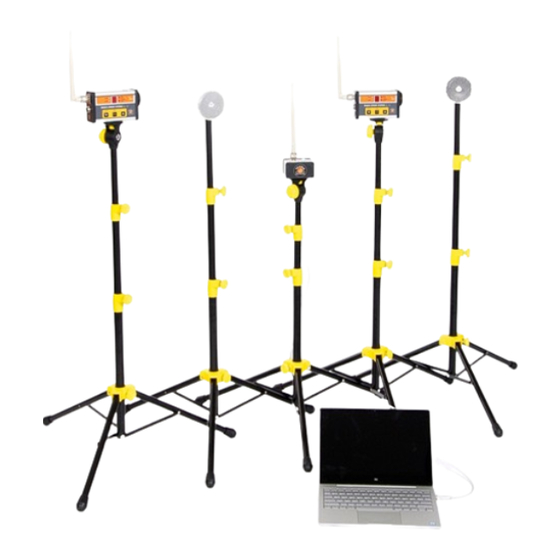
3.2 Content of the basic TSS kit 2 photocells 2 reflectors 1 TSS signal receiver 5 tripods 1 manual 1 computer software installation CD 1 carrier bag 2 sets of rechargeable batteries (4 pieces each set) 2 power adapters (10) 3 antennas (11) 1 signal receiver to PC connecting cable... -
Page 6: Technical Specifications
The kit can be expanded by purchasing more photocells and reflector pairs with tripods. Please contact your seller for more information 3.3 Technical specifications • Maximum distance between photocell and reflector is 5 m • Maximum distance between optogate and TSS signal receiver is 100 m •... -
Page 7: Tripod Installation
4.3 Tripod installation 1. Open the tripod so the bottom yellow plastic part is approximately 10 cm from the bottom end of the tube (see the picture below). Secure the position by tightening the locking screw. 2. Screw antenna onto the top connector of the photocell (see page 8). Attach the photocell to a steel plate located on the top of the tripod via a magnet. -
Page 8: Photocell
4.4 Photocell Menu panel Battery compartment There are three connectors located on the left side of the photocell: Antenna connector RFID reader connector for RFID chips Power adapter connector Optical sensor and speaker are located on the right side of the photocell. Fastening magnet is placed on the bottom of the photocell. -
Page 9: Photocell Setup Via Menu Panel
Immediately after the ON/OFF button is released, information about a current setting of the photocell is shown on a LED display for 5 seconds. 4.4.1.2 Photocell’s settings • The setting of the photocell represents the photocell’s function: = start 1 - 8 = split times = finish •... -
Page 10: Switching Off
CHANNEL MODE - choose from 0 to 3 (see page 6) RF MODE - E - Europe, A = USA 4.4.1.4 Switching OFF Press ON/OFF button (button of the left - downwards arrow) for 2 < seconds. After the long press (press and hold 2s <), you will hear a double beep and LED_power will turn off. -
Page 11: Battery Charging
4.4.3 Battery charging Each photocell has its own built-in battery charger. To charge the batteries use the power adapter which is part of the basic TSS set kit. Power adapter parameters: Input voltage: 110 - 230 V AC, 50 - 60 Hz Output voltage: 12 V DC, 1,2 A Only use rechargeable batteries: type NiMH, 2000 - 2500 mSh Plug the power adapter into a 230V AC power outlet... - Page 12 A multicolour LED light is placed on the top of the signal receiver: 1.Photocell x signal receiver communication: Photocell signalled with GREEN light (Power LED light) Short flash - Photocell x receiver communication is active Long flash - Photocell x receiver communication is not responding 2.PC x signal receiver communication: Receiver signalled with...
Need help?
Do you have a question about the Sprint System and is the answer not in the manual?
Questions and answers