Table of Contents
Advertisement
Quick Links
DIGITAL PANEL METERS
programmable -10 000 / +100 000 points
ÉTUDES ET RÉALISATIONS
DIP 506
ÉLECTRONIQUES / INSTRUMENTATIONS / AUTOMATISME
Route de Brindas - Parc d'activité d'Arbora - N°2
69510 - Soucieu en Jarrest
Tél. 04 72 31 31 30 - Fax 04 72 31 31 31
Tel. Intern. 33 4 72 31 31 30 - Fax Intern. 33 4 72 31 31 31
User handbook
Valid for instruments with version 03.xx
http: //www.ardetem.com - e-mail: info@ardetem.com
ARDETEM
Soucieu en Jarrest - FRANCE
Advertisement
Table of Contents

Related Manuals for ARDETEM DIP 506


Summary of Contents for ARDETEM DIP 506
- Page 1 Tél. 04 72 31 31 30 - Fax 04 72 31 31 31 Tel. Intern. 33 4 72 31 31 30 - Fax Intern. 33 4 72 31 31 31 User handbook Valid for instruments with version 03.xx http: //www.ardetem.com - e-mail: info@ardetem.com ARDETEM Soucieu en Jarrest - FRANCE...
-
Page 2: Table Of Contents
Summary Summary 1 . INTRODUCTION APPLICATION EXAMPLES 2 . SPACE REQUIREMENTS ERROR MESSAGES 3 . CONNECTINGS GENERAL WARRANTY CONDITIONS 4 . PROGRAMMING LEXIQUE 4.1 Communicating with the instrument 10. MODBUS ANNEXE 4.2 Oritentation through the programming 4.3 Main menu 4.4 Programming menu 4.4.1 Input programming 4.4.2 Display programming 4.5 Input features and programming limits... -
Page 3: Introduction
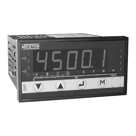
Decimal point moving, 1. INTRODUCTION Function tare, min. and Max. zero reset. The DIP506 is a high accuracy programmable panel meter, for gauge bridge inputs. It is equipped on its front face with a red display of five Bargraph: (display 16 leds) : B 14mm high digits, whose brighness suits applications in industrial control Allows fast evaluation of the measured value variations. -
Page 4: Space Requirements
2. SPACE REQUIREMENTS Case dimensions: (with terminals) 96 x 48 x 124 mm Fitting panel Max. thickness Terminals external case seal tightenings Panel mounting Cut out 44 x 91 mm Protection: Front face: IP 65 Case: IP20 Terminals: IP 20 Case: Self-extinguishing casing in black UL 94 V0 ABS. -
Page 5: Programming
4. PROGRAMMING 4.1 Communicating with the instrument Functions Alarms Location of terminals Led 5 Led 1 (view of case rear side) OUTPUTS Measure dis- Led 2 (options) play Led 6 Led 3 ACTIVE CURRENT VOLTAGE Led 7 Led 4 PASSIVE CURRENT From the measuring, several funtions are available simply by pressing 1 key, or 2 simultaneously. -
Page 6: Oritentation Through The Programming
Entering of a parameter: vertical 4.3 Main menu scrolling of First start by increasing or decreasing: 6888 The 1st digit and the sign: from -9 to +9. menus move 6588 The 2nd from 0 to 9. (relay / analog (analog Between each entering, confirm 6528 The 3rd from 0 to 9. - Page 8 4.4.2 Display programming ⇒ The instrument will Entering of the decimal automatically resume point location measure with the 04.00 previous configuration if no key is pressed dur- ing 1min. dO.diS The changing of this param- eter requires re-programming all parameters related to the relays and the analog ouptut, the bar- graph as well as all following dis- play parameters:...
- Page 9 Communication parameters slave number SLAvE entering of the slave number 0001 between 1 and 255 transmission speed bAUd function function function tare function decimal display min. and point hold Max. moving zero reset...
- Page 12 SAvE SAVE, YES Note: Exit from programming mode saving the configuration ( ) will automatically reset to zero the tare, min. and Max. as well as the recording of alarms. In case of modification of the decimal points location, the instrument will then SAVE YES offer after a all parameters related to the decimal point which have...
- Page 13 Choice of the operating mode: ModE.x 4.6.2 Digital output: - Data link RS485 (2 wires) • Mode setpoint - Protocoles format of data: integer and double integer MODBUS JBUS - Single transmission format 1 start bit Legend: 8 bits without parity coil supplied 1 stop bit OFF coil not supplied...
- Page 14 · On the relays: tiME.x • Time delay on the alarm No influence of error detections on the relay The relay time delay is adjustable from 000.0 to 025.0s. in 0.1s. increasesIt is active both on switching and switching back. Relay desactivated (coil not supplied) in case of error detection •...
- Page 15 br.bAr • Adjusting of the bargraph and Leds brightness • Response time: Lowest brightness Strongest brightness 1111 4444 The brightness level is visualised directly on Leds 5 and 8 and on the bargraph. Caution: during setting, the 4 Leds and the bargraph no longer represent intEG the measure, even in mode reading.
-
Page 16: Programming Menu
4.7 Configuration of the instrument Programming of the bridge excitation voltage • SEt.CF ALiM 5.000 . 5V 10.00 . 10V Programming of the auxiliary power supply frequency, in order FrE. to optimise the rejection of the parasite noise it may send Programming menu of the accesses to functions directly by disturbing the measure. - Page 17 Submenu 4.8 Reading of the configuration rEAd About Validation / Vertical move rEAd Validation / Vertical move Instrument type D506 instrument number Reading of the input parameters XXXXX InPut Reading of the measure display parameters 12345. A0123 diSPL X1 : - : No analog output Reading of the analog output parameters A : Analog output Out.MA...
- Page 18 4.10 New programming of the access code 4.11.2 Analog output simulation (mode generator) (accessible according to the programmed P .CodE access code and with option analog output) if code not valid GEnE. (old) Enter previ- display during 2s. ous code GEnE.
- Page 19 4.11.7 Display of the Max. value. t.MEnu (Accessible by in standard direct access) 4.11.4 Menu : Menu tare (Standard direct access by Accessible according to the programmed access code and if measure is not Pressing on allows visualising the min. recorded value shown in overstepping (display ...) alternating with message Revert to measure with...
- Page 20 5.3 Automatic setting (according to programmed access code see To obtain a better accuracy, it is then preferable to programme a lower Menu accessible by pressing keys caliber and go through the setting again. out.rA in mode measure. Message also appears during an electrical overstepping during the setting.
- Page 21 WARRANTY applying and duration The instrument is connected to the sensor with its plate. This instrument is garanteed by ARDETEM for a duration of 1 year Enter the automatic setting menu, validate d.in and adjust d.disp at 0 . against any design or manufacturing defects, under normal operating Load the plate, for example 500 kg.
-
Page 22: Input Programming
Analog output Input programming Out.MA Access to the voltage output programming sub-menu Access to the input programming sub-menu InPut Access to the current output programming sub-menu CALib Choice of the voltage caliber Out.U Analog output down scale Choice of the processing function Funct. - Page 23 LOGIC inputs t.Act.X Time delay position Access to the LOGIC inputs programming sub-menu Time delay on switching on alarm SIMPL Time delay on switching on alarm and off alarm tor 1 Programming of LOGIC input 1 doubL Programming of the relay associated Led Programming of LOGIC input 2 tor 2 LEdx...
- Page 24 Programming of the display Configuration of the instrument Access to the display characters programming sub-menu SEt.CF Access to the programming sub-menu Pr.diS Programming of the power supply frequency in order to FrE. Adjusting of digits brightness (4 levels) optimise the rejection of any parasite noise from br.diG supply on the measure.
- Page 25 • Displayed measure: ANNEXE: MODBUS The displayed measure value is taken without the decimal point. To read the 1 Table of Modbus addresses decimal point value, read the word at address 132. Format nb of words Address Address 132: Value of the analog output double integer bit 2 bit 1 bit 0 bit 15...
- Page 26 Measure = byte 3 x 256 3 + byte 4 x 256 2 + byte 1 x 256 + byte 2 Writing of 1 word: Function N°6: = 0 x 256 3 + 0 x 256 2 Request sequence: + 19 x 256 + 136 = 5000 Value of...
- Page 27 5 setting of the tare via the RS485: 4 CRC16 calculation algorythm: FFFF → CRC 2 codes are available: 5555: AUTO tare CRC ⊕ BYTE → CRC 6666: zero reset of the tare To activate these functions, simply write the code 5555 or 6666 to the address n = 0 code prog = 330 shifting by 1 bit to the...
Need help?
Do you have a question about the DIP 506 and is the answer not in the manual?
Questions and answers