Table of Contents
Advertisement
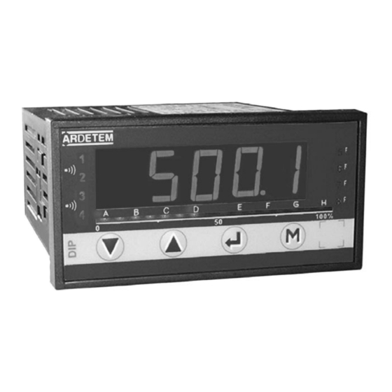
DIGITAL PANEL METER
programmable ±10 000 points
ÉTUDES ET RÉALISATIONS
DIP 10
ÉLECTRONIQUES / INSTRUMENTATIONS / AUTOMATISME
Route de Brindas - Parc d'activité d'Arbora - N°2
69510 - Soucieu en Jarrest
Tél. 04 72 31 31 30 - Fax 04 72 31 31 31
Tel. Intern. 33 4 72 31 31 30 - Fax Intern. 33 4 72 31 31 31
User handbook
Valid for instruments with version 01.xx
http: //www.ardetem.com - e-mail: info@ardetem.com
ARDETEM
Soucieu en Jarrest - FRANCE
Advertisement
Table of Contents

Related Manuals for ARDETEM DIP 10


Summary of Contents for ARDETEM DIP 10
- Page 1 Tél. 04 72 31 31 30 - Fax 04 72 31 31 31 Tel. Intern. 33 4 72 31 31 30 - Fax Intern. 33 4 72 31 31 31 User handbook Valid for instruments with version 01.xx http: //www.ardetem.com - e-mail: info@ardetem.com ARDETEM Soucieu en Jarrest - FRANCE...
-
Page 2: Table Of Contents
1 . INTRODUCTION 4.9 Programming of a new access code 4.10 - Functions of the the main menu 4.10.1 - Display simulation 2 . SPACE REQUIREMENTS 4.10.2 - Simulation of the analog output 3 . CONNECTINGS 4.10.3 - Menu CLEAr : Deleting of the recorded alarms 4 . -
Page 3: Introduction
1. INTRODUCTION Features of the inputs The DIP 10 is a high accuracy digital panel meter. It is equipped on front Types of Measure range adjustable Permanent Intrinsic Input INPUTS from overload error impedance face with a four 14 mm high red digits display, whose brightness suits applications in industrial control rooms perfectly. -
Page 4: Space Requirements
2. SPACE REQUIREMENTS Dimensions of the case: (with terminals) 96 x 48 x 124 mm Mounting panel max. thickness 30 terminals case external tightenings seal Mounting on panel cut out 44 x 91 mm Protection: Front face: IP 65 Housing: IP20 Terminals: IP 20 Housing: Self-extinguishing case of... -
Page 5: Connectings
3. CONNECTINGS 1 2 3 4 5 6 7 8 9 10 11 12 13 14 15 16 Location of the terminals (view of case rear face) INPUTS 2 RELAYS: TEMPERATURE PROCESS RESISTANCE AND POTENTIOMETER 0-440Ω resistance 300V Resistance >440Ω up to 2kΩ Pt100 3 wire (0-8kΩ... -
Page 6: Programming
4.2 Orientation through the programming 4. PROGRAMMING The dialogue is ensured by 4 keys located on the front face. 4.1 Communication with the instrument Several functions can be reached directly on the front panel Exit from a submenu to access next menu / access to the pro- Alarms gramming exit menu... -
Page 7: Programming Menu
4.4 Programming menu (according to options) Access to the programming of the input InPut Access to the programming of the display factor diSPL. Access to the programming of the analog output AnA. (option analog output) rELAY Access to the programming of the relays (option relay outputs) Access to the programming of the outputs, the relays SECU... -
Page 8: A / Process Signals P6
b. Temperature signals c. Resistive sensors temperature signals process signals process signals temperature inputs # Changing this parameter requires re-programming the following parameters related to the relays and the analog output: dISP SPxx, hystx, do.diS, Fo.diS If thermocouple tc-- tc-J tc-CA tc-S tc-r... - Page 9 4.4.2 Programming of the display factor...
- Page 10 rELAY rEL.1 AL.1 02.00 02.00 04.00 00.00 000.0...
-
Page 12: Features Of The Outputs And Programming Limits
Display of the meter: volume output (mA) Empty tank volume d.diSP = 0.000 in m 3 Full tank volume F.diSP =0.785 0.79 π Volume = L [ R² β/36 0 - C( R-h)/2 ] 0.75 0.67 0.59 Say a curve of 10 equally long segments: Measure range / nbr of segments = 20 mA/ 1 0 = 2 m A length of the 0.49 segment. -
Page 13: Relay Outputs
4.6.2 Relay outputs: • Mode setpoint led lit 2 relay outputs rEL.1 rEL.2 • Hysteresis independently programmable in the display unit. • Time delay independently programmable from 0 to 25 s, in 0.1s increments. SP.X SP.X • NO-NC contact 8 A - 250 V on resistive load - HYSx Activation or de-activation of alarm x AL.X... -
Page 14: Safeties
The information of sensor rupture can be reported: 4.6.3 Safeties: · On the relays No influence on the relay in case of sensor rupture diAG • Self-diagnosis: Relay de-activated (coil not supplied) in case of sensor The meter permanently watches any drifts which may occur on its com- rupture ponents. -
Page 15: Display Features
• Inhibition of the last digit (bottom weight) 4.6.4 Display features: L.dIG In the mode programming, the menu L.dIG allows suppressing the dis- play of the last digit, the latter being enforced to 0 if OFF is validated. Place of the decimal point for the inputs other than tempe- Point rature inputs •... -
Page 16: Access Code
4.9 Programming of a new access code Submenu About Validation / vertical move Enter former type of the instrument if code not valid dIP10 P .CodE XXXXX code (old) n ° if code correct number of the instrument 1 2 3 4 5. (old) display during 2s. -
Page 17: Simulation Of The Analog Output P16
4.10.2 Simulation of the analog output (mode generator) 4.10.4 Menu : Suppressing of the programmed tare CLr.tA (accessible according to the programmed (accessible according to the programmed access code and if option analog output) access code) the entered tare is not GEnE. -
Page 18: Functions Which Can Be Reached From
5.2 Functions which require pressing several keys: 5. FUNCTIONS WHICH CAN BE REACHED ON THE FRONT PANEL 5.2.1 Shifting of the display (accessible according to the programmed 5.1 Functions which require pressing only 1 key: access code) Shifting of the display down scale (AdJ.Lo) a / Display of the min. -
Page 19: Visualisation Of The Direct Measure
5.2.3 Visualisation and setting of the alarm setpoints note : only for temperature inputs : From the menu rEAd, the performed scale shiftings can be visualised in Option 2 or 4 relays the submenu InPut : Setting of the setpoints: There are 2 ways to adjust setpoints : offset slope and - either in mode programming entering the correct safety access code... -
Page 20: Error Messages P19
Inputs 6. ERROR MESSAGES InPut Access to the submenu programming of the input Upper or lower electrical Measure in overrange TYPE 2000 Type of input ---- overstepping of the input Voltage input Sensor rupture OPEn Displayable value overload. Current input Value set out of range Self-diagnosis error Err.1... - Page 21 Special linearisation Li.SPE CJ-t° Value of the external CJC Number of linearisation points NI100 input ni 100 Abscisse of a special linearisation point Type of degrees t° Ordinate of a special linearisation point °C Cut.oF Degree Celcius Cut-off programmable or not °F Degree Fahrenheit Display resolution for temperature inputs...
- Page 22 Relay outputs: x : 1 or 2 Safeties Access to the submenu programming of the relay outputs Access to the submenu programming of the safeties rELAY SECU Access to the programming of relay x rEL.x Programming of the sensor rupture safety ruPt.
- Page 23 Saving of the configuration Further functions Saving of the configuration Display of the minimum value InF. SAVE Saving No saving Display of the maximum value SuP. Awaiting transfer Deleting of the min. and max. UAit CLr.M Deleting of the recorded alarms CLEAr Reading of the instrument internal features Error messages...
Need help?
Do you have a question about the DIP 10 and is the answer not in the manual?
Questions and answers