Viessmann OpenTherm Operating Instructions Manual
Room temperature controller with digital time switch for vitodens 100-w, 111-w and 050-w
Hide thumbs
Also See for OpenTherm:

Related Manuals for Viessmann OpenTherm


Summary of Contents for Viessmann OpenTherm
- Page 1 VIESMANN Operating instructions for the system user OpenTherm room temperature controller with digital time switch For Vitodens 100-W, 111-W and 050-W Room temperature controller Please keep safe. 5837779 GB 12/2018...
- Page 2 Safety instructions For your safety Please follow these safety instructions closely to prevent accidents and material losses. Safety instructions explained Danger Note This symbol warns against the Details identified by the word "Note" risk of injury. contain additional information. Please note This symbol warns against the risk of material losses and envi- ronmental pollution.
- Page 3 Safety instructions For your safety (cont.) Working on the appliance ■ When adjusting settings and carrying ■ Never remove or change additional out work on the appliance always fol- parts or installed accessories. low the guidelines in these operating ■ Never open or retighten pipe connec- instructions.
- Page 4 Safety instructions For your safety (cont.) If you smell flue gas Danger Emergency contact Flue gas can lead to life threat- ening poisoning. If you smell gas or detect a gas leak ■ Shut down the heating sys- call the National Gas Emergency serv- tem.
- Page 5 Safety instructions For your safety (cont.) Installation room requirements Danger Please note Sealed vents result in a lack of Incorrect ambient conditions can combustion air. This leads to lead to heating system damage incomplete combustion and the and can put safe operation at formation of life threatening car- risk.
- Page 6 Safety instructions For your safety (cont.) Auxiliary components, spare and wearing parts Please note Only allow qualified contractors Components not tested with the to carry out installation or heating system may damage the replacement work. system or affect its function.
-
Page 7: Table Of Contents
Index Index Information Symbols........................ Intended use......................10 Introductory information Control unit function modes.................. 11 Where to find the controls Summary of controls and indicators..............12 ■ Controls and display elements................12 ■ Symbols on the display..................13 Commissioning Heating system operating mode................15 Time program or operating mode................. - Page 8 Index Index (cont.) Locking out controls (key lock)................29 ■ Temporarily interrupting or unlocking key lock..........29 Changing the display format of fault messages........... 29 Returning all settings to their delivered condition..........29 Checks Checking information.................... 30 What to do if... Rooms are too cold....................
-
Page 9: Information
Information Symbols Sym- Meaning Reference to other document containing further information Step in a diagram: The numbers correspond to the order in which the steps are carried out. Warning of material losses and environmental pollution Live electrical area Pay particular attention. ■... -
Page 10: Intended Use
Information Intended use The appliance is intended solely for Any usage beyond this must be installation and operation in sealed approved by the manufacturer in each unvented heating systems that comply individual case. with EN 12828, with due attention paid to the associated installation, service Incorrect usage or operation of the and operating instructions. -
Page 11: Introductory Information
Introductory information Control unit function modes Your heating contractor set the function Note mode during commissioning. DHW heating is active continuously or in accordance with the set switching Two function modes are possible: times, regardless of the function mode ■ Room temperature-dependent opera- set. -
Page 12: Where To Find The Controls
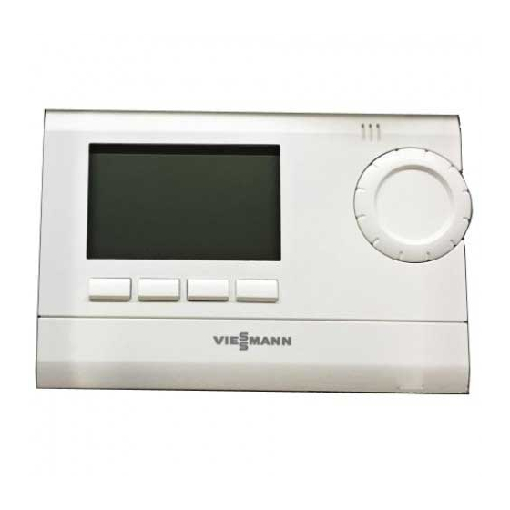
Where to find the controls Summary of controls and indicators Controls and display elements 08:26 ROOM TEMP ° 21 3 MODE PARTY ECO INFO A Display C Keys B Rotary selector for changing the D Reset (see page 32) temperature/value... -
Page 13: Symbols On The Display
Where to find the controls Summary of controls and indicators (cont.) Symbols on the display These symbols are not always dis- played, but appear subject to operating conditions. 08:26 ROOM TEMP ° 21 3 MODE PARTY INFO A Time F Function display B Text line G Keys C Temperature display... - Page 14 Where to find the controls Summary of controls and indicators (cont.) B +/-: Change value / : Scroll through menu C Confirm selection Save value Default display 08:26 ° C 21 3 When idle, the screen always shows Information on operation the room temperature, time and (sub- You can perform most setting and ject to settings) selected time phases...
-
Page 15: Commissioning
Commissioning Heating system operating mode Depending on the installation and set- tings, your heating system is either room temperature-dependent or weather-compensated in conjunction with an outside temperature sensor. ■ In room temperature-dependent mode, the set room temperature is controlled via the flow temperature. ■... -
Page 16: Time Program Or Operating Mode
Commissioning Time program or operating mode You can choose between 3 preset time ■ "COMFORT 3" programs (P1 to P3) or select a perma- ■ "REDUCED TEMP" nent operating mode. You can change ■ "FROST PROTECTION" the switching times of the time pro- grams individually. -
Page 17: Constant Operating Modes
Commissioning Time program or operating mode (cont.) Monday to Friday Time program P3 ■ 06:00 to 08:00 h and 16:00 to 22:00 h: Central heating in accordance with the Central heating with standard room following time program: temperature (Comfort 1) ■... -
Page 18: Changing The Selected Time Program And Set Temperatures
Commissioning Time program or operating mode (cont.) Changing the selected time program and set temperatures You can set the following days and 12. OK to confirm groups of days: ■ Entire week (1 to 7) 13. +/- for the required temperature ■... - Page 19 Commissioning Time program or operating mode (cont.) 09. NEW 07. Select the required program with Days flash. 10. +/- for the required group of days 08. OK to confirm or single day 09. Press NEXT to call up the set 11.
-
Page 20: Central Heating
Central heating Selecting the operating mode You can choose between the following ■ "PERM REDUCED" time programs and operating modes: Continuous reduced mode ■ "P 1" to "P 3" ■ "FROST PROTECTION" Alternating operation with standard Continuous frost protection mode and reduced room temperature according to the set switching times. -
Page 21: Reduced Mode
Central heating Temporarily changing the room temperature (cont.) Ending comfort mode early 2. Press OK to end comfort mode. 1. Press PARTY. "PARTY OFF" appears. Reduced mode In reduced mode, the room tempera- 3. Use the rotary selector to set the ture is regulated to a preselected set required increase or reduction of value (delivered condition: 17 °C). -
Page 22: Changing The Heating Curve For Weather-Compensated Operation
Central heating Permanently changing the room temperature (cont.) 7. Use +/- to change or press OK to 9. Change with +/- or press ESC to move to the next setting (e.g. exit programming. "COMFORT 1"). 8. OK to confirm The next setting appears. Changing the heating curve for weather-compensated opera- tion In weather-compensated operation, the... - Page 23 Central heating Permanently changing the room temperature (cont.) The line shows the curve for the stand- Shifting the heating curve means ard room temperature. The delivered reducing the flow temperature for condition is shown. reduced mode. The value of "SHIFT" The heating curve is changed with acts on both heating circuits.
-
Page 24: Changing The Room Temperature For A Few Days (Holiday Mode)
Central heating Permanently changing the room temperature (cont.) 08. Use 09. OK to confirm to select the required setting: 10. Use +/- or the rotary selector to ■ – "LOW END" for heating circuit change the setting. without mixer – "LOW END 2" for heating cir- 11. -
Page 25: Stopping Or Interrupting The Holiday Program
Central heating Changing the room temperature for a few days… (cont.) Stopping or interrupting the holiday program Stopping the holiday program 3. Select "SETTINGS" with 1. Press OFF. 4. OK to confirm "HOLIDAY OFF" appears. 5. Select "HOLIDAY" with 2. OK to confirm The holiday program is interrupted. -
Page 26: Dhw Heating
DHW heating Setting the time program and DHW temperature You can set time phases for DHW heat- 08. OK to confirm ing: ■ The DHW cylinder is heated during 09. NEW the set time phases when using a Days flash. boiler with a DHW cylinder connected to it. -
Page 27: Further Adjustments
Further adjustments Time and date Press the following keys: 6. OK to confirm 1. INFO 7. Press +/- to make the required set- ting. 2. MODE 8. OK to confirm and to move to the 3. Select "SETTINGS" with next setting. 9. -
Page 28: Setting The Language
Further adjustments Setting the language 1. Confirm "LANGUAGE" with OK. 3. OK to confirm 2. +/- for the required language Changing the default display 1. Confirm "DISPLAY" with OK. 2. +/- for the required display version Setting Display version 08:26 °... -
Page 29: Setting The Contrast
Further adjustments Setting the contrast You can change the display contrast in 2. Use +/- to set the required value (0 stages. to 15). 1. Confirm "CONTRAST" with OK. 3. OK to confirm Locking out controls (key lock) You can lock out the controls by switch- 3. -
Page 30: Checks
Checks Checking information You can check the following information ■ Actual flow temperature with INFO: ■ Date and time ■ Current outside temperature ■ Active time program Press INFO repeatedly until the ■ Fault messages required information appears. ■ Set flow temperature... -
Page 31: What To Do If
What to do if... Rooms are too cold Cause Remedy The room temperature controller is in- Check the settings and correct if re- correctly set. quired: ■ Program ■ Room temperature ■ Time Note For further causes, see the boiler oper- ating instructions Rooms are too hot Cause... -
Page 32: Carrying Out A Reset
What to do if... Carrying out a reset Press the reset button with a suitable instrument. -
Page 33: Maintenance
Maintenance Cleaning This device can be cleaned with a com- mercially available domestic cleaning agent. Never use any scouring agents. -
Page 34: Appendix
Appendix Menu structure in setting mode (MODE) MODE PERM COMFORT P1 ACTIVE PERM REDUCED ACTIVATE P2 FROST PROTECTION P2 ACTIVE SETTINGS ACTIVATE P3 Menu structure in settings SETTINGS HOLIDAY TARGET TEMP START HOLIDAY COMFORT 3 YEAR COMFORT 2 MONTH COMFORT 1 REDUCED TEMP HOUR FROST PROTECTION... - Page 35 Appendix Menu structure in settings (cont.) Note Menu point TSP-PARAMETER only appears if the room temperature con- troller acts on heating circuits (mixer extension kit).
-
Page 36: Keyword Index
Keyword index Keyword index Checks..........30 Operating mode......16, 20 Cleaning..........33 Operating mode, selecting....20 Contrast, setting.........29 Controls..........13 – Locking out........29 Reset..........32 Controls and display elements...12 Room temperature – Changing........20, 21 – Changing for a few days....24 Default display, changing....28 –... - Page 40 Contact your local contractor if you have any questions about your system or wish to arrange maintenance or repair work. You can find local contractors on the inter- net at www.viessmann.de. Viessmann Werke GmbH & Co. KG Viessmann Limited D-35107 Allendorf...
Need help?
Do you have a question about the OpenTherm and is the answer not in the manual?
Questions and answers