
Subscribe to Our Youtube Channel
Related Manuals for Penguin Computing Arctica 4806XP Series


Summary of Contents for Penguin Computing Arctica 4806XP Series
- Page 1 Arctica 4806xp switch Installation Guide Content Arctica 4806xp Series switch Installation Guide Version 1.1 2017-02-07...
-
Page 2: Table Of Contents
Arctica 4806xp switch Installation Guide Content Content 1. Introduction ....................1 1.1.Product Brief ......................1 1.1.1.Overview ......................... 1 1.1.2.Features and Benefits .................... 1 1.2.Description of Hardware ................... 3 1.2.1.Front Panel ......................3 1.2.2.Back Panel ......................4 1.3.Status LEDs ....................... 4 1.4.Port Description ...................... - Page 3 Arctica 4806xp switch Installation Guide Content 3.2.7.AC Power Supply Connection ................7 3.2.8.Earthing Cable Connection ................... 8 3.2.9.Checking the Switch ....................9...
-
Page 4: Introduction
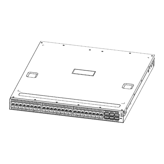
Arctica 4806xp switch Installation Guide Chapter 1 Introduction 1. Introduction 1.1.Product Brief 1.1.1.Overview Arctica 4806xp switch is the next generation of 10Gb Ethernet routing switches. Arc- tica 4806xp switch is based on 10Gb switching technology. It is particularly designed for 40Gb server of data center to fetch in the scene in high consistency. - Page 5 Arctica 4806xp switch Installation Guide Chapter 1 Introduction Arctica 4806xp switch provides 48 10Gb SFP+ and 6 40Gb QSFP+ ports. Each QSFP+ port can be split into 4 10Gb SFP+ ports. ◇ Support 10Gb Ethernet 10Gb Ethernet which adopts full-duplex technology instead of low-speed, half-duplex CSMA/CD protocol, is a big leap in the evolution of Ethernet.
-
Page 6: Description Of Hardware
Arctica 4806xp switch Installation Guide Chapter 1 Introduction WEB interface and RMON. It can mail the correlative sensitive information to the admin- istrator abide by SMTP protocol. Arctica 4806xp supports SSH protocol, ensure the con- figuration management security of the switch. It is adopted the web management system ‘LinkManager’... -
Page 7: Back Panel
Arctica 4806xp switch Installation Guide Chapter 1 Introduction 1, the parity bit as none, the default baud rate as 115200bps. 1.2.2.Back Panel The back panel of Arctica 4806xp includes 2 alternating current of 220V power mod- ule (it provides redundancy backups), 4 fan rabbets and 1 rear panel card Table 1-2 The descriptions of rear panel card 10/100/1000Base-T USB2.0 inter-... - Page 8 Arctica 4806xp switch Installation Guide Chapter 1 Introduction No power supply or make a mis- Put out take. Green light The system is power on and System status ways on running normally. START indicate LED Put out The system is power off. Table 1-4 The explanation of indicator light of rear panel Indicator light Rear panel sign...
-
Page 9: Port Description
Arctica 4806xp switch Installation Guide Chapter 1 Introduction Green light The port is under the connection state of 40G. always on Amber light The port is under the connection state of 4x10G. always on Indicator light of QSFP+ port Wink The port is transmitting data. -
Page 10: Power Supply Module
Arctica 4806xp switch Installation Guide Chapter 1 Introduction Table 1-7 Cables supported by Arctica 4806xp Type Manufacturer Model Standard 40G QSFP+ Cable Tyco 2053638-3 30AWG, 3.0m QSFP+ to 4Xsfp+ Cable Amphenol 582410007 30AWG, 3.0m 747571051 30AWG, 0.5m Molex QSFP to QSFP Cable 747571101 30AWG, 1.0m 747571301... -
Page 11: 550W Power Module
Arctica 4806xp switch Installation Guide Chapter 1 Introduction of the power supply. The power supply module supports the hot plug. 1.5.2.550W Power Module Arctica 4806xp switch also can have two 550W power modules in standard configu- ration, it provides redundancy backups. It only provides airflow front to back mode. The maximum power is 550W, the import is 100VAC~240VAC and the export is 12V +/- 5%. -
Page 12: System Specifications
Arctica 4806xp switch Installation Guide Chapter 1 Introduction Different airflow fan modules can not be mix used. Power modules’ airflow must be same with fan modules’. 1.7.System Specifications Table 1-8 System Specifications of Arctica 4806xp Type Arctica 4806xp Attribute Dimension(W * H * D) (mm) 433.8 * 44 * 550 Weight 10.133 kg... -
Page 13: Installation Notice
Arctica 4806xp switch Installation Guide Chapter 2 Installation Notice 2. Installation Notice To ensure the proper operation of Arctica 4806xp and your physical security, please read carefully the following installation guide. 2.1.Environmental Requirements ■ The switch must be installed in a clean area. Otherwise, the switch may be damaged by electrostatic adherence. -
Page 14: Temperature And Humidity
Arctica 4806xp switch Installation Guide Chapter 2 Installation Notice the threshold value. Average (mg/m³) Max (mg/m³) 0.006 0.03 0.04 0.15 0.05 0.15 0.01 Table 2-2 Environmental Requirements: Particles 2.1.2.Temperature and Humidity Although the switch is designed to use 4 fans, the site should still maintain a desira- ble temperature and humidity. -
Page 15: Power Supply
Arctica 4806xp switch Installation Guide Chapter 2 Installation Notice floor and 0.4m in front of the switch rack, with no protective panel covering the front and rear of the rack. Short term working conditions refer to a maximum of 48 hours of contin- ued operation and an annual cumulative total of less than 15 days. -
Page 16: Rack Configuration
Arctica 4806xp switch Installation Guide Chapter 2 Installation Notice with the electronic equipment or lightning protection devices; ■ Keep away from high power radio transmitters, radar transmitters, and high frequen- cy strong circuit devices; ■ Provide electromagnetic shielding if necessary. 2.1.6.Rack Configuration The dimensions of the Arctica 4806xp is designed to be mounted on a standard 19’’... - Page 17 Arctica 4806xp switch Installation Guide Chapter 2 Installation Notice ■ Do not drop metals into the switch. It can cause short-circuit. ■ Do not touch the power plug and power socket. ■ Do not place the tinder near the switch. ■...
-
Page 18: Device Installation
Arctica 4806xp switch Installation Guide Chapter3 Device Installation 3. Device Installation 3.1.Installation Preparation 3.1.1.Verify the Package Contents Please unpack the shipping package and verify carefully the contents inside. 3.1.2.Required Tools and Utilities The required tools and utilities are shown below: ■... -
Page 19: Installing The Power Supply Module
Arctica 4806xp switch Installation Guide Chapter3 Device Installation Do not block the blowholes on the switch to ensure the proper operation of the switch. The figure of back horn iron installation is as below: Figure 3-2 The figure of Arctica 4806xp switch installing on the rack by using the front and back horn iron 3.2.2.Installing the Power Supply Module Arctica 4806xp switch supports 2 power supplies. -
Page 20: Installing The Fan
Arctica 4806xp switch Installation Guide Chapter3 Device Installation Figure 3-3 The figure of Arctica 4806xp switch power supply installing Please install the power supply module according to the following approach: The golden finger is entad and aim at the power supply rabbet of the machine to insert to the end downwards. -
Page 21: Connecting Console
Arctica 4806xp switch Installation Guide Chapter3 Device Installation Figure 3-4 The figure of Arctica 4806xp switch installing the fan Please install the fan module according to the following approach: The golden finger is inward and adown and aim at the fan rabbet of the back machine flatly to the end. -
Page 22: Sfp/Sfp+/Qsfp+ Transceiver Installation
Arctica 4806xp switch Installation Guide Chapter3 Device Installation Figure 3-5 Connecting Console to Arctica 4806xp 10Gb Routing switch The connection procedure is listed below: Find the console cable provided in the accessory kit. Attach the console cable end to console port of the switch. Connect the other side of the console cable to a character terminal (PC). - Page 23 Arctica 4806xp switch Installation Guide Chapter3 Device Installation Copper cables should be connected as below: Step 1: Insert one end of the Ethernet cable to the RJ-45 Ethernet port in the switch cop- per port; Step 2: Insert the other end of the Ethernet cable to the RJ-45 Ethernet port of other de- vice;...
-
Page 24: Ac Power Supply Connection
Arctica 4806xp switch Installation Guide Chapter3 Device Installation Figure 3-6 Connect the DAC cable to Arctica 4806xp switch The connection approach of DAC cable is below: Connect the two side of DAC cable to SFP/SFP+/QSFP+ transceiver of Arctica 4806xp switch. Check out the indicator light state of the light port. -
Page 25: Earthing Cable Connection
Arctica 4806xp switch Installation Guide Chapter3 Device Installation Figure 3-7 Connect the power supply cable to the Arctica 4806xp switch AC Power supply connection procedure is described as below: 1. Insert one end of the power cable provided in the accessory kit into power source socket, and the other end to the power socket (with overload and leakage protection). -
Page 26: Checking The Switch
Arctica 4806xp switch Installation Guide Chapter3 Device Installation Figure 3-8 Connect the earthing cable to the Arctica 4806xp switch Please connect the earthing cable according to the following approach: Cover one side of the earthing cable to the earthing pillar of the back panel. Take out the screw from accessories, put and screw down the fixed nut on the earth- ing pillar of the switch,.
Need help?
Do you have a question about the Arctica 4806XP Series and is the answer not in the manual?
Questions and answers