
Subscribe to Our Youtube Channel
Related Manuals for Penguin Computing Arctica 4804iq Series


Summary of Contents for Penguin Computing Arctica 4804iq Series
- Page 1 Arctica 4804iq Series switch Installation Guide Arctica 4804iq Series switch Installation Guide Version 1.1 2016-04-20...
-
Page 2: Table Of Contents
Arctica 4804iq Series switch Installation Guide contents 1. Introduction ....................1 1.1.Product Brief ...................... 1 1.2.Description of Hardware ..................1 1.2.1.Front Panel ....................1 1.2.2.Back Panel ....................2 1.3.Status LEDs ......................2 1.4.Port Description ....................4 1.5.Power Supply Module ..................4 1.6.Fan Module ...................... -
Page 3: Introduction
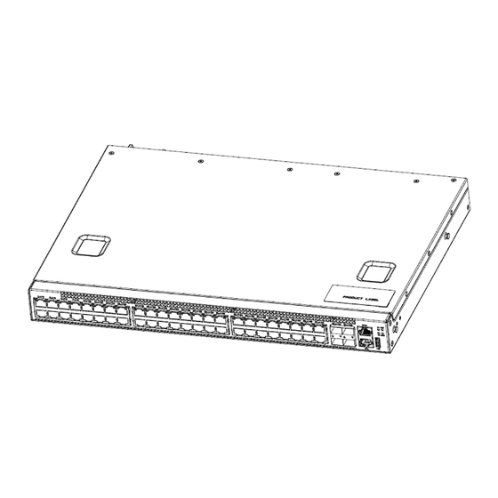
Figure 1-1 Arctica 4804iq Series Switch Figures 1.2.Description of Hardware 1.2.1.Front Panel Front Panel Diagram The front panel descriptions of Arctica 4804iq series switch in the following table. Table 1-1 The front panel descriptions of Arctica 4804iq series switch 10/100/1000Base-T USB2.0... -
Page 4: Back Panel
Figure 1-2 Front Panel of Arctica 4804iq Console description Arctica 4804iq series switches provide a RJ-45 serial console port, the user perform the local and telnet configuration through this port. The console port supports asynchronous mode, set the data bit as 8, the stop bit as 1, the parity bit as none, the default baud rate as 115200bps. - Page 5 Arctica 4804iq Series switch Installation Guide Chapter 1 Introduction Indicator light Panel sign State Meanings Green light Power supply module move always on normally. Power supply P-1 / P-2 Amber light Power make a mistake indicator light always on Put out...
-
Page 6: Port Description
SFPP-10G-LR transceiver SFPP-10G-ER transceiver SFPP-10G-ZR transceiver Arctica 4804iq series swich provide 4 SFP+ ports and support the SFP+ cable(0.5M- 7M). It enhances the flexibility of the network. 1.5.Power Supply Module The following picture is the power supply module of Arctica 4804iq. The whole... -
Page 7: Fan Module
Chapter 1 Introduction Fig 1-5 The sketch map of PSM Arctica 4804iq series switch has one PSM in standard configuration. When two power supplies are at their position, it provides redundancy backups. The maximum power is 200W, the import is 90VAC~264VAC/47HZ~63HZ and the export is 12V +/- 5%. - Page 8 Arctica 4804iq Series switch Installation Guide Chapter 1 Introduction Fixed Port 48 RJ45 ports; 4 SFP+ ports Management Port 1 RJ-45 serial console port 1 RJ_45 managemen Ethernet port Power Input 90~264VAC(47~63Hz) System Consumption 85.2W Operating Temperature 0°C~45°C Storage Temperature -40°C~70°C...
-
Page 9: Installation Notice
2.1.1.Dust and Particles Dust is harmful to the safe operation of Arctica 4804iq series. Dust can lead to electrostatic adherence, especially likely under low relative humidity, causing poor contact of metal connectors or contacts. Electrostatic adherence will result in not only reduced product lifespan, but also increased chance of communication failures. -
Page 10: Temperature And Humidity
Arctica 4804iq Series switch Installation Guide Chapter 2 Installation Notice Average (mg/m³) Max (mg/m³) 0.006 0.03 0.04 0.15 0.05 0.15 0.01 Table 2-2 Environmental Requirements: Particles 2.1.2.Temperature and Humidity Although the switch is designed to use 3 fans, the site should still maintain a desirable temperature and humidity. -
Page 11: Power Supply
Arctica 4804iq Series switch Installation Guide Chapter 2 Installation Notice continued operation and an annual cumulative total of less than 15 days. Formidable operation conditions refers to the ambient temperature and relative humidity value that may occur during an air-conditioning system failure, and normal operation conditions should be recovered within 5 hours. -
Page 12: Rack Configuration
Caution! If a standard 19’’ rack is not available, the Arctica 4804iq series can be placed on a clean level desktop, leave a clearance of 100mm around the switch for ventilation, and do not place anything on top of the switch. - Page 13 Arctica 4804iq Series switch Installation Guide Chapter 2 Installation Notice ■ Do not configure the switch alone in a dangerous situation, ■ Use standard power sockets which have overload and leakage protection. ■ Inspect and maintain the site and the switch regularly.
-
Page 14: Device Installation
Arctica 4804iqSeries switch Installation Guide Chapter 3 Device Installation 3. Device Installation 3.1.Installation Preparation 3.1.1.Verify the Package Contents Please unpack the shipping package and verify carefully the contents inside. 3.1.2.Required Tools and Utilities The required tools and utilities are shown below: ■... -
Page 15: Installing The Power Supply Module
Figure 3-1 Arctica 4804iq series switch install sketch map on the rack using stock Please mount Arctica 4804iq series on the 19’’ rack as below: 1. Attach the 2 brackets on the Arctica 4804iq series with screws provided in the accessory kit. - Page 16 Arctica 4804iqSeries switch Installation Guide Chapter 3 Device Installation One power supply module Installing as below: Figure 3-2 The figure of Arctica 4804iq switch one power supply installing Please install the one power supply module according to the following approach: Take out the power supply module from the little packing box.
-
Page 17: Installing The Fan
And draw the power supply forth. 3.2.3.Installing the Fan Arctica 4804iq switch has 3 fans in standard configuration. Figure 3-5 The figure of Arctica 4804iq series switch installing the fan Please install the fan module according to the following approach:... -
Page 18: Connecting Console
3.2.4.Connecting Console Arctica 4804iq series provide a serial console port. Figure 3-6 Connecting Console to Arctica 4804iq series switch The connection procedure is listed below: Find the console cable provided in the accessory kit. Attach the console cable end to console port of the switch. -
Page 19: Sfp/Sfp+ Transceiver Installation
Chapter 3 Device Installation 3.2.5.SFP/SFP+ Transceiver Installation Arctica 4804iq series provide 48 RJ45 transceiver slots and 4 SFP+ ports. The procedure for installing the SFP+ transceiver is shown below: Step 1: Put on a ESD wrist strap (or antistatic gloves) Step 2: Insert the SFP+ transceiver to the guide rail inside the SFP+ port. -
Page 20: Ac Power Supply Connection
Do not stare at the fiber bore when the switch is in operation. That may hurt your eyes. Figure 3-7 Connect the DAC cable to Arctica 4804iq series switch The connection approach of DAC cable is below: Connect the two side of DAC cable to SFP+ transceiver of Arctica 4804iq switch. -
Page 21: Checking The Switch
Arctica 4804iq series switch uses 220/110VAC power supply by default. Please read the power input specification for the detailed information. Figure 3-8 Connect the power supply cable to the Arctica 4804iq series switch AC Power supply connection procedure is described as below: 1. - Page 22 Arctica 4804iqSeries switch Installation Guide Chapter 3 Device Installation If there are cables at the outside, please ensure the cable is well connected with the lightning protection devices.
Need help?
Do you have a question about the Arctica 4804iq Series and is the answer not in the manual?
Questions and answers