
Related Manuals for Nidac 1 Series


Summary of Contents for Nidac 1 Series
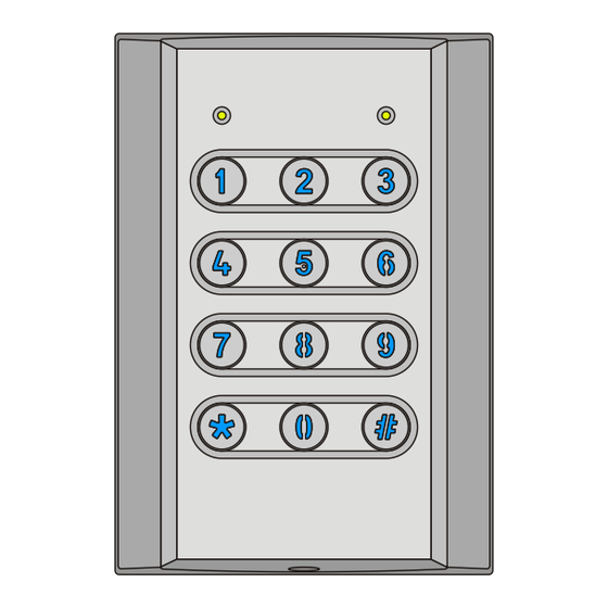
- Page 1 VST43 & VST62 Series 1 Vandal and Weather Resistant Stand Alone Keypads N761 Instruction Manual...
-
Page 2: Table Of Contents
TABLE OF CONTENTS PAGE GENERAL INFORMATION ............1 Features ................1 Package Contents ..............2 Specifications ................ 2 1.3.1 VST43 Dimensions ............3 1.3.2 VST62 Dimensions ............3 INSTALLATION ................4 Mounting ................4 Wiring the VST Keypads ............5 2.2.1 Wire Colours .............. - Page 3 TABLE OF CONTENTS PAGE 4.4.2 Auxiliary Relay Functions ..........15 Setting 911 – Auxiliary Relay Time ........17 Setting 912 – Auxiliary Lock Relay Mode ......17 Setting 913 – Auxiliary REX Input Mode ......17 Setting 914 – DOTL Time ........... 17 Setting 915 –...
-
Page 4: General Information
GENERAL INFORMATION FEATURES • Suitable for indoor and outdoor use. • Durable and stylish metal keypad construction (satin chrome plated zinc die cast). • 10 to 27 Volt D.C. operation. • Controls up to 2 doors. • 2 x 2A SPDT relays. •... -
Page 5: Package Contents
PACKAGE CONTENTS Included in the package for your VST keypad is: 1 x VST43 or VST62 keypad. 1 x Instruction manual (this document). 1 x VST keypad cable with rubber sealing boot. 1 x Hex Allen key to remove screw(s) for fascia. 1 x Mounting template for both VST43 &... -
Page 6: Vst43 Dimensions
1.3.1 VST43 Dimensions 1.3.1 VST62 Dimensions... -
Page 7: Installation
INSTALLATION MOUNTING 1. Use the supplied template to mark the location of the cable exit and mounting screws. Drill out all points as necessary. 2. Using the supplied key remove the hex Allen screw(s) at the bottom of the keypad that secure the fascia to the chassis. 3. -
Page 8: Wiring The Vst Keypads
WIRING THE VST KEYPADS The VST keypads come with a 100cm long AWG-26 removable 12 conductor cable fitted with rubber boot. 2.2.1 Wire Colours There are 12 wires for the VST keypads, not all will be needed for each installation. The unused wires should always be terminated and left unconnected. -
Page 9: Lock Wiring
2.2.2 Lock Wiring 2.2.3 Auxiliary Wiring... -
Page 10: Auxiliary Lock Wiring
2.2.4 Auxiliary Lock Wiring 2.2.5 Tamper Output... -
Page 11: Fail Secure Lock Wiring With Tamper Security
2.2.6 Fail Secure Lock Wiring with Tamper Security This method of wiring the lock ensures that even if the keypad is forcibly removed from the wall the lock cannot operated by manipulation of the wiring. The relay, reset switch and power supply are required to be situated securely inside where they and their wiring cannot be accessed by someone on the outside. -
Page 12: Operation
OPERATION LED INDICATION There are 2 LEDs on the VST keypads that are used to indicate different conditions. Throughout this manual the left LED will be referred to as the Mode LED and the right as the Status LED. The symbols used in this manual for the LEDs are: ... -
Page 13: Status Led In Operating Mode
3.1.2 Status LED in Operating Mode In operating mode the Status LED indicates the conditions below. - Neither relay is currently active. - Lock relay is currently active (door unlocked). Green - Auxiliary relay is currently active (door unlocked). ... -
Page 14: User Codes
The default Manager code is disabled when a new Manager code is programmed; it will be enabled again if all programmed manager codes are deleted. The default Lock and Auxiliary codes are disabled when any new code is programmed; they will be enabled again if all programmed user codes are deleted. -
Page 15: Code Usage
CODE USAGE User codes can be used to either control the Relays (Door Access) or perform Advanced Code Functions. 3.4.1 Door Access The most common use of a code is to control a door lock connected to the VST keypad. To do this simply enter the code on the VST keypad, the ... -
Page 16: Installer Setting Programming
INSTALLER SETTING PROGRAMMING The factory default installer code is 9999. To enter installer mode press <installer code> (the final is not required when using fixed length codes) The keypad will beep 3 times and the Mode LED will alternately flash Green Orange () -
Page 17: Setting 901 - Lock Relay Time
Setting 901 – Lock Relay Time Allowed Values = 0 - 255 Default value = 10 The value for this setting is the time that the Lock relay activates for, in seconds, when a valid code is used or the REX input is activated. Note that a value of 0 for this setting will cause the Lock relay to be in latching mode, making it alternate between open and closed on each code usage. -
Page 18: Auxiliary Input Functions
Mode Auxiliary Input Function Auxiliary Relay Function Door Open Too Long Alarm Door Monitor Door Monitor Door Forced Open Alarm Door Monitor DOTL and DFO Alarm Door Monitor Shunt Auxiliary Lock REX Auxiliary Lock Lockout Standard Users Auxiliary Lock Key Lockout Standard Users Lockout Standard Users Direct Shunt... - Page 19 Direct Shunt - The Auxiliary relay activates for Auxiliary Relay Time each time a valid code or REX is used to operate the Lock relay. This function is generally used to bypass (shunt) a door monitor sensor or an alarm sensor covering the door area. Simply wire the Auxiliary relay in parallel with the NC sensor and a valid code usage or REX will shunt the sensor allowing door access without triggering an alarm connected to the sensor.
-
Page 20: Setting 911 - Auxiliary Relay Time
Setting 911 – Auxiliary Relay Time Allowed Values = 0 - 255 Default value = 10 The value for this setting is the time, in seconds, that the Auxiliary relay uses for Auxiliary Lock control, key (door bell) activation, Door Forced open alarm, Shunt or Direct Shunt. -
Page 21: Setting 915 - Auto Relock Enabled
Setting 915 – Auto Relock Enabled Allowed Values = 0 - 1 Default value = 0 0 = Disabled, 1 = Enabled. If Auto Relock is enabled and the Auxiliary relay is set as DOTL and/or DFO (Auxiliary Mode = 4, 5 or 6) the VST keypad will relock the door 1 second after it detects the door has been opened via the sensor connected to the Auxiliary Input. -
Page 22: Setting 923 - Tamper Sensitivity
4.13 Setting 923 – Tamper Sensitivity Allowed Values = 0 - 3 Default value = 2 The VST keypads are fitted with a sensitive tamper detection device that can detect when the unit has been removed from its mounted position. In some extreme circumstances it may be necessary for the sensitivity of this device to be adjusted. -
Page 23: Setting 934 - Latching Override Cancelled By Code Use
4.17 Setting 934 – Latching Override cancelled by code use Allowed Values = 0 - 3 Default value = 0 This setting is used to determine if the Latching Override function can be cancelled by use of a code or whether the advanced code function is required. -
Page 24: Setting 969 - Reset Keypad To Factory Defaults
4.20 Setting 969 – Reset keypad to factory defaults Allowed Value = 246 Enter 246 into this setting location to reset the keypad back to factory defaults. NOTE programming this setting will erase all existing codes. The new value for this setting needs to be confirmed by entering the current installer code then ... -
Page 25: User Code Programming
USER CODE PROGRAMMING User code programming is performed by entering the manager mode. The factory default manager code is 1111. Note that the default manager code will be disabled once a new manager code is programmed. To enter manager mode press <manager code> (the final ... -
Page 26: Adding User Codes
Adding User Codes Simplified sequences for adding codes are given in sections 5.1.1, 5.1.2 and Appendix B. To add a user code use one of the following sequences:- <user location> <code> When programming a standard user to control the Lock relay ... -
Page 27: Regular Method To Add User Code
5.1.1 Regular Method to Add a User Code Add a Standard User Code for Lock Control <user location> <code> Add a Standard User Code for Auxiliary Lock Control <user location> <code> Add a Standard User Code for Lock & Auxiliary Lock Control ... -
Page 28: Bulk Add User Codes Method
5.1.3 Bulk Add User Codes Method Often when initially setting up a system many user codes need to be added. The bulk add method allows multiple codes to be added to consecutive user locations with the minimum number of key presses. NOTE: When using bulk add there is no indication as to whether the user location being programmed already contains a code, and as such any existing code will be overwritten with new one. -
Page 29: Deleting User Codes
Deleting User Codes The sequences for deleting codes together with the Status LED indication are:- <user location> - to delete a code from a known location. <code> - to delete a known code from any location. ... -
Page 30: Enable/Disable Installer Code
ENABLE/DISABLE INSTALLER CODE Once the system has been commissioned and all the installer mode settings are correct, it is highly recommended that the Installer Code be disabled. The reason for this is to ensure that someone who knows the installer code cannot use it to set the relay mode and in effect open the door without using a user code. -
Page 31: Forgotten Installer Or Manager Code
FORGOTTEN INSTALLER OR MANAGER CODE In the event that the installer or manager code has been forgotten, the default codes can be enabled by performing the following steps:- 1) Remove power from the VST keypad. 2) Disconnect any connections to the REX (dark green) and Auxiliary Input (white) wires. -
Page 32: Appendix A: Installer Setting Summary
APPENDIX A: INSTALLER SETTING SUMMARY The factory default installer code is 9999. To enter installer mode press <installer code> (the final is not required when using fixed length codes) The keypad will beep 3 times and the Mode LED will alternately flash () Green/Orange Program installer settings using ... -
Page 33: Appendix B: User Code Programming Summary
APPENDIX B: USER CODE PROGRAMMING SUMMARY The factory default manager code is 1111. To enter manager mode press <manager code> (the final is not required when using fixed length codes) Green The keypad will beep 5 times and the Mode LED will be flashing Using Regular Method Add a Standard User Code for Lock Control ... - Page 34 Add a Primary User Code for Auxiliary Lock Control <code> Add a Manager Code for Lock Control <code> Delete a code <code> Delete all User Codes Use ...
-
Page 35: Appendix C: Quick Setup Guide
APPENDIX C: QUICK SETUP GUIDE Set a new Installer code 1. Enter Installer Mode 2. Set new installer code <new installer code> 3. Now set any other installer options 4. - Page 36 (excluding accidental or malicious damage) under the 36 month warranty offered from the date of purchase. As NIDAC Security Pty. Ltd. or its agents do not perform the final installation, inspection or training in the use of this product, they cannot be held liable for injury, loss or damage directly or consequentially arising from the use or misuse of this product.
Need help?
Do you have a question about the 1 Series and is the answer not in the manual?
Questions and answers