
Related Manuals for Bray 5A Series


Summary of Contents for Bray 5A Series
- Page 1 SERIES 5A AND 5B INTRINSICALLY SAFE VALVE STATUS MONITOR Installation, Operation and Maintenance Manual BRAY.COM THE HIGH PERFORMANCE COMPANY...
-
Page 3: Table Of Contents
17. Basic Tools ......... . . 16 FOR MORE INFORMATION ON THIS PRODUCT AND OTHER BRAY PRODUCTS... -
Page 4: Safety Instructions - Definition Of Terms
Series 5A and Series 5B I.S. Valve Status Monitor Installation, Operation and Maintenance Manual Read and Follow These Instructions Save These Instructions 1. Safety Instructions - Definition of Terms Indicates a potentially hazardous situation which, if not avoided, could result in death or serious injury. -
Page 5: Part Numbering System Reference Chart
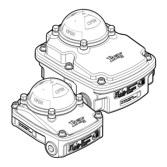
5. Introduction 6. Principle of Operation The Bray Series 5A and 5B Intrinsically Safe Bray Series 5A and 5B I.S. VSMs are comprised of a Valve Status Monitors (VSMs) provide visual and NEMA Type 4/4X, IP66/67 housing (resin housings electrical indication of position of any VDI/VDE are IP66/67/68 (1 meter, 1 hour) with external 3845 compliant quarter-turn device. -
Page 6: Hazardous Locations
NOTICE II 2G Ex ia IIC Gb T6 IECEx IECEx UL 18.0073X The Bray Series 5A and 5B I.S. VSMs are compliant Ambient 1G: -25°C ≤ Ta ≤ 49°C to the IEC/EN 60079-11 section 6.3.13 dielectric 2G: -25°C ≤ Ta ≤ 65°C strength requirement. -
Page 7: Mounting
6. Place lock washers on foot plate mounting bolts. 9.1 Adjustable Bracket 7. Attach two mounting bracket foot plates to Bray's 3 piece adjustable bracket is designed to the quarter-turn device. mount on both NAMUR 30x80 and 30x130 pads. a. Tighten mounting bracket foot plates to Installation is as follows: 44.3 in-lbs. -
Page 8: Fixed Bracket
Installation, Operation and Maintenance Manual 9.2 Fixed Bracket 9.2.1 Stainless Steel Bracket Bray's single piece stainless steel bracket is used for NAMUR pattern 30 x 80. Installation is as follows: 1. Attach mounting bracket and nylon washers to the VSM using mounting bracket bolts. -
Page 9: Accessing Internal Components
Installation, Operation and Maintenance Manual 10. Accessing Internal 11. Field Wiring Components Bray Series 5A and 5B I.S. are assembled with numbered terminal blocks on a printed circuit Access to the S5AB internals is done by removing board designed to conform to Intrinsically Safe the cover from the unit. - Page 10 Series 5A and Series 5B I.S. Valve Status Monitor Installation, Operation and Maintenance Manual Bray Series 5A and 5B I.S. VSMs should be wired as follows: 1. Remove the cover of the VSM. To ensure intrinsic safe operation, use cable ties to mount field wiring to the printed circuit board.
-
Page 11: Reversal Of Visual Indication
NOTICE Ensure that open and close cams are properly set after any modification to visual indication. Bray Series 5A and 5B I.S. VSM visual indication can be reversed as follows: 1. Remove all four Indicator dome bolts with lock washers. -
Page 12: Position Adjustment
Series 5A and Series 5B I.S. Valve Status Monitor Installation, Operation and Maintenance Manual 13. Position Adjustment 4. Release the cam and allow the locking spring to re-engage the cam with the fixed cam A single or doubled lobed cam is provided for every holder. -
Page 13: Troubleshooting Chart
Series 5A and Series 5B I.S. Valve Status Monitor Installation, Operation and Maintenance Manual 14. Troubleshooting Chart Problem Possible Cause Solutions Wiring is not connected inside Rewire field wiring and check applied torque to terminal block Cams are set outside of actuator Adjust cam position Signal is not received range... -
Page 14: Exploded Views
Series 5A and Series 5B I.S. Valve Status Monitor Installation, Operation and Maintenance Manual 15. Exploded Views Exploded View - 5A - Aluminum Trim... -
Page 15: Exploded View - 5A - Resin Trim
Series 5A and Series 5B I.S. Valve Status Monitor Installation, Operation and Maintenance Manual Exploded View - 5A - Resin Trim... -
Page 16: Exploded View - 5B Aluminum Trim
Series 5A and Series 5B I.S. Valve Status Monitor Installation, Operation and Maintenance Manual Exploded View - 5B Aluminum Trim... -
Page 17: Exploded View - 5B Resin Trim
Series 5A and Series 5B I.S. Valve Status Monitor Installation, Operation and Maintenance Manual Exploded View - 5B Resin Trim... -
Page 18: Replacement Parts
Series 5A and Series 5B I.S. Valve Status Monitor Installation, Operation and Maintenance Manual 16. Replacement Parts 16.1 Replacement Parts Aluminum Housing Description Imperial Metric Dome Bolts Dome Washer Dome Assembly 5B0000-22900536 5B0000-22950536 Dome Gasket Indicator Assembly Cover Bolt 5B0000-22901536 5B0000-22951536 Cover Bolt Washer 16.2 Replacement Parts Resin Housing... - Page 19 Series 5A and Series 5B I.S. Valve Status Monitor Installation, Operation and Maintenance Manual...
- Page 20 Buenos Aires HEADQUARTERS All statements, technical information, and recommendations in this bulletin are for general use only. Consult Bray representatives Bray International, Inc. or factory for the specific requirements and material selection for your intended application. The right to change or modify 13333 Westland East Blvd.
Need help?
Do you have a question about the 5A Series and is the answer not in the manual?
Questions and answers