
Related Manuals for Bray 5C Series

Summary of Contents for Bray 5C Series
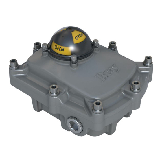
- Page 1 SERIES 5C VALVE STATUS MONITOR Installation, Operation and Maintenance Manual BRAY.COM THE HIGH PERFORMANCE COMPANY...
-
Page 3: Table Of Contents
Exploded View - 5C ........12 FOR MORE INFORMATION ON THIS PRODUCT AND OTHER BRAY PRODUCTS... -
Page 4: Safety Instructions - Definition Of Terms
Series 5C Valve Status Monitor Installation, Operation and Maintenance Manual Read and Follow These Instructions Save These Instructions 1. Safety Instructions - Definition of Terms Indicates a potentially hazardous situation which, if not avoided, could result in death or serious injury. Indicates a potentially hazardous situation which, if not avoided, may result in minor or moderate injury. -
Page 5: Part Numbering System Reference Chart
Series 5C Valve Status Monitor Installation, Operation and Maintenance Manual 4. Part Numbering System Reference Chart Series Housing Product Switch Configuration Trim -126 5X – Designates Housing Size Type 4, 4x; IP66/67/68 (1 meter for 1 hour); Max 6 switches H –... -
Page 6: Introduction
6. Principle of Operation prevent foreign matter from entering the unit. To prevent condensation from forming inside Bray Series 5C VSMs are comprised of a hazardous these units, maintain a near constant external location housing with NEMA Type 4, 4x and IP... -
Page 7: Fixed Bracket
Series 5C Valve Status Monitor Installation, Operation and Maintenance Manual 9.2 Fixed Bracket Bray's single piece bracket is used for NAMUR pad 30 x 80. Installation is as follows: 1. Attach mounting bracket and nylon washers 6. Place lock washers on foot plate mounting to the VSM using mounting bracket bolts. -
Page 8: Accessing Internal Components
To reduce the risk of ignition, the cover must be kept tightly closed. Substitution of Bray supplied S5C cover mounting bolts and washers is not permitted. 1. Ensure o-ring is seated in the o-ring groove 2. Press on cover insuring captive bolts are aligned with the bolt holes 3. -
Page 9: Field Wiring
Series 5C Valve Status Monitor Installation, Operation and Maintenance Manual 11. Field Wiring Bray Series 5C VSMs may be assembled with either a 12-pole terminal block with numbered terminal For NEC 500 hazardous locations: strip marker or with two numbered and lettered... -
Page 10: Reversal Of Visual Indication
Installation, Operation and Maintenance Manual 12. Reversal of Visual Indication Visual indication can be reversed per application Bray Series 5C VSM visual indication can be reversed requirements without the need to re-mount the as follows: VSM. This may also be appropriate if the standard 1. -
Page 11: Position Adjustment
Series 5C Valve Status Monitor Installation, Operation and Maintenance Manual 13. Position Adjustment 4. Release the cam and allow the locking spring to re-engage the cam with the fixed cam A single or doubled lobed cam is provided for every holder. -
Page 12: Switch Ratings
Series 5C Valve Status Monitor Installation, Operation and Maintenance Manual 14. Switch Ratings Mechanical Switches Mechanical Switches SPDT SPDT Low Power DPDT-DB Switch Option Switch Ratings 10A, 250V ac 0.1A, 125V ac 10A, 250V ac 1/2 HP, 250V ac 0.1A, 30V dc 3/4 HP, 250V ac 0.25A, 250V dc 1mA, 4V ac/dc min... -
Page 13: Basic Tools
Series 5C Valve Status Monitor Installation, Operation and Maintenance Manual 15. Basic Tools Common To All Units Terminal Connections Screwdriver, ¼” tip flat blade All switches, terminal strip Screwdriver, No. 1 Phillips Indicator Dome Wrench, 8mm Cover Bolt Hex Key, 6mm Ground screw Screwdriver, No. -
Page 14: Exploded Views
Series 5C Valve Status Monitor Installation, Operation and Maintenance Manual 17. Exploded Views Exploded View - 5C... - Page 15 Series 5C Valve Status Monitor Installation, Operation and Maintenance Manual Replacement Parts Description Part Dome Bolts Dome Washer Dome Assembly 5C0000-22900536 Dome Gasket Indicator Assembly 1/2" or M20 Conduit Plug See below for replacement conduit plugs with certifications 3/4" or M25 Conduit Plugs Cover Bolt 5C0000-22901536 Cover Washer...
- Page 16 Buenos Aires HEADQUARTERS All statements, technical information, and recommendations in this bulletin are for general use only. Consult Bray representatives Bray International, Inc. or factory for the specific requirements and material selection for your intended application. The right to change or modify 13333 Westland East Blvd.
Need help?
Do you have a question about the 5C Series and is the answer not in the manual?
Questions and answers