Table of Contents
Advertisement
Advertisement
Table of Contents

Related Manuals for Supmeter BST106-M60S(L)


Summary of Contents for Supmeter BST106-M60S(L)
- Page 1 BST106-M60S[L] Guide Rail Type Weighing / Force Measuring Control Module Weight/Force Display, Peak Value Detection / Display Holding, Auto Weight-checking, Setpoint DO Output, AO/Digit Transmission Operation Manual V3.0 Changsha Supmeter Technological Co.,Ltd.
- Page 2 Preface Thank you very much for your purchase! This manual covers safety precaution, technical specifications, interfaces, installation& user connection, functions&operation and so on. In order to make the product running at its best, please read this manual in advance, and reserve it for the future reading. The technology update, function enhancement and quality improvement may lead to some differences between this manual and the physical product, please understand.
-
Page 3: Table Of Contents
Contents 1. SAFETY PRECAUTION .........................3 2. TECHNICAL SPECIFICATIONS ....................4 3. USER INTERFACE ..........................6 3.1 U ........................6 NTERFACE IAGRAM 3.2 S ..........................6 TATE NDICATION 3.3 K ..........................7 EYPAD PERATION 3.4 A ............................7 LARM IGNS 4. INSTALLATION&CONNECTION ....................8 4.1 I ............................ -
Page 4: Safety Precaution
1. Safety Precaution Application environment Make sure that this product works under the environment where is accord with the technical specifications. Do not open the shell before power-off. Cable Laying Weighing signal, analog signal and communication signal cables should be laid in pipes, and do not lay them together with power cables. -
Page 5: Technical Specifications
2. Technical Specifications Executing Standards PRC GB/T 7724-2008《National Standard for Electronic Weighing Meter》. PRC JJG 649-2016《National Verification Regulation for Digital Weighing Indicators (Weighing Indicators)》. OMIL R76-1: 2006《Non-automatic Weighing Instruments》International Recommendation. ○ Accuracy Grade: Ⅲ . ... - Page 6 COM3: Optional CANBUS. Connectable: Host IPC/PLC and LED Remote Display. Operating Specification Operating Voltage: DC12~24V. Max. Power Consumption: 3W. Outline Size: 71.5× 113× 57.9mm [W× H× D]. Guide rail type installation. Guide Rail Groove Size: 35× 1.6 mm [W× H× D]. ...
-
Page 7: User Interface
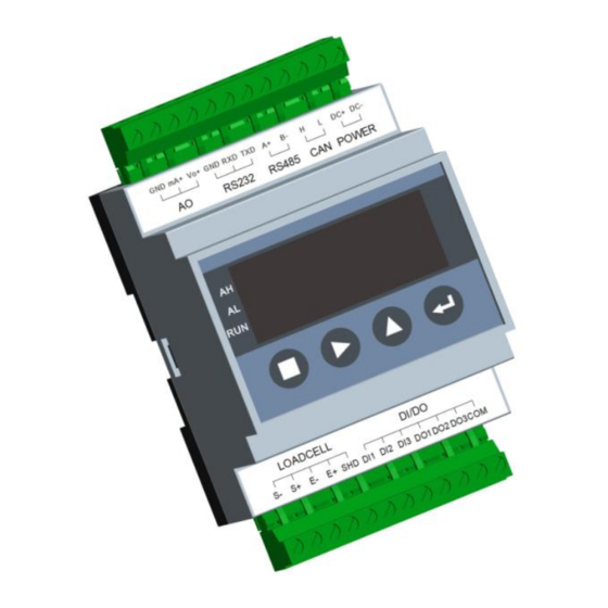
3. User Interface 3.1 User Interface Diagram GND mA+ Vo+ GND RXD TXD A+ L DC+ DC- RS232 RS485 CAN POWER ■ ▲ ► LOADCELL DI/DO E+ SHD DI1 DI2 DI3 DO1 DO2 DO3 COM 3.2 State Indication LED light Description Note [AH]... -
Page 8: Keypad Operation
3.3 Keypad Operation If there is not any keypad operation in one minute and it’s not in the processes of ‘F2 System Calibration’ & ‘F6 Factory Adjustment’, the controller will return to ‘Main Display Interface’ automatically. Key Name Function Description 【MENU】... -
Page 9: Installation&Connection
4. Installation&Connection 4.1 Installation 71.5 57.9 Plastic Fastener Outline Size Guide Rail Groove Size W× H× D[mm] W× D[mm] 71.5× 113× 57.9 35× 1.6... -
Page 10: Terminal
4.2 Terminal LOADCELL DI/DO E+ SHD DI1 DI2 DI3 DO1 DO2 DO3 COM Description LOADCELL Loadcell Port Weighing Signal Input +. Weighing Signal Input -. Excitation Voltage -. Excitation Voltage + [DC5V]. Shield Ground. DI/DO Switch Input/Output Port [Definable] Switch Signal Input 1. Switch Signal Input 2. - Page 11 GND mA+ Vo+ GND RXD TXD A+ L DC+ DC- RS232 RS485 CAN POWER Description POWER DC12 24V Power Input Port DC Input -. DC Input +. CAN [Optional] CANBUS Digital Communication Port [COM3] Data -. Data +. RS485 RS485 Digital Communication Port [COM2] Data -.
-
Page 12: Operation Procedure
5. Operation Procedure Connection & Power on Scale Setting Zero Calibration [Data Calibration] Load Calibration [Segmenting Correction] Zero Auto-tracking Limit & Manual/Auto Zero Limit Setting Setpoint Setting Other Settings Key-locking... -
Page 13: Functions&Operation
6. Functions&Operation 6.1 Main Display Interfaces 【▲】: Display interface switch. 【►】 6.1.1 Real-time Weight Value and Percent [L] Weight Percent L% = (Weight / Scale Capacity)×100%. 6.1.2 Real-time Weight, Peak Hold Value or Checking-weight Value [P] [203]=0: P=0. [203]=1: P=Weight Peak Value. [203]=2: P=Checking-weight Value. -
Page 14: Real-Time Weight, Vo Output Value [Vo]
6.1.4 Real-time Weight, VO Output Value [Vo] VO: 0.00~10.00V. 6.1.5 Real-time Weight, Communication State [Co] gd: Normal; no: No Communication; Er: Error. -
Page 15: Main Menu
6.2 Main Menu Main Menu Second Menu Sign Function Sign Description -SCAL Scale parameters setting. -CALP- Calibration parameters setting. Parameter F1.SEt -SEtP- Setpoint parameters setting. Setting -SErP- Communication parameters setting. -dISP- User interface parameters setting. Zero Calibration without loading on the weigher to correct Zero -ZEro- Value. - Page 16 Main Menu Second Menu Special for manufacturer. 【mV】Exfactory Span Adjustment: Use standard weighing test -SPAn- equipment to adjust the weighing signal interface for normalizing Span Coefficient to 1. -AdtS- Weighing Signal Linearity Test. AO [0~20mA] Zero/Full Adjustment. Factory -AVZF- F6.FAC VO [0~10V] Zero/Full Adjustment.
-
Page 17: F1-Set Parameter Setting
6.3 F1-SET Parameter Setting 6.3.1 Weighing Parameters (SCAL) Sign Range Default Description Weight Unit 0: None 1: kg 2: t 3: g Decimal Point Position 0: ooooo 1: oooo.o ooo.oo 2: ooo.oo 3: oo.ooo 4: o.oooo Scale Capacity Max. allowed loading weight of the load receptor. 1~99999 10000 Scale Capacity ≤... - Page 18 Sign Range Default Description Sampling Frequency [Hz] 0: 5 Hz 1: 200 Hz 2: 400 Hz 3: 800 Hz 4: 1600Hz 5: 3200Hz Anti-vibration Digital Filter1 Set Value Cutoff Frequency None 11.2Hz 8.0Hz 5.6Hz 4.0Hz 2.8Hz 2.0Hz 1.4Hz 1.0Hz 0.7Hz Weight Display Smooth Filter2 The bigger set value of Filter2 will make the weight 1~128...
-
Page 19: Calibration Parameters (Calp)
6.3.2 Calibration Parameters (CALP) Sign Range Default Description Zero Auto-tracking Permission 0: oFF 1: on [Only after weight being stable and the zero variation in ‘Zero Auto-tracking Time’ is within the range of ‘Zero Auto-tracking Limit’, the result of Zero Auto-tracking will be valid] 0.1~9.9 Zero Auto-tracking Time [s] 0.1~50.0... - Page 20 Sign Range Default Description Correction Point’s Loading Weight 1~10 1000 2000 Inputted Loading Weight value for Segmenting 3000 Correction. 4000 Demand: L1≤L2≤…≤L10. 1~99999 5000 Only for query. 6000 7000 8000 9000 LA[L10] 10000 Correction Point’s AD Value 1~10 10000 20000 AD Value detected via Segmenting Correction.
-
Page 21: Setpoint Parameters (Setp)
6.3.3 Setpoint Parameters (SEtP) Sign Range Default Description 0~99999 1000 Weight Setpoint 1 0~99999 9000 Weight Setpoint 2 Non-load Zero Range Peak Value Detection: ‘Weight > Non-load Zero Range’ for triggering the peak value detection process. ‘Weight ≤ Non-load Zero Range’ for stopping the peak value detection process. - Page 22 Sign Range Default Description DO Bounce-back Delay Time [s] Used for avoiding that the DO alarm switch turns on and off frequently with its related real-time data being at the critical point. Min. Interval Time for Peak Value Detection [s] Only after the time delayed, the triggered peak value detection process is allowed to be stopped by ‘Weight ≤...
- Page 23 Sign Range Default Description DI1/DI2/DI3 Signal 0. ≡ZEro [Manual Zero without Power-down Protection] 1. -ZEro [Zero Calibration with Power-down Protection] 2. -CLS- [Clear Screen] 3. Id [Weight-Checking Photo-electric Identification for identifing the unchecked product entering the weigher] 4. StSP [Start/Stop Peak Value Detecting or Weight-checking Process] 5.
-
Page 24: Communication Parameters (Serp)
6.3.4 Communication Parameters (SErP) Sign Range Default Description 0~99 Communication Address COM1/COM2 Baud Rate 9600bps 19200bps 2: 115200bps [1152d] COM1/COM2 Parity Check 0. none None Check] 1. EVEn [Even Check] 2. odd [Odd Check] COM1/COM2 Communication Mode 0. HASC [Host-slave, Modbus ASCII] 1. -
Page 25: Display Parameters (Disp)
6.3.5 Display Parameters (dISP) Sign Range Default Description 0.01~1.00 0.20 Display Refreshing Time [s] Auto-Locking 0: oFF 1: on [If there is not any keypad operation in one minute and it’s not in the processes of ‘F2 System Calibration’ & ‘F6 Factory Adjustment’, the controller will lock the keypad and return to ‘Main Display Interface’... -
Page 26: A Sample Of Parameter Setting
6.3.6 A Sample of Parameter Setting Modify the parameter ‘[102] Scale Capacity’. Main Display Interface ■ 【 】+【►】 【▲】: F1-SEt 【 】+【►】 【▲】 【 】+【►】 【▲】 【 】 【►】: Moving cursor; 【▲】: Digit input. ■ 【 】: Exit 【 】: Save... -
Page 27: F2-Cal System Calibration
6.4 F2-CAL System Calibration After doing ‘System Calibration’, Tare Weight value will return to zero automatically. 6.4.1 Zero Calibration (ZEro) Do Zero Calibration without loading on the weigher and save the new Zero Value. Main Display Interface ■ 【 】+【►】 【▲】: F2-CAL 【... -
Page 28: Data Calibration (Data)
6.4.2 Data Calibration (dAtA) Input the specification parameter values of loadcell [Total Capacity and Output Sensitivity] according to the actual configuration of the weighing system to correct Span Coefficient. If there is no access to get the specification parameter values for Data Calibration, then it’s necessary to do Load Calibration. Main Display Interface ■... - Page 29 【►】 【▲】: 105: New Span Coefficient value. oLd: Original Span Coefficient value. Sr: Span Correction Ratio = New Value / Original Value. ■ 【 】: Exit 【 】: Save Note: Total Capacity of Loadcells = Loadcell Capacity × Quantity. ...
-
Page 30: Load Calibration (Load)
6.4.3 Load Calibration (LoAd) After doing Data Calibration, if there are conditions for Load Calibration, do Load Calibration with loading standard weight on the weigher to correct Span Coefficient further for higher weighing accuracy. The loading weight should be bigger than 50% of Scale Capacity value. Main Display Interface ■... -
Page 31: Segmenting Span Correction (Segc)
6.4.4 Segmenting Span Correction (SEgC) After doing Zero Calibration and Load Calibration [or Data Calibration], it’s allowed to do Segmenting Span Correction with loading standard weight on the weigher by 10 Correction Points to get Span Correction Ratio of 10 linearity segments for higher weighing accuracy. Main Display Interface ■... -
Page 32: F5-Loc Key-Locker
6.5 F5-LOC Key-locker 6.5.1 Key-unlocking (oPEn) Main Display Interface ■ 【 】+【►】 【▲】: F5-Loc 【 】+【►】 【▲】: -oPEn- 【 】 【 】: If inputted password is correct, Key-unlocking will be valid. 6.5.2 Key-locking (Locc) Main Display Interface ■ 【 】+【►】 【▲】: F5-Loc 【... -
Page 33: Password Set (Pass)
6.5.3 Password Set (PASS) Main Display Interface ■ 【 】+【►】 【▲】: F5-Loc 【 】+【►】 【▲】: -PASS- 【 】 【 】 If inputted is Operator Password, this operation interface will be skipped; if inputted is Administrator Password, ‘Administrator Password [AP]’ or ‘Operation Password [oP]’ can be modified via 【►】 【▲】. -
Page 34: Appendix A. Register Table Of Host-Slave Modbus[Ascii/Rtu]
Appendix A. Register Table of Host-Slave MODBUS[ASCII/RTU] Command Data Name Type Address Attribute Description [HEX] Real-timeWeight Long 40001 Real-time Weight Preset Parameter [203]=0. Weight Peak Value Long 40003 Preset Parameter [203]=1. Checking-weight Preset Parameter [203]=2. 40005.0 1: Running State. 1: Peak Value Detection Finished or 40005.1 Weight-checking Finished. - Page 35 Command Data Name Type Address Attribute Description [HEX] 40007.0 1: DO1 ON; 0: DO1 OFF. 40007.1 1: DO2 ON; 0: DO2 OFF. 40007.2 1: DO3 ON; 0: DO3 OFF 40007.3 40007.4 40007.5 40007.6 40007.7 DO State UnShort 40007.8 40007.9 40007.10 40007.11 40007.12 40007.13...
- Page 36 Command Data Name Type Address Attribute Description [HEX] UnLong 40015 Non-load Zero Range UnShort 40017 03/06 Weight Setpoint 1 UnLong 40018 03/10 Weight Setpoint 2 UnLong 40020 03/10 Weight Peak Value UnLong 40022 UnLong 40024 03/10 0: Real-time Weight. Data Compared with UnShort 40026 03/06...
-
Page 37: Appendix B. Data Frame Format Of Continuous Sending [Ascii]
Appendix B. Data Frame Format of Continuous Sending [ASCII] Field Name Code Description Example START [Byte1] Overload Weighing State Stable [Byte2] Motion Unused Weight Weight Peak Value or Checking-weight Value Data Name [Byte3] Unused Unused Unused Unused 2B/2D Sign Weight Value 30~39 Decimal Point ‘.’... - Page 39 2014F108-43 CPC16/042376 Changsha Supmeter Technological Co., Ltd. Address: Building A6, Lugu International Industrial Park, Changsha, 410205, China Tel: +86 731 85115100 Fax: +86 731 85158100 Website: www.supmeter.com E-mail: supmeter@supmeter.com...
Need help?
Do you have a question about the BST106-M60S(L) and is the answer not in the manual?
Questions and answers