Table of Contents
Advertisement
Advertisement
Table of Contents

Related Manuals for HydroTherm DYNAMIC-SS/X8/OP


Summary of Contents for HydroTherm DYNAMIC-SS/X8/OP
- Page 1 Welcome to the future of hot water. DYNAMIC - SS/X8/OP DYNAMIC - SS/X8/C...
- Page 2 You are now the proud owner of Australia’s best value, best performing heat pump. We spent over three years designing and developing the Hydrotherm range to ensure that each unit will provide years of trouble free operation. However, in order to perform optimally it is important to ensure that your Hydrotherm is installed and operated in-line with the instruction found in this manual.
-
Page 3: Table Of Contents
CONTENTS Symbols used in these instructions 1.0 PARTS & CONSTRUCTION SCHEMATIC....4 Observe the following safety instructions: 1.1 Dimensions 1.2 Schematics Please Note: Warning about possible dangers. 2.0 INSTALLATION INSTRUCTIONS..........2.1 Delivery Note: Important information 2.2 Base and tips. 2.3 Airflow 2.4 Tariffs Note: Carefully read these operating... -
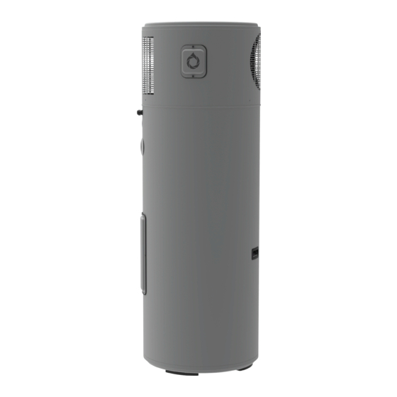
Page 4: Parts & Construction Schematic
1.0 PARTS & CONSTRUCTION SCHEMATIC DIMENSIONS DYNAMIC-SS/X8/OP & DYNAMIC-SS/X8/C 645mm Condensate Drainage Relief Valve Port Hot Water Outlet Access Cover Cold Water Outlet... - Page 5 SCHEMATIC DYNAMIC-SS/X8/OP & DYNAMIC-SS/X8/C 1. Top Lid 2. Upper Cover 3. Electronic Main Board 14,15 4. Electronic Anode Transformer 5. Fan Capacitor 6. AC to DC Transformer 7. Compressor Run Capacitor 8. Compressor Starter Cap 9. Compressor Wiring 3,4,5,6,13 Harness 10.
-
Page 6: Installation Instructions
• The Hydrotherm should be installed so that the control interface is accessible to users and that there is clear access to the electrical panel at the back of the system. Where incorrect installation has occurred warranties... -
Page 7: Airflow
Min. panel should always Min. 2160mm 100mm be accessible. (from base to rooftoop) Concrete base 0° tilt Diagram 1: Side profile of Hydrotherm installation requirements. Min. 300mm Min. Min. 600mm 600mm Diagram 2: Front profile of Hydrotherm installation requirements. -
Page 8: Tariffs
The Continuous tariff is what every household connected to the grid has as a minimum. If you would like to utilize a Solar PV system to run your Hydrotherm system on, this is usually the only tariff available to do so. -
Page 9: Plumbing Schematics
3.0 PLUMBING SCHEMATICS The following instructions and schematics have taken into account standards AS4324, AS4020, AS1056.1, AS/NZS2712, AS/NZ3350.240/30/30.2, AS3498 and represents an optimum installation procedure for this unit however to ensure minimum requirements are met all local regulations should be adhered too. 3.1 DYNAMIC CONNECTION DIMENSIONS AND COMPONENTS Cold water supply outlet... -
Page 10: Plumbing Installation
4.0 PLUMBING INSTALLATION PLUMBING CONNECTIONS 1. Cold Water Supply Outlet • The cold water supply connection is a 3/4” female thread. • The cold water supply should be connected to RP 3/4” socket. • The cold water supply outlet can also act as a drainage point for emptying the system. 2. - Page 11 4. Pressure & Temperature Relief (PTR) valve • The system is supplied with a loose Pressure & Temperature Relief (PTR) valve appropriate to the pressure rating of the water heater tank. If the PTR valve is not present please contact your supplier. The valve rating is 700kPa.
- Page 12 • The non-return valve can be combined with a PRV valve to form a duo valve as shown in the above schematic. Filling The System • Once the Hydrotherm has been connected in accordance to section 3.0 and 4.0 of this handbook, the tank can be filled and pressurized.
-
Page 13: Electrical Connections
5.0 ELECTRICAL CONNECTION Only qualified electricians may carry out the installations of the Hydrotherm heat pump to main power in accordance with the following instructions. ELECTRICAL SCHEMATIC C1/2 C1/2 C3/4 N02 No3 No4 C3/4 Tx/Rx GND B4 Key/spv C1/2 C1/2 C3/4... -
Page 14: Pre-Connection & Regulations
• Before any work can commence ensure that the heater is isolated from the power supply at the control panel. • The Hydrotherm heat pump is designed for permanent fixed wiring to either a Continuous Tariff, single phase 240V AC supply or a Shoulder Tariff 33 (QLD only) single phase 240V AC supply. -
Page 15: Commissioning The System
6.0 COMMISSIONING SYSTEM PRE-START PROCEDURES AND CHECKS • Once both the electrical and plumbing connections have been completed by qualified trades person, the system is now ready for operation. • Before turning the system on it is essential that you ensure the heat pump storage tank is full and the unit thoroughly flushed. - Page 16 A minimum distance of 300mm is present above the Hydrotherm system, to allow the lid to be removed for maintenance (see section 2.3 Air Flow). A minimum distance of 600mm is present on either side of the Hydrotherm system for airflow (see section 2.3 Air Flow).
-
Page 17: Operation Panel Instructions
7.0 OPERATION PANEL INSTRUCTIONS KEY FACTORS: • Hydrotherm recommends setting systems in ECON MODE and using the in-built timer function unless your household requires a large demand of hot water. Please be aware of temperature, tariff and usage patterns when customizing timer periods. - Page 18 CONTROL/DISPLAY INTERFACE Located on the front of the Hydrotherm is the unit interface. It houses all controls and displays necessary to operate your new Hydrotherm Hot Water System. The legend below indicates all components referred to in this manual. 4. UP 1.
-
Page 19: Control/Display Panel
All functions and settings of the Hydrotherm are displayed on the DISPLAY PANEL. When a function is active, it is lit up in either blue or red. Below, you can find the description of each function of the Hydrotherm and its location on the panel. -
Page 20: Setting The Clock
SETTING THE CLOCK The correct time is necessary for the unit to operate in ‘ECON MODE’. The time is displayed in a 24 hour format. TO SET THE CLOCK: 1. Press ‘CLOCK’. The hour digits will begin flashing, indicating that they can be changed. 2. -
Page 21: Econ Mode
Hydrotherm a call on 1300 769 904 for assistance. AUTO MODE Hydrotherm recommends using AUTO MODE for households with a high demand for hot water or for tariffs which are irregular. Hydrotherm systems will run in AUTO MODE whenever the temperature of the tank drops below 50°C,... -
Page 22: Trouble Shooting
What should I do to the Hydrotherm if I go away on holiday? Leave the system as per normal. The Hydrotherm has built in safety features which will prevent Legionnaires' disease from occurring while you are away. The amount of electricity used by the system while there is no hot water being used is minimal. - Page 23 9. WARRANTY - AUSTRALIA ONLY 6 YEAR SYSTEM WARRANTY Aquatech Solar Technologies Pty. Ltd. warrants the Hydrotherm will be free from minor defects and major failures for a period of six years from the date of system installation. When proof of installation date is not provided, the start date of the warranty will commence from the system date of manufacture determined by the systems unique serial identifier.
- Page 24 SS/X8/C. of this document including any parts supplied and installed during the installation of system. • Failure of the Hydrotherm system or any associated parts as a result of damaged from insects or animals. • Installations where the pipe work has been connected directly to the condensate drain elbow, without a sufficient air gap.
- Page 25 NON-RESIDENTIAL WARRANTY Where the Hydrotherm has been installed in any capacity not related to the supply of potable hot water at a temperature not in excess of 60°C, the installation will be deemed as non-residential and all warranties are void.
- Page 26 NOTES...
- Page 27 info@hydrothermhotwatersystems.com.au www.hydrothermhotwatersystems.com.au TOLL-FREE 1300 769 904...
Need help?
Do you have a question about the DYNAMIC-SS/X8/OP and is the answer not in the manual?
Questions and answers