Table of Contents
Advertisement
Quick Links
Advertisement
Table of Contents

Related Manuals for Fluid Components Intl ST51A


Summary of Contents for Fluid Components Intl ST51A
- Page 1 Doc. No. 06EN003426 Rev. C...
- Page 2 06EN003426 Rev. C ST51A/ST75A/ST75AV Mass Flow Meters Notice of Proprietary Rights This document contains confidential technical data, including trade secrets and proprietary information which is the property of Fluid Components International LLC (FCI).Disclosure of this data to you is expressly conditioned upon your assent that its use is limited to use within your company only (and does not include manufacture or processing uses).
-
Page 3: Table Of Contents
Instrument Identification and Outline Dimensions ..........................Pre-Installation ....................................Serial Number ................................... Flow Direction Alignment ................................Recommended Straight Run ..............................Installing ST51A Flow Element ................................. Compression Fitting Mounting ..............................Retractable Packing Gland Mounting ............................Retraction/Removal Procedure ............................Installing ST75A/ST75AV Flow Element ............................ - Page 4 Serial Interface Command Reference ............................. Top Level Menu Commands ..............................CLI Commands ..................................HART Operation ....................................Process Data Operation ................................ST51A/ST75A/ST75AV HART Process Data Organization ....................ST51A/ST75A/ST75AV Process Variable Slots ......................Primary Variable Classifications ............................Device Description Files ................................EDDL Files ..................................
- Page 5 ST51A/ST75A/ST75AV Flow Meters 06EN003426 Rev. C Modbus Operation ................................... Setting Up the ST51A/ST75A/ST75AV for Modbus Operation ....................ST51A/ST75A/ST75AV Modbus Commands .......................... ST51A/ST75A/ST75AV Process Data Registers ........................Totalizer Register Description ..............................ST51A/ST75A/ST75AV Modbus Service Registers ........................ Examples of Totalizer Service Register Access using ModScan32 ..................
- Page 6 06EN003426 Rev. C ST51A/ST75A/ST75AV Mass Flow Meters APPENDIX A DRAWINGS .................................. APPENDIX B GLOSSARY .................................. Abbreviations ....................................Definitions ....................................... APPENDIX C APPROVAL INFORMATION ............................EU Information ..................................Specific Conditions of Use per FM16ATEX0008X ........................IEC Information ..................................APPENDIX D CUSTOMER SERVICE ..............................
-
Page 7: List Of Figures
Figure 7 – Retractable Packing Gland Locking Collar Detail ........................Figure 8 – Display Re-positioning ................................Figure 9 – Typical Remote Flow Meter System (ST51A with ½" NPT Cable Port Shown) ..............Figure 10 – Remote Cable, Interconnecting ............................Figure 11 – Remote Cable Installation, Local Enclosure ........................ - Page 8 Table 9 – List of CLI Commands ................................Table 10 – ST51A/ST75A/ST75AV HART Process Variables ........................ Table 11 – ST51A/ST75A/ST75AV HART Device Registration Information ................... Table 12 – HART Universal Commands ..............................Table 13 – HART Common Practice Commands ...........................
-
Page 9: General
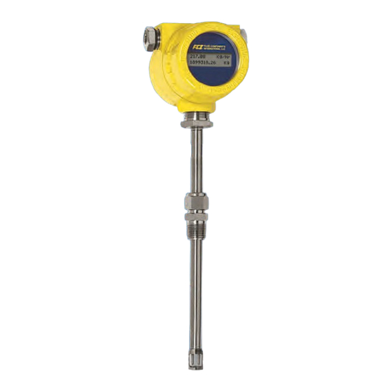
The ST51A is an insertion type flow meter for line sizes ranging from 2″ to 24″ [51 to 610 mm]. The ST75A is an in-line type flow meter for line sizes ranging from ¼″ to 2″ [6 mm to 51 mm]. Both ST51A and ST75A/ST75AV flow meters provide direct mass flow measuring and measures flow rate, totalized flow and temperature. -
Page 10: Hardware - Model Descriptions
ST51A/ST75A/ST75AV Mass Flow Meters Hardware – Model Descriptions ST51A – Single point insertion element with flow and temperature process output ST75A – In-line element with flow and temperature process output ST75AV – Vortab In-line element with flow and temperature process output Optional Accessories Table 1 –... -
Page 11: Specifications
■ Flow Element Temp Range ATEX/IECEx: II 2 G Ex db IIC T6...T1 Gb ST51A stainless steel ferrule: 0 °F to 350 °F [-18 °C to 177 °C] II 2 D Ex tb IIIC T85°C...T300°C Db; IP66/IP67 ST75A: 0 °F to 250 °F [-18 °C to 121 °C] Ta = -40°C to +65°C... - Page 12 GENERAL ST51A/ST75A/ST75AV Mass Flow Meters Flow Transmitter ■ Installation and Mounting ST51A – Integral with sensor element or remote mountable with ■ Enclosure interconnecting cable length of: 10′ [3 m), 25′ [7,6 m], 50′ [15 m], Rating: NEMA 4X [IP67] 100' [30 m] or custom length.
-
Page 13: Installation
Serial Number The ST51A, ST75A and ST75AV (Vortab) flow meters can be specified with integral or remote electronics. The flow element has a serial number etched into the side of the extension pipe (ST51A) or HEX (ST75A/ST75AV) as shown in Figure 1 below. -
Page 14: Figure 2 - Serial Number Location On Interface Board (Ac Version Shown) With Blind Cover Removed
Figure 2 – Serial Number Location on Interface Board (AC Version Shown) with Blind Cover Removed FLOW DIRECTION MARK POINTS TO FLOW DIRECTION REFERENCE/ORIENTATION FLAT PARALLEL TO FLOW DIRECTION THERMOWELLS PERPENDICULAR TO FLOW DIRECTION 90° C01159-1-1 Figure 3 – ST51A Flow Arrow Alignment Fluid Components International LLC... -
Page 15: Recommended Straight Run
Compression Fitting Mounting The ST51A is available with both Teflon compression fitting ferrules and metal ferrules. While the Teflon ferrule can be readjusted, it has a lower process pressure rating and over-tightening may cause it to become stuck or damage the extension pipe. The metal ferrule version can only be tightened down once and becomes permanently positioned. -
Page 16: Figure 5 - Flow Element Installation, Compression Fitting St51A
The flow element is properly mounted when the tip of the flow element is located 0.50 inches (13 mm) past the pipe centerline. The scale etched on the side of the insertion pipe indicates the length to the tip of the flow element. Follow the steps below to install the ST51A flow element. -
Page 17: Retractable Packing Gland Mounting
DEPTH C01444-1-1 Figure 6 – Flow Element Installation, Retractable Packing Gland ST51A Mark the insertion pipe at the calculated insertion depth. Ball Valve Applications Only: If a ball valve is required, install the ball valve to the process mounting coupling. Close the ball valve to prevent the process media from leaking out when installing the packing gland with the process line pressurized. -
Page 18: Retraction/Removal Procedure
INSTALLATION ST51A/ST75A/ST75AV Mass Flow Meters Retraction/Removal Procedure Loosen the socket head cap screw on the side of the locking collar. See Figure 7 below. Caution: For applications where the process media is pressurized to greater than 232 psig [16 bar(g)] make sure to first depressurize the process line before retracting the flow element. -
Page 19: Installing St75A/St75Av Flow Element
ST51A/ST75A/ST75AV Mass Flow Meters INSTALLATION Installing ST75A/ST75AV Flow Element Caution: The element is shipped already installed in the tee oriented for inline installation. Do not remove the sensing element from the tee during installation as performance can be affected. The ST75A/ST75AV is available in pipe tee configurations with NPT threads and tubing tees with a compression fitting to clamp down on concentric smooth surface tubing. -
Page 20: Installing The Remote Flow Meter System
2X ½" NPT PORT BRACKET ASSEMBLY LOCAL ENCLOSURE (BLIND) PROBE ASSEMBLY PIPE U LENGTH DIMENSION REMOTE CABLE (NPT CONFIGURATION SHOWN) C01314-1-1 Figure 9 – Typical Remote Flow Meter System (ST51A with ½" NPT Cable Port Shown) Fluid Components International LLC... -
Page 21: Remote Cable
ST51A/ST75A/ST75AV Mass Flow Meters INSTALLATION Remote Cable The remote cable connects the local enclosure’s flow element sensor to the transmitter electronics in the remote enclosure. The cable is available in standard lengths (10/25/50/100 ft. [3/7.6/15/30 m]) as well as custom length as specified in the order information sheet (OIS). -
Page 22: Local Enclosure
Depending on the configuration as specified by the order information sheet the ST51A local enclosure is supplied with a ½" or ¾” process connection, and the ST75A/ST75AV is supplied with a male NPT, female NPT or flanged process connection. -
Page 23: Remote Enclosure
ST51A/ST75A/ST75AV Mass Flow Meters INSTALLATION Install remote cable to local enclosure as shown in Figure 11. For NPT port units: Use an appropriate size reducer as applicable to the cable fitting used and the application. Ensure adequate cable service loop length before tightening the customer-supplied cable fitting. -
Page 24: Figure 13 - Remote Cable/Bracket Installation, Remote Enclosure
INSTALLATION ST51A/ST75A/ST75AV Mass Flow Meters Figure 13 – Remote Cable/Bracket Installation, Remote Enclosure CABLE CONNECTOR, LATCHED REMOTE CABLE, CONNECTOR END WIRES J4 HEADER (PLUG CABLE HERE) CIRCUIT BOARD NOTCH, FOR SENSOR WIRE ROUTING REMOTE ENCLOSURE (BLIND LID REMOVED) 2X 6-32 x ½" PAN HEAD... -
Page 25: Instrument Wiring
WIRING PORT, ½″ NPT or M20 BLIND LID (2 PLACES) SET SCREW BLIND LID (Remove to access wiring) EXTERNAL GROUND SCREW 10-32 x ¼″ SLOTTED HEX WASHER Figure 15 – ST51A/ST75A/ST75AV Wiring Access Fluid Components International LLC... -
Page 26: Accessing The Interface Board Connection Terminals
INSTALLATION ST51A/ST75A/ST75AV Mass Flow Meters ENCLOSURE BODY INTERNAL GROUND (BLIND LID REMOVED, SCREW, 10-32 x ¼″ AC VERSION SHOWN) SLOTTED HEX WASHER SIGNAL WIRING POWER WIRING C01162-1-2 Figure 16 – Recommended Wire Routing/Internal Ground Screw Accessing the Interface Board Connection Terminals Warning: Turn OFF instrument power source before wiring the instrument. -
Page 27: Interface Board Connections
ST51A/ST75A/ST75AV Mass Flow Meters INSTALLATION The above precautions are minimum requirements. The complete use of ESD precautions can be found in the U.S. Department of Defense Handbook 263. Interface Board Connections Power and signal connections are made at the interface board. Refer to Figure 17 below. -
Page 28: Figure 18 - Input Power Fuse Locations
INSTALLATION ST51A/ST75A/ST75AV Mass Flow Meters OWER EPLACEMENT Input power overload protection is provided by a 1.5 A slo-blo surface mount fuse installed in a fuse holder on the interface board. (To access this board see Accessing the Interface Board Connection Terminals, page 18.) Refer to... -
Page 29: Signal Connections
ST51A/ST75A/ST75AV Mass Flow Meters INSTALLATION Table 3 – Power and Signal Wiring Summary Connector Pin No. Function Description INT_HART+ Internal HART connection / 4-20 mA Ch. #1 (+) EXT_HART- External HART connection (-) J8, Signal INT_HART- Internal HART connection / 4-20 mA Ch. #1 (-) -
Page 30: Hart Connections
INSTALLATION ST51A/ST75A/ST75AV Mass Flow Meters HART Connections Connect the installation HART wiring to the appropriate J8 terminals depending on the application. ● Single Connection – The instrument supplies power to the loop and controls the current as well. For this application connect HART+ to J8-1 and HART- to J8-3. -
Page 31: Pulse Output And Alarm (Source/Sink)
ST51A/ST75A/ST75AV Mass Flow Meters INSTALLATION Pulse Output and Alarm (Source/Sink) Wire the source/sink outputs via the J7 terminals as required for your device (using sink or source output as appropriate) as shown in Figure 20 Figure 21 below. Either output can be used as a pulse output or a level (alarm) output. Observe the output power limits listed below. -
Page 32: Modbus Connections
INSTALLATION ST51A/ST75A/ST75AV Mass Flow Meters Modbus Connections The ST51A/ST75A/ST75AV Modbus interface is provided by interface board connector pins J7-1 [Data (A-)], J7-2 [Data (B+)], and J7-5 (Gnd/Common). Refer to Figure 17, page 19. Connect the instrument to a Modbus device/network using a 2-wire RS-485 connection... -
Page 33: Serial Interface Connector J9
ST51A/ST75A/ST75AV Mass Flow Meters INSTALLATION Serial Interface Connector J9 An RS-232 serial port is provided via a .100″ 2 x 3 header connector (J9) on the interface board (remove blind lid for access, see Accessing the Interface Board Connection Terminals, page 18). The J9 pinout is listed in Table 4 below. -
Page 34: Figure 24 - Block Diagram: Flow Meter Serial Port Connections, Fc88 And Computer
INSTALLATION ST51A/ST75A/ST75AV Mass Flow Meters Flow Meter to FC88 Connection RJ12 Flow Meter Cable FC88 Serial Port Adapter Calibrator (J9) (025859-01) Flow Meter to PC DB-25 Serial Port Connection RJ12 RJ12 to Flow Meter Cable DB-25 (F) PC DB-25 Serial Port... -
Page 35: Operation
Note: ST51A/ST75A units with a “Standard Calibration” (0 or A in Block 6 of the part number) are delivered in flow units of Standard Feet per Second (SFPS). Follow the steps in this section to customize the display and outputs if needed. -
Page 36: Main Menu
HART (3) – Enter “3” to operate the instrument in the HART mode. ● Config (4) – Enter “4” to select the configuration menu for ST51A/ST75A (1), Modbus (2), or HART (3). ● Update Firmware (5) – Reserved for factory-use only. -
Page 37: Z Menu: Configure Flow Units And 4-20 Ma Output Scaling
ST51A/ST75A/ST75AV Mass Flow Meters OPERATION Table 6 – Typical Serial Interface Top Level Commands for Flow Meter Configuration Command Name Description Normal Operation Mode Normal operating mode: All outputs are active. Flow Unit Set-up Set English/Metric flow units; set up pipe dimensions for volumetric units. -
Page 38: Changing Flow Units, Example
OPERATION ST51A/ST75A/ST75AV Mass Flow Meters Changing Flow Units, Example Table 7 below lists the steps for making a flow units change with these example parameters: SCFM Flow Units and 3-inch Schedule 40 round pipe size set-up: Table 7 – Flow Unit Example... -
Page 39: Figure 26 - V Menu Command Structure: Output Configuration Setup
ST51A/ST75A/ST75AV Mass Flow Meters OPERATION Menu Start “V” Command Select 4-20 mA Output Configuration Select 1: Select 2: Select 3: Select 4: 4-20mA #1: Flow 4-20mA #1: Flow 4-20mA #1: Temp 4-20mA #1: Temp 4-20mA #2: Temp 4-20mA #2: Flow... -
Page 40: 4-20 Ma Configuration
Source/Sink Output Configuration ST51A/ST75A/ST75AV instruments provide a source output and a sink output. Source: The instrument supplies the DC voltage and current for the level output/pulse (22 V, 25 mA max.) ●... -
Page 41: Serial Interface Command Reference
ST51A/ST75A/ST75AV Mass Flow Meters OPERATION ● Switchpoint0/Switchpoint1: The setpoint at which the level output activates when configured for Alarm function. The programmed setpoint is in the same units as the measured flow or temperature. For wiring details see Pulse Output and Alarm (Source/Sink, page 23. -
Page 42: Cli Commands
OPERATION ST51A/ST75A/ST75AV Mass Flow Meters CLI Commands Table 9 below summarizes the command line interface (CLI) commands accessible via the serial interface (computer/FC88). Note: When invoking a CLI write function separate the command mnemonic and the data value with a space. All Read and Write Functions are completed by pressing [ENTER]. - Page 43 ST51A/ST75A/ST75AV Mass Flow Meters OPERATION Command Mnemonic Command Function Command Description Data Type NAMUR Mode Enum DeltaR NAMUR Max Float O[1-7] Temp Comp, ACT_Toffst set Float Outmode Enum Switch Point0 Integer Switch Point1 Integer PCDeltaR Integer Pulse Factor Float Pulse Out...
-
Page 44: Hart Operation
The primary function of the instrument’s HART interface is to present process data via process data commands 1, 3 and 9. The ST51A/ST75A/ST75AV does not implement the HART Burst mode. A HART master that supports HART 7.0 and higher is required. If using a HART communicator, a unit that supports HART 7.0 or higher is required (i.e. -
Page 45: Eddl Files
ST51A/ST75A/ST75AV Mass Flow Meters OPERATION Table 11 below summarizes the instrument’s FieldComm Group device registration information. Table 11 – ST51A/ST75A/ST75AV HART Device Registration Information Product Name Product Type HART Version Mfgr. ID Device Type Dev. Revision FCI ST51A/ST75A Flow 0x00A6... - Page 46 Plenum or pipe size, enable or disable the Totalizer, review and change device information, reset the operation of the ST51A/ST75A/ST75AV to the factory settings, review and change PV Setup and review and change K Factors. Engineering Units Information...
- Page 47 ST51A/ST75A/ST75AV Mass Flow Meters OPERATION Totalizer The ST51A/ST75A/ST75AV Totalizer function lets you turn the totalizer ON or OFF. Factory Reset WARNING – The factory Reset command re-loads the configuration and calibration parameters that were loaded into the instrument during the original calibration and setup. Any changes made to the configuration of calibration parameters will be lost when the Factory Reset command is executed.
-
Page 48: Hart Command List Reference
ST51A/ST75A/ST75AV HART Universal Commands The ST51A/ST75A/ST75AV HART supports Universal Commands 0 through 22 and 38 and 48. Commands 4 and 5 are reserved under Universal Command Specification Rev. 7.1 (HCF_SPEC-127, Revision 7.1) and not implemented in this specification. There is no HART command 10. - Page 49 ST51A/ST75A/ST75AV Mass Flow Meters OPERATION Command 3: Read Dynamic Variable (Flow) and Loop Current Byte Format Description Request Data Bytes None Response Data Bytes 0–3 Float PV Loop Current: 4-20 mA Enum PV HART Unit Code, Flow 5–8 Float PV Flow Value...
- Page 50 OPERATION ST51A/ST75A/ST75AV Mass Flow Meters Command 9: Read Device Variables with Status Byte Format Description Request Data Bytes Unsigned-8 Slot 0: Device Variable Code Unsigned-8 Slot 1: Device Variable Code Unsigned-8 Slot 2: Device Variable Code Unsigned-8 Slot 3: Device Variable Code...
- Page 51 ST51A/ST75A/ST75AV Mass Flow Meters OPERATION Command 11: Read Unique Identifier Associated with Tag Byte Format Description Request Data Bytes 0–5 Packed Tag, Packed ASCII Response Data Bytes Unsigned-8 1–2 Enum Expanded Device Type Unsigned-8 Minimum number of preambles from master to slave...
- Page 52 OPERATION ST51A/ST75A/ST75AV Mass Flow Meters Command 15: Read Device Information Byte Format Description Request Data Bytes None Response Data Bytes Enum Flow Alarm Selection Code Enum Flow Transfer Function Code (not supported) Enum Flow Upper and Lower Range Value Units Code 3–6...
- Page 53 ST51A/ST75A/ST75AV Mass Flow Meters OPERATION Command 21: Read Unique Identifier Associated with Long Tag Byte Format Description Request Data Bytes 0–31 Latin-1 Long Tag Response Data Bytes Unsigned-8 1–2 Enum Expanded Device Type Unsigned-8 Minimum Number Of Preambles From Master to Slave...
- Page 54 OPERATION ST51A/ST75A/ST75AV Mass Flow Meters Command 48: Read Additional Device Status Byte Format Description Request Data Bytes 0–5 Bits Device-Specific Status (only first 2 bytes used, see page additional info) Bits Extended Device Status. Normally “0”; set to “1” (0x01) if maintenance is required.
-
Page 55: St51A/St75A/St75Av Hart Common Practice Commands
ST51A/ST75A/ST75AV Mass Flow Meters OPERATION ST51A/ST75A/ST75AV HART Common Practice Commands The ST51A/ST75A/ST75AV supports Common Practice commands 35, 40, 42, 44, 45, 46, 50 and 51. Table 13 below summarizes the instrument’s HART Common Practice command set and the data associated with each command. - Page 56 OPERATION ST51A/ST75A/ST75AV Mass Flow Meters Command 50: Read Dynamic Variable Assignments Byte Format Description Request Data Bytes None Response Data Bytes Unsigned-8 Device Variable assigned to the primary variable. Unsigned-8 Device Variable assigned to the secondary variable. Unsigned-8 Device Variable assigned to the tertiary variable.
-
Page 57: St51A/St75A/St75Av Hart Device Specific Commands
ST51A/ST75A/ST75AV HART Device Specific Commands In the HART protocol all commands defined as Manufacturer Specific, or Device Specific start at command 128. Use the device specific commands to setup and configure the ST51A/ST75A/ST75AV instrument via HART. Table 14 below summarizes the instrument’s HART Device Specific command set and the data associated with each command. - Page 58 OPERATION ST51A/ST75A/ST75AV Mass Flow Meters Command 146: Write Customer Flow Units Byte Format Description Request Data Bytes Unsigned-8 Units Code for Flow Response Data Bytes Unsigned-8 Units Code for Flow Response Codes: Table 16, page 53, for response code list.
- Page 59 ST51A/ST75A/ST75AV Mass Flow Meters OPERATION Command 155: Read KFactors Byte Format Description Request Data Bytes None Response Data Bytes 0–3 Float KFactor1 4–7 Float KFactor2 8–11 Float KFactor3 12–15 Float KFactor4 Response Codes: Table 16, page 53, for response code list.
-
Page 60: Hart Command Bit Assignments
OPERATION ST51A/ST75A/ST75AV Mass Flow Meters Command 163: Trim DAC Zero – Measured Current Chan #2 (in mA) Byte Format Description Request Data Bytes 0–3 Float Ext. Measured Current Ch. #2 Level (mA units) Response Data Bytes 0–3 Float Actual Measured Current Ch. #2 Level (mA units) -
Page 61: Table 15 - Command Status Bytes, Bit Assignments
ST51A/ST75A/ST75AV Mass Flow Meters OPERATION Table 15 – Command Status Bytes, Bit Assignments Error/Status Description Byte Communication Error Response Code (No Comm Error) Reserved – Bit cleared to zero. Buffer Overflow – The message was too long for the received buffer of the device. -
Page 62: Command 48, Additional Device Status Bytes
OPERATION ST51A/ST75A/ST75AV Mass Flow Meters Command 48, Additional Device Status Bytes Table 17 below summarizes the Command 48 Additional Device Status bytes. This is a 6-byte field of which only the first 2 bytes (bytes 0 and 1) are used by the instrument. The remaining bytes (2–5) are unused/reserved. A status bit is cleared (0) for no error. A status bit is set (1) when an error (or condition) is detected. -
Page 63: Hart Engineering Units Codes
ST51A/ST75A/ST75AV Mass Flow Meters OPERATION HART Engineering Units Codes Table 18 below summarizes the HART codes used to represent the instrument’s engineering units. Table 18 – HART Engineering Units Codes Units Type HART Code Unit Description degrees Celsius Temperature degrees Fahrenheit... -
Page 64: Modbus Operation
RTU and ASCII message coding. The ST51A/ST75A/ST75AV offers the process variable parameters (value) in floating point form, which are organized as single or double precision floating point registers. -
Page 65: St51A/St75A/St75Av Modbus Commands
(page 64) for Modbus register information and engineering unit codes, respectively. ST51A/ST75A/ST75AV Process Data Registers Two data type registers are set up in the ST51A/ST75A/ST75AV to access the process data. One uses integer data registers (4000) and the other uses the Daniel extension data registers (5000). -
Page 66: Totalizer Register Description
Register 5103 offers the flow Totalizer as a single precision floating point value in the Modbus Daniel extension protocol. Registers 4105 and 4106 offer the flow totalizer as a single precision floating point value in the standard Modbus register form. Table 20 – ST51A/ST75A/ST75AV Modbus Process Data Process Variable Values – Daniel Extension... -
Page 67: St51A/St75A/St75Av Modbus Service Registers
Read Examples of Totalizer Service Register Access using ModScan32 The ST51A Modbus supports enable and reset registers. Using any Modbus master/tester software such as ModScan32 or equivalent, the user can set parameters. ModScan32 is a Windows-based utility by WinTECH Software that lets a PC operate as a Modbus master device for testing Modbus systems. - Page 68 After entering the appropriate connection details the ModScan32 master then attaches itself to the Modbus device (ST51A/ST75A/ST75AV) as shown in figure at right. The register values display in the bottom, gray part of the program’s child window.
-
Page 69: Resetting The Totalizer Value
ST51A/ST75A/ST75AV Mass Flow Meters OPERATION Resetting the Totalizer Value ● Referring to Checking the Totalizer Value above, repeat step 1, but specify register #4027 instead (Length = 1). ● Repeat step 2 above (skip if already connected and configured). ●... -
Page 70: Checking K Factor Values
OPERATION ST51A/ST75A/ST75AV Mass Flow Meters Checking K Factor Values ● Referring to Checking the Totalizer Value above, repeat step 1, but specify register #41xx instead (i.e., K Factor registers #4107 through #4114). In this case, specify Length as “2” to check an MS/LS pair (i.e., 4107, 4109, 4111, or 4113). - Page 71 ST51A/ST75A/ST75AV Mass Flow Meters OPERATION Double click on the LS register #4108 line (see figure at right). In the resulting Write Register dialog, enter “999A” in the window’s value field, and then click Update. ENTER VALUE DOUBLE CLICK Verify that the upper 8 bits are programmed...
-
Page 72: Modbus Engineering Units Codes Table
OPERATION ST51A/ST75A/ST75AV Mass Flow Meters Modbus Engineering Units Codes Table Table 22 – Modbus Engineering Units Codes Units Type Modbus Code Unit Description degrees Celsius Temperature degrees Fahrenheit Standard Cubic Feet per Minute (SCFM) Standard Cubic Feet per Hour Normal Cubic Meters per Minute... -
Page 73: Maintenance
Flow Element Assembly Remove the flow element (insertion type, ST51A) or instrument/tee assembly (inline type, ST75A/ST75AV) for inspection based on historical evidence of debris, foreign matter or scale build-up, or plant shutdown schedules. Check for corrosion, stress cracking and build- up of oxides, salts or foreign substances. - Page 74 MAINTENANCE ST51A/ST75A/ST75AV Mass Flow Meters This Page Intentionally Left Blank Fluid Components International LLC...
-
Page 75: Troubleshooting
ST51A/ST75A/ST75AV Mass Flow Meters TROUBLESHOOTING TROUBLESHOOTING Application Verification After verifying that the flow meter is functioning, review the application parameters below to verify the calibration matches the process media. Equipment Needed ● Flow Instrument Calibration Data ● Process Parameters and Limits Check Serial Numbers Verify that the serial number of the flow element and the flow transmitter electronics are the same. -
Page 76: Verifying Calibration Parameters (Diagnostics)
TROUBLESHOOTING ST51A/ST75A/ST75AV Mass Flow Meters Verifying Calibration Parameters (Diagnostics) The instrument uses a set of predetermined calibration parameters to process flow signals. Most of these parameters typically do not change. A Delta R Data Sheet, provided with the instrument, contains the factory-set parameters. To verify that these parameters have not changed, complete the following: Identify the instrument’s Delta R Data Sheet via its serial number. -
Page 77: Hardware Verification
ST51A/ST75A/ST75AV Mass Flow Meters TROUBLESHOOTING Hardware Verification Equipment Required: ● Digital Multimeter (DMM) Fuse Check Verify that fuse F1, located on the interface board, is in normal working condition. Refer to Power Fuse Replacement, page for details on fuse access/location. Check the fuse for continuity. If fuse reads open, replace it with Littelfuse 454 Series fuse, part no. 045401.5. -
Page 78: Transmitter Circuit Calibration Check (Delta R Verification)
TROUBLESHOOTING ST51A/ST75A/ST75AV Mass Flow Meters Transmitter Circuit Calibration Check (Delta R Verification) References ● Delta R Data Sheet Equipment ● Serial console connection to instrument via FC88 or PC (see Instrument Configuration and Setup Using the Service Port (RS-232), page 27) ●... -
Page 79: Figure 29 - Transmitter Circuit Calibration Diagram
ST51A/ST75A/ST75AV Mass Flow Meters TROUBLESHOOTING ACTIVE BANAN A PLUG JUMPER, TYP. 4-IN LENGTH, 18 AWG OR BETTER (LOWER NUMBER) GREEN (DISCONNECTED) J4 SENSOR CONNECTOR To J4 REFERENCE NOTCH FOR PLUG KEY PIN 1 NORMALIZATION CABLE FCI P/N 022610-0x HTR EXC+... - Page 80 TROUBLESHOOTING ST51A/ST75A/ST75AV Mass Flow Meters This Page Intentionally Left Blank Fluid Components International LLC...
-
Page 81: Appendix Adrawings
ST51A/ST75A/ST75AV Mass Flow Meters APPENDIX A – DRAWINGS APPENDIX A DRAWINGS This appendix contains ST51A/ST75A/ST75AV technical drawings, which are summarized in Table 25 below. Table 25 – Appendix A, List of Drawings Dwg. No. Dwg. Type Page No. Description C01210-1-1 Exploded Assy. -
Page 82: Figure 30 - Basic Instrument Assembly: St51A, St75A And St75Av
APPENDIX A – DRAWINGS ST51A/ST75A/ST75AV Mass Flow Meters Figure 30 – Basic Instrument Assembly: ST51A, ST75A and ST75AV Fluid Components International LLC... - Page 83 ST51A/ST75A/ST75AV Mass Flow Meters APPENDIX A – DRAWINGS Fluid Components International LLC...
- Page 84 APPENDIX A – DRAWINGS ST51A/ST75A/ST75AV Mass Flow Meters Fluid Components International LLC...
- Page 85 ST51A/ST75A/ST75AV Mass Flow Meters APPENDIX A – DRAWINGS Fluid Components International LLC...
- Page 86 APPENDIX A – DRAWINGS ST51A/ST75A/ST75AV Mass Flow Meters Fluid Components International LLC...
- Page 87 ST51A/ST75A/ST75AV Mass Flow Meters APPENDIX A – DRAWINGS Fluid Components International LLC...
- Page 88 APPENDIX A – DRAWINGS ST51A/ST75A/ST75AV Mass Flow Meters Fluid Components International LLC...
- Page 89 ST51A/ST75A/ST75AV Mass Flow Meters APPENDIX A – DRAWINGS Fluid Components International LLC...
- Page 90 APPENDIX A – DRAWINGS ST51A/ST75A/ST75AV Mass Flow Meters Fluid Components International LLC...
- Page 91 ST51A/ST75A/ST75AV Mass Flow Meters APPENDIX A – DRAWINGS Fluid Components International LLC...
- Page 92 APPENDIX A – DRAWINGS ST51A/ST75A/ST75AV Mass Flow Meters Fluid Components International LLC...
- Page 93 ST51A/ST75A/ST75AV Mass Flow Meters APPENDIX A – DRAWINGS Fluid Components International LLC...
- Page 94 APPENDIX A – DRAWINGS ST51A/ST75A/ST75AV Mass Flow Meters Fluid Components International LLC...
- Page 95 ST51A/ST75A/ST75AV Mass Flow Meters APPENDIX A – DRAWINGS Fluid Components International LLC...
- Page 96 APPENDIX A – DRAWINGS ST51A/ST75A/ST75AV Mass Flow Meters Fluid Components International LLC...
- Page 97 ST51A/ST75A/ST75AV Mass Flow Meters APPENDIX A – DRAWINGS Fluid Components International LLC...
- Page 98 APPENDIX A – DRAWINGS ST51A/ST75A/ST75AV Mass Flow Meters This Page Intentionally Left Blank Fluid Components International LLC...
-
Page 99: Appendix Bglossary
ST51A/ST75A/ST75AV Mass Flow Meters APPENDIX B – GLOSSARY APPENDIX B GLOSSARY Abbreviations Delta-R (ΔR) Resistance differential Delta-T (ΔT) Temperature differential Digital Multimeter Fluid Components International Heater Liquid Crystal Display Light Emitting Diode Ordering Information Sheet Repair Authorization Resistance Temperature Detector... - Page 100 APPENDIX B – GLOSSARY ST51A/ST75A/ST75AV Mass Flow Meters This Page Intentionally Left Blank Fluid Components International LLC...
-
Page 101: Appendix Capproval Information
ST51A/ST75A/ST75AV Mass Flow Meters APPENDIX C – APPROVAL INFORMATION APPENDIX C APPROVAL INFORMATION EU Information Fluid Components International LLC... -
Page 102: Specific Conditions Of Use Per Fm16Atex0008X
APPENDIX C – APPROVAL INFORMATION ST51A/ST75A/ST75AV Mass Flow Meters Specific Conditions of Use per FM16ATEX0008X The ambient temperature range and applicable temperature class of the sensor probe is based on the maximum process temperature for the particular application as follows; T6…T1 for T of -40 °C to +65 and T... -
Page 103: Iec Information
ST51A/ST75A/ST75AV Mass Flow Meters APPENDIX C – APPROVAL INFORMATION IEC Information Fluid Components International LLC... - Page 104 APPENDIX C – APPROVAL INFORMATION ST51A/ST75A/ST75AV Mass Flow Meters Safety Instructions for the use o f the ST51A/ST75A/ST75AV flow meter in Hazardous Areas Approval FM16ATEX0008X/IECEX FMG 16.0009X: Category II 2 G for Gas protection Ex db IIC T6...T1 Gb Category II 2 D for Dust protection Ex tb IIIC T85°C...T300°C Db; IP66/IP67 The ST51/75 series consist of a sensing element and associated integral or remote mounted electronics mounted in a type “d”...
- Page 105 English - Safety instructions These safety instructions are valid for the Fluid Components, ST51A/75A/75AV flow meter to the EC type approval certificate no FM16ATEX0008X/IECEX FMG 16.0009X (certificate number on the type label) for use in potentially explosive atmospheres in Category II 2 GD.
- Page 106 Consignes de sécurité Ces consignes de sécurité sont valables pour le modèle ST51A/75A/75AV de la société Fluid Components (FCI) conforme au certificat d’épreuves de type FM16ATEX0008X/IECEX FMG 16.0009X (numéro du certificat sur l’étiquette signalétique) conçu pour les applications dans lesquelles un matériel de la catégorie II2GD est nécessaire.
- Page 107 Español - Instrucciones de seguridad Estas indicaciones de seguridad son de aplicación para el modelo ST51A/75A/75AV de Fluid Components, según la certificación CE de modelo Nº FM16ATEX0008X/IECEX FMG 16.0009X para aplicaciones en atmósferas potencialmente explosivas según la categoría II 2 GD (el número decertificación se indica sobre la placa informativa del equipo).
- Page 108 APPENDIX C – APPROVAL INFORMATION ST51A/ST75A/ST75AV Mass Flow Meters This Page Intentionally Left Blank Fluid Components International LLC...
-
Page 109: Appendix Dcustomer Service
ST51A/ST75A/ST75AV Mass Flow Meters APPENDIX D – CUSTOMER SERVICE APPENDIX D CUSTOMER SERVICE Customer Service/Technical Support FCI provides full in-house technical support. Additional technical representation is also provided by FCI field representatives. Before contacting a field or in-house representative, perform the troubleshooting techniques outlined in this document. -
Page 110: Field Service Procedures
APPENDIX D – CUSTOMER SERVICE ST51A/ST75A/ST75AV Mass Flow Meters Field Service Procedures Contact an FCI field representative to request field service. A field service technician is dispatched to the site from either the FCI factory or one of the FCI representative offices. After the work is com- plete, the technician completes a preliminary field service report at the customer site and leaves a copy with the customer. - Page 111 ST51A/ST75A/ST75AV Mass Flow Meters APPENDIX D – CUSTOMER SERVICE Fluid Components International LLC...
- Page 112 APPENDIX D – CUSTOMER SERVICE ST51A/ST75A/ST75AV Mass Flow Meters Fluid Components International LLC...
- Page 113 ST51A/ST75A/ST75AV Mass Flow Meters APPENDIX D – CUSTOMER SERVICE WARRANTIES Goods furnished by the Seller are to be within the limits and of the sizes published by the Seller and subject to the Seller’s standard tolerances for variations. All items made by the Seller are inspected before shipment, and should any of said items prove defective...
- Page 114 ST51A/ST75A/ST75AV Mass Flow Meters Visit FCI on the Worldwide Web: www.fluidcomponents.com FCI World Headquarters 1755 La Costa Meadows Drive | San Marcos, California 92078 USA | Phone: 760-744-6950 Toll Free (US): 800-854-1993 Fax: 760-736-6250 FCI Europe Persephonestraat 3-01 | 5047 TT Tilburg, The Netherlands | Phone: 31-13-5159989 Fax: 31-13-5799036 FCI Measurement and Control Technology (Beijing) Co., LTD | www.fluidcomponents.cn...
Need help?
Do you have a question about the ST51A and is the answer not in the manual?
Questions and answers