Sign In
Upload
Manuals
Brands
Fluid Components Intl Manuals
Measuring Instruments
ST51A
Fluid Components Intl ST51A Flow Meter Manuals
Manuals and User Guides for Fluid Components Intl ST51A Flow Meter. We have
1
Fluid Components Intl ST51A Flow Meter manual available for free PDF download: Installation, Operation & Maintenance Instruction Manual
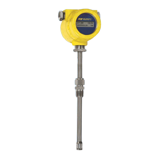
Fluid Components Intl ST51A Installation, Operation & Maintenance Instruction Manual (114 pages)
Mass Flow Meters
Brand:
Fluid Components Intl
| Category:
Measuring Instruments
| Size: 5.8 MB
Table of Contents
Table of Contents
3
List of Figures
7
1 General
9
Product Description
9
Theory of Operation
9
Safety Instructions
9
Order Verification
9
Hardware - Model Descriptions
10
Optional Accessories
10
Table 1 - Optional Accessories
10
Specifications
11
2 Installation
13
Instrument Identification and Outline Dimensions
13
Pre-Installation
13
Serial Number
13
Flow Direction Alignment
13
Figure 1 - Probe Serial Number, Reference Flat and Flow Direction Mark
13
Figure 2 - Serial Number Location on Interface Board (AC Version Shown) with Blind Cover Removed
14
Figure 3 - ST51A Flow Arrow Alignment
14
Recommended Straight Run
15
Installing ST51A Flow Element
15
Compression Fitting Mounting
15
Figure 4 - Recommended Straight Run (ST75A Shown)
15
Figure 5 - Flow Element Installation, Compression Fitting ST51A
16
Table 2 - Compression Fitting Material
16
Retractable Packing Gland Mounting
17
Figure 6 - Flow Element Installation, Retractable Packing Gland ST51A
17
Figure 7 - Retractable Packing Gland Locking Collar Detail
18
Retraction/Removal Procedure
18
Installing ST75A/ST75AV Flow Element
19
Pipe Tee Installation
19
Tube Tee Installation
19
NPT Flow Tube Installation
19
Flanged Installation
19
Re-Positioning the Display
19
Installing the Remote Flow Meter System
20
Figure 8 - Display Re-Positioning
20
Figure 9 - Typical Remote Flow Meter System (ST51A with ½" NPT Cable Port Shown)
20
Figure 10 - Remote Cable, Interconnecting
21
Remote Cable
21
Figure 11 - Remote Cable Installation, Local Enclosure
22
Figure 12 - Local Enclosure Remote Cable Wiring
22
Local Enclosure
22
Remote Enclosure
23
Figure 13 - Remote Cable/Bracket Installation, Remote Enclosure
24
Figure 14 - Remote Enclosure Interface Board Connector J4 Detail (AC Version Shown)
24
Instrument Wiring
25
Figure 15 - ST51A/ST75A/ST75AV Wiring Access
25
Accessing the Interface Board Connection Terminals
26
ESD Precautions
26
Figure 16 - Recommended Wire Routing/Internal Ground Screw
26
Interface Board Connections
27
Power Connections
27
Figure 17 - Power and Signal Wiring Terminals
27
Figure 18 - Input Power Fuse Locations
28
Signal Connections
29
4-20 Ma Analog Outputs
29
Table 3 - Power and Signal Wiring Summary
29
HART Connections
30
Figure 19 - Single Connection and Multidrop HART Setups
30
Pulse Output and Alarm (Source/Sink)
31
Figure 20 - Sink Output
31
Figure 21 - Source Output
31
Modbus Connections
32
Figure 22 - Modbus Wiring
32
Figure 23 - Serial Cable Adapter 025859-01 Plugged into Flow Meter J9 Header
33
Serial Interface Connector J9
33
Table 4 - Serial Port J9 Pinout
33
Figure 24 - Block Diagram: Flow Meter Serial Port Connections, FC88 and Computer
34
3 Operation
35
Overview
35
Instrument Configuration and Setup Using the Service Port (RS-232)
35
Table 5 - Serial (COM) Port Configuration
35
Main Menu
36
Secondary Commands: CLI
36
Top Level Menu Commands
36
Start-Up and Commissioning
36
Z Menu: Configure Flow Units and 4-20 Ma Output Scaling
37
Figure 25 - Z Menu Command Structure: Units and Scaling Setup
37
Table 6 - Typical Serial Interface Top Level Commands for Flow Meter Configuration
37
Changing Flow Units, Example
38
Menu: Configure Outputs (4-20 Ma and Source/Sink Outputs)
38
Table 7 - Flow Unit Example
38
Figure 26 - V Menu Command Structure: Output Configuration Setup
39
4-20 Ma Configuration
40
Flow/Temperature Assignment
40
NAMUR Mode
40
HART Damping Value
40
Source/Sink Output Configuration
40
Source/Sink Output Functions
40
Source/Sink Output Programming Parameters
40
Serial Interface Command Reference
41
Top Level Menu Commands
41
Table 8 - Top Level Menu Commands
41
CLI Commands
42
Table 9 - List of CLI Commands
42
HART Operation
44
Process Data Operation
44
ST51A/ST75A/ST75AV HART Process Data Organization
44
ST51A/ST75A/ST75AV Process Variable Slots
44
Primary Variable Classifications
44
Device Description Files
44
Table 10 - ST51A/ST75A/ST75AV HART Process Variables
44
EDDL Files
45
Loading the DD Files to the 475 Field Communicator
45
Service Data Operation
45
Figure 27 - Field Communicator Easy Upgrade Utility, Import DD
45
Table 11 - ST51A/ST75A/ST75AV HART Device Registration Information
45
HART Command List Reference
48
ST51A/ST75A/ST75AV HART Universal Commands
48
Table 12 - HART Universal Commands
48
ST51A/ST75A/ST75AV HART Common Practice Commands
55
Table 13 - HART Common Practice Commands
55
ST51A/ST75A/ST75AV HART Device Specific Commands
57
Table 14 - HART Device Specific Commands
57
HART Command Bit Assignments
60
Command Status Bytes
60
Table 15 - Command Status Bytes, Bit Assignments
61
Table 16 - Command-Specific Response Codes
61
Command 48, Additional Device Status Bytes
62
Table 17 - Command 48, Additional Device Status Bytes Bit Assignments
62
HART Engineering Units Codes
63
Table 18 - HART Engineering Units Codes
63
Modbus Operation
64
Setting up the ST51A/ST75A/ST75AV for Modbus Operation
64
ST51A/ST75A/ST75AV Modbus Commands
65
ST51A/ST75A/ST75AV Process Data Registers
65
Table 19 - ST51A/ST75A/ST75AV Modbus Function Codes
65
Totalizer Register Description
66
Table 20 - ST51A/ST75A/ST75AV Modbus Process Data
66
ST51A/ST75A/ST75AV Modbus Service Registers
67
Examples of Totalizer Service Register Access Using Modscan32
67
Checking the Totalizer Value
67
Table 21 -Modbus Service Data
67
Resetting the Totalizer Value
69
Starting/Stopping the Totalizer Count
69
Checking K Factor Values
70
Changing/Setting K Factor Values
70
Modbus Engineering Units Codes Table
72
Modbus Device Status Code Table
72
Table 22 - Modbus Engineering Units Codes
72
Table 23 - Device Status Code Bit Assignments, Register #4025
72
4 Maintenance
73
Calibration
73
Electrical Connections
73
Remote Enclosure
73
Electrical Wiring
73
Flow Element Connections
73
Flow Element Assembly
73
5 Troubleshooting
75
Application Verification
75
Equipment Needed
75
Check Serial Numbers
75
Check the Instrument Installation
75
Check for Moisture
75
Check Application Design Requirements
75
Verify Standard Versus Actual Process Conditions
75
Verifying Calibration Parameters (Diagnostics)
76
Table 24 - Diagnostic Test Sequence
76
Hardware Verification
77
Fuse Check
77
Sensor Check
77
Figure 28 - Reference and Active Sensor Resistance Check (AC Version Shown)
77
Transmitter Circuit Calibration Check (Delta R Verification)
78
References
78
Equipment
78
Procedure
78
Figure 29 - Transmitter Circuit Calibration Diagram
79
Appendix Adrawings
81
Table 25 - Appendix A, List of Drawings
81
Figure 30 - Basic Instrument Assembly: ST51A, ST75A and ST75AV
82
Appendix Bglossary
99
Abbreviations
99
Definitions
99
Appendix Capproval Information
101
EU Information
101
Specific Conditions of Use Per FM16ATEX0008X
102
IEC Information
103
Appendix Dcustomer Service
109
Customer Service/Technical Support
109
Warranty Repairs or Returns
109
Non-Warranty Repairs or Returns
109
Extended Warranty
109
Return to Stock Equipment
109
Field Service Procedures
110
Field Service Rates
110
Advertisement
Advertisement
Related Products
Fluid Components Intl ST75A
Fluid Components Intl ST75AV
Fluid Components Intl ST98
Fluid Components Intl AF Series
Fluid Components Intl AF88
Fluid Components Intl AF89
Fluid Components Intl FLT Series
Fluid Components Intl FLT93-C
Fluid Components Intl FLT93-F
Fluid Components Intl FLT93-L
Fluid Components Intl Categories
Measuring Instruments
More Fluid Components Intl Manuals
Login
Sign In
OR
Sign in with Facebook
Sign in with Google
Upload manual
Upload from disk
Upload from URL