Table of Contents
Advertisement
Quick Links
INSTALLATION, OPERATION AND
MAINTENANCE MANUAL
This document contains confidential technical data, including trade
secrets and proprietary information which are the property of Fluid
Components Intl (FCI).
Disclosure of this data to you is expressly conditioned upon your assent
that its use is limited to use within your company only (and does not
include manufacture or processing uses). Any other use is strictly
prohibited without the prior written consent of FCI.
Model ST98
Flowmeter
Firmware Revisions 2.XX
Doc. No. 06EN003291 Rev. A
US PATENTS PENDING
Notice of Proprietary Rights
© Copyright 1999 Fluid Components Intl
a limited liability company
All Rights Reserved
8 / 5 / 9 9 R E V . -
3 / 9 / 0 0 R E V . A
Advertisement
Table of Contents
Troubleshooting

Related Manuals for Fluid Components Intl ST98


Summary of Contents for Fluid Components Intl ST98
- Page 1 (and does not include manufacture or processing uses). Any other use is strictly prohibited without the prior written consent of FCI. © Copyright 1999 Fluid Components Intl a limited liability company All Rights Reserved 8 / 5 / 9 9 R E V .
- Page 2 COMPLETE CUSTOMER COMMITMENT. COMMITMENT TO QUALITY In keeping with the overall commitment of management and employees of Fluid Components Intl to Total Quality Management, the Technical Publications Department expresses its pledge and mission to you, our customer: “To support the creation and publication of world-class technical material which is technically accurate and...
- Page 3 1 (800) 854-1993 and follow the prerecorded instructions. A person from the Technical Support Staff will be paged and promptly return the call. Appendix C contains a detailed explanation of the FCI customer service policy on returns, adjustments, in-field or factory repair, in- or out-of-warranty. Model ST98 Flow Meter Doc. No. 06EN003291 Rev. A...
- Page 4 DESCRIPTION DATE AUTHOR ROY SANDERS 08/05/99 INITIAL RELEASE ROY SANDERS 03/01/00 See Change Bars. Major changes are due to new 2.xx Software and Revised circuit boards to Rev. A or Later. Doc. No. 06EN003291 Rev. A Model ST98 Flow Meter...
-
Page 5: Table Of Contents
General Function Check ...................... 5 - 1 Tools Needed - General Function Check - ..............5 - 1 NAMUR Fault Indicaton ....................5 - 1 Application Verification ...................... 5 - 3 Model ST98 Flow Meter Doc. No. 06EN003291 Rev. A... - Page 6 Figure 1-1. View of the Sensing Element ..................... 1 - 1 Figure 1-2. Cut-Away View of the In-Line Flow Element Tube ............1 - 2 Figure 2-1. Model ST98 Insertion Flow Element Showing Orientation ..........2 - 2 Figure 2-2. Model ST98 In-Line Butt Weld Mount ................2 - 4 Figure 2-3.
- Page 7 Table 5-4. Resistance Versus Wire Size ....................5 - 6 Table 5-5. Approximate Flow Element Voltages at 70°F ..............5 - 6 Table 5-6. Instrument Voltages ......................5 - 7 Model ST98 Flow Meter viii Doc. No. 06EN003291 Rev. A...
- Page 8 The following symbols are used throughout the manual to draw attention to items or procedures that require special notice or care. Caution: Warns of possible personal danger to those handling the equipment. Alert: May cause possible equipment damage. Note: Contains important information. Doc. No. 06EN003291 Rev. A Model ST98 Flow Meter...
-
Page 9: General Information
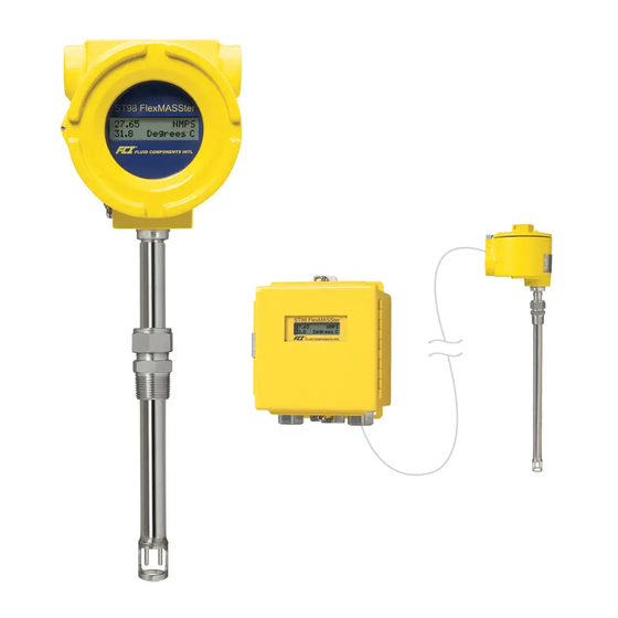
The ST98 flow transmitter accepts AC or DC input power and the output signal can be set for either a standard range current or voltage. A display is optional. An RS-232C serial I/O port provides setup, monitoring and troubleshooting access using either FCI’s model FC88 Programmer or a PC-compatible computer. -
Page 10: In-Line Sensing Element
NEMA7) and EEx d IIC and resists the effect of weather and corrosion. The dimensions are 4.68 X 4.82 inches (119 X 122 mm) and is cylindrical in nature. Model ST98 Flow Meter 1 - 2 Doc. No. 06EN003291 Rev. A... -
Page 11: Technical Specifications
-40 to 350°F (-40 to 177°C). Maximum. • Operating Pressure • Pending Approvals 0 to 250 psig [0 to 17 bar(g)]. (Derated with FM, CSA, CENELEC, CE Marking Teflon ferrule.) (EMC Directive 89/336/EEC) Doc. No. 06EN003291 Rev. A 1 - 3 Model ST98 Flow Meter... -
Page 12: Quick Start Menu (Abbreviated)
CHANGE IT?< REINITIALIZES SOFTWARE WITHOUT EXITS COMMAND RESET POWER DOWN PRESS [ENTER] AFTER EACH MENU SELECTION TO ACTIVATE COMMAND RESETS FC88 RE-CONFIGURE TO USE WITH EXITS COMMAND FC88 ST98 Model ST98 Flow Meter 1 - 4 Doc. No. 06EN003291 Rev. A... -
Page 13: Installation
The above precautions are minimum requirements to be used. The complete use of ESD precautions can be found in the U.S. Department of Defense Handbook 263. Doc. No. 06EN003291 Rev. A 2 - 1 Model ST98 Flow Meter... -
Page 14: Prepare Or Verify Flow Element Location
A flow direction arrow is etched on the in-line ST98 tube or pipe and should be pointing in the direction of flow. Failing to install the flow element correctly will reduce the accuracy of the flow meter. -
Page 15: Install Insertion Flow Element
0.50 inch (12.7 mm) from the U-Length. The process' flanged mating surface for the flow element should be high enough above the pipe for proper mounting of the flow element as follows: Measure the inside diameter Doc. No. 06EN003291 Rev. A 2 - 3 Model ST98 Flow Meter... -
Page 16: In-Line Mounting
Refer to ANSI B16.5 specifications. In-Line Mounting There are several different ways the in-line model ST98 instrument can be mounted into the process line. The different ways the flow element can be mounted are as follows: •... -
Page 17: Minimum Wire Size
8. For remote instruments only, (the flow element is in a separate enclosure from the electronics): Loosen the Allen head screw on the electronics cover. Unscrew the cover. Doc. No. 06EN003291 Rev. A 2 - 5 Model ST98 Flow Meter... -
Page 18: Figure 2-3. Circuit Board Placement
This is for the purpose of safety. 10. If a wire comes loose from the instrument during installation, refer to Chapter 5 - Troubleshooting for a complete instrument wiring diagram. Model ST98 Flow Meter 2 - 6 Doc. No. 06EN003291 Rev. A... -
Page 19: Carbon Steel Enclosure Installation
6. Attach the filter bead over the safety ground wire as shown in Figure 2-4 using 2 cable ties to secure the bead on the wire. The last cable tie should be about 3 inches from the end of the wire. Doc. No. 06EN003291 Rev. A 2 - 7 Model ST98 Flow Meter... -
Page 20: Remote Hardware Location
Table 2-1 for the minimum wire gauge to use. Wiring the In-Line Flow Element (Option) Electrically the in-line flow element is the same as the model ST98 insertion flow element. Wire the instrument using the local enclosure or remote enclosure and/or the pigtail wiring methods above. -
Page 21: Serial Communication
Figure 2-7. Wiring Diagram, DB-9 and DB25 PC Connectors FCI recommends using the ST98 PC Interface Kit P/N: 014108-01 to connect the flow transmitter to a personal computer. The Kit includes operation instructions and an adaptor for the RJ-12 to serial connection. Connect one end of the interface kit to the RJ-12 port and the other end to a DB pin connector. -
Page 22: Remote Enclosure Bracket Installation
The input power should not be turned on until the installation has been completed with all connections verified, power and signal connection board assembly screwed down and the instrument ready to operate. Be sure any external circuit breakers are on. Model ST98 Flow Meter 2 - 10 Doc. No. 06EN003291 Rev. A... -
Page 23: Operation
An FC88 is a hand held communicator that is plugged into the flow meter which controls the various functions of the ST98. Plug in the FC88 to P1 of the customer connection board. See Figure 2-4 for details. This instrument is convenient, compact, and obtains its operating power from the flow transmitter. It provides a keypad for operator input and a display for system output. -
Page 24: Figure 3-1. Menu Selections Chart
HIGH (90 mA) or LOW (75 mA) Balance or rebalance Flow Element Re-configure FC88 Unit Calibrate Display Reset the FC88 hand held to ST98 format Display A/D Delta-R and Ref-R data values Undefined Diagnostic Check out functional conditions of the unit... -
Page 25: Quick Start Menu
CHANGE IT?< REINITIALIZES SOFTWARE WITHOUT EXITS COMMAND RESET POWER DOWN PRESS [ENTER] AFTER EACH MENU SELECTION TO ACTIVATE COMMAND RESETS FC88 RE-CONFIGURE TO USE WITH EXITS COMMAND FC88 ST98 Doc. No. 06EN003291 Rev. A 3 - 3 Model ST98 Flow Meter... -
Page 26: Detailed Menu Description
[Enter] displays “Ch(6): xxxx” [Enter] displays “Ch(7): xxxx” [Enter] displays “Ch(0): xxxx” Note: Pressing [Q] [ENTER] at any time will exit this menu item and display “Input mode ?<”. Model ST98 Flow Meter 3 - 4 Doc. No. 06EN003291 Rev. A... - Page 27 Pressing [C] [ENTER] will display “d= xxxx R= xxxx”. The display is updated continuously. Note: Pressing [ENTER] at any time will exit this menu and display "Input mode?<" Doc. No. 06EN003291 Rev. A 3 - 5 Model ST98 Flow Meter...
- Page 28 Pressing the [Q] key at any time will exit the Diagnostics menu. The ST98 functional data in RAM is saved in the USER area of the Non-Volatile Memory (NVM). The user has the option to save user data to the USER Save area of NVM at any time.
- Page 29 Pressing [H] [ENTER] will display “Heater OFF!” or “Heater ON!” on line 1 depending on which state was last active. “Input mode ?<” is displayed on line 2. Doc. No. 06EN003291 Rev. A 3 - 7 Model ST98 Flow Meter...
- Page 30 ‘Y’ will display “c1 = xxxxxxx” followed by “Change it?>”. If ‘Y’ is pressed, a coefficient value must be entered or else the next coefficient will be displayed, etc. After coefficients are entered or ‘N’ or [Enter] is Model ST98 Flow Meter 3 - 8...
- Page 31 This is accomplished by monitoring the output currents while adjusting input to the DAC until the correct output values are reached. Both course and fine adjustment controls are available for calibration. Doc. No. 06EN003291 Rev. A 3 - 9 Model ST98 Flow Meter...
- Page 32 Sometimes it becomes necessary to initialize the instrument. (i.e. when entering new constants, troubleshooting, or when power interruption is not practical.) Example: Pressing [N] [ENTER] will display "Restart - Wait!" followed by the initialization display: "FCI ST98", "Initialization!", "Heater ON!", "Version x.xx" and "Scale = 1.00000". Finally, "Input mode<", is displayed.
- Page 33 ‘P’ until the FC88 has been reset to use 32 characters (two line display). COMMAND: Q. Undefined COMMAND: R. Delta-R, Ref-R, CB Temp, -8 V and +20 V Supply Doc. No. 06EN003291 Rev. A 3 - 11 Model ST98 Flow Meter...
- Page 34 The default units will not permit a totalized flow to be displayed. Example: T [ENTER] will display “53.0 SFPS” on line 1, and “70.8 Degrees F” on line 2 (example based on default units). Model ST98 Flow Meter 3 - 12 Doc. No. 06EN003291 Rev. A...
- Page 35 The instrument must be in one of the following flow units (SCFM, Lbs/Hr, NCMH, Kg/Hr) (see command Z) to display the totalized flow. Totalized flow can be reset to zero at any time or whenever power is interrupted. Doc. No. 06EN003291 Rev. A 3 - 13 Model ST98 Flow Meter...
- Page 36 The volume and mass flow units require specific line size dimensions. Typically, flow rate ranges are 100:1 but can be adjusted to 10:1 by entering a new full scale and/or zero level. In this mode, the instrument will not accept Model ST98 Flow Meter 3 - 14...
- Page 37 Press [Y] [ENTER] and enter a new value or else press [N] [ENTER] or [ENTER]. The next prompt is “Save ?<”. Press ‘Y’ and the new values are saved. The last prompt is “Input mode ?<”. Volume (Metric) Doc. No. 06EN003291 Rev. A 3 - 15 Model ST98 Flow Meter...
-
Page 38: Using Procomm Software
3. Set for COM1 or COM2, 9600 Baud, 8 Bit, 1 Stop Bit, and No Parity. Press OK. 4. Press the ENTER key to see the Input Mode? prompt. 5. Enter any of the ST98 single letter commands to execute a function. Model ST98 Flow Meter 3 - 16 Doc. -
Page 39: Maintenance
Any debris or residue build-up could cause inaccurate switching. Clean the flow element, as necessary, with a soft brush and available solvents (compatible with Stainless Steel). Doc. No. 06EN003291 Rev. A 4 - 1 Model ST98 Flow Meter... -
Page 40: Troubleshooting
T mode are prioritized in the order of where the problem will most likely be found. Example: Error codes are: "Sensor Error" "Overtemp Head" There is most likely a sensor element wiring problem that is creating an over temperature fault situation. Doc. No. 06EN003291 Rev. A 5 - 1 Model ST98 Flow Meter... -
Page 41: Table 5-1. Namur Fault Listing
ST98 (if present) to verify operation. Replace the cable display on the optional LCD display. between the ST98 and the FC88 if there is no operation. If no operation contact customer service. No fault indicated. Output mA or Verify the NAMUR option is activated [X] [ENTER]. -
Page 42: Application Verification
= Volumetric Flow Q = Standard Volumetric Flow = Actual Pressure = Actual Temperature = Standard Pressure T = Standard Temperature PSIA and °R are used for pressure and temperature units. Doc. No. 06EN003291 Rev. A 5 - 3 Model ST98 Flow Meter... -
Page 43: Verify The Calibration Parameters
The instrument uses a set of predetermined calibration parameters to process flow signals. Most of these parameters should not change. A data package located at the rear of this manual contains the “ST98 Delta R Data Sheet”. This contains the calibration ST98 parameters stored in the flow transmitter at the factory. To verify that these parameters have not changed, complete the following: 1. -
Page 44: Check The Hardware
ACT EXC ACT SEN HTR EXC REF EXC HTR RTN ACT EXC HTR EXC HTR RTN Figure 5-2. TS2 Connector Plug Figure 5-3. Terminal Block In Local Enclosure Doc. No. 06EN003291 Rev. A 5 - 5 Model ST98 Flow Meter... -
Page 45: Check The Flow Element Voltages
Cable resistance of the remote flow element will affect the TS2 voltage readings at the electronics enclosure. *Voltages varies with Temperature and Flow and the Sensor Heater Current Selection. **Voltage will vary with the process flow rate. Model ST98 Flow Meter 5 - 6 Doc. No. 06EN003291 Rev. A... -
Page 46: Verification Of The Electronics
5. Press [T] [ENTER] to view the normal operating mode. Adjust the active and reference decade boxes. Verify the parameters on the FC88 change. If the display changes, proceed to the next section. If the display is frozen the instrument is malfunctioning. Contact Customer Service. Doc. No. 06EN003291 Rev. A 5 - 7 Model ST98 Flow Meter... -
Page 47: Instrument Output Check
Remote Enclosure is NOT covered by product warranty. Spares FCI recommends one of each of the following should be kept as a spare: One identically set up ST98 Flow meter. Contact FCI for specific recommendations. Model ST98 Flow Meter 5 - 8 Doc. -
Page 48: Defective Parts
2. Before contacting the FCI representative, please be sure that all the applicable information is near so that a more effective, efficient and timely response may be provided. 3. Refer to Appendix C for specific Customer Service policy provisions. Doc. No. 06EN003291 Rev. A 5 - 9 Model ST98 Flow Meter... -
Page 49: Appendix A. Drawings
POWER SIDE SIDE 3/4 IN. NPT CONDUIT PORT COVER LOCK 4.00 [101.60] Ø4.80 9.31 [121.92] [236.47] Figure A-2. Remote Aluminum Double Ended Enclosure NEMA 4X and Hazardous Location Doc. No. 06EN003291 Rev. A A - 1 Model ST98 Flow Meter... - Page 50 FLUID COMPONENTS INTL APPENDIX A - DRAWINGS Figure A-3. Remote or Local Enclosure, Carbon Steel Model ST98 Flow Meter A - 2 Doc. No. 06EN003291 Rev. A...
-
Page 51: Figure A-4. 3/4 Inch Ferrule Npt Process Connection
APPENDIX A - DRAWINGS FLUID COMPONENTS INTL Figure A-4. 3/4 Inch Ferrule NPT Process Connection Figure A-5. 3/4 Inch Ferrule NPT With Flange Process Connection Figure A-6. In-Line Flanged Process Connection Doc. No. 06EN003291 Rev. A A - 3 Model ST98 Flow Meter... -
Page 52: Figure 2-5. Remote Wiring Diagram
ACT EXC 6 ACT EXC 6 HTR EXC 7 HTR EXC 7 HTR RTN 8 HTR RTN 8 USE 8 CONDUCTOR SHIELDED CABLE ONLY SHIELD Figure A-9. Remote Wiring Diagram Model ST98 Flow Meter A - 4 Doc. No. 06EN003291 Rev. A... -
Page 53: Figure A-10. Wiring Diagram Between Circuit Boards
OPTIONAL DISPLAY ASSEMBLY P2 RIBBON CABLE P2 RIBBON CABLE CONTROLLER BOARD P/N 017651 Figure A-11. Optional Display Ribbon Cable Connection Figure A-12. Remote Mounting Bracket (Hazardous Location Enclosure Only) Doc. No. 06EN003291 Rev. A A - 5 Model ST98 Flow Meter... - Page 54 921.424 1012.694 1103.272 1193.130 923.555 1014.808 1105.371 1195.210 925.685 1016.922 1107.468 1197.290 927.814 1019.036 1109.566 1199.370 929.944 1021.149 1111.663 1201.449 932.073 1023.262 1113.759 1203.528 934.201 1025.374 1115.855 1205.607 Model ST98 Flow Meter A - 6 Doc. No. 06EN003291 Rev. A...
- Page 55 1284.249 1372.363 1459.380 1545.080 1286.310 1374.400 1461.389 1547.056 1288.369 1376.436 1463.397 1549.030 1290.429 1378.472 1465.404 1551.004 1292.487 1380.507 1467.411 1552.977 1294.546 1382.541 1469.417 1554.948 1296.603 1384.575 1471.422 1556.919 Doc. No. 06EN003291 Rev. A A - 7 Model ST98 Flow Meter...
- Page 56 1596.151 1598.103 1600.054 1602.004 1603.953 1605.901 1607.848 1609.794 1611.739 1613.683 1615.626 1617.568 1619.509 1621.449 1623.388 1625.326 1627.263 1629.200 1631.135 1633.069 1635.002 1636.933 1638.864 1640.794 1642.723 1644.651 1646.577 1648.503 Model ST98 Flow Meter A - 8 Doc. No. 06EN003291 Rev. A...
-
Page 57: Appendix B. Glossary
RTD's when the heater is off. C. CALIBRATE DISPLAY Menu Function. d=xxx The display of Delta-R in the Calibrate Display menu. r=xxx The display or Ref-R in the Calibrate Display menu. Doc. No. 06EN003291 Rev. A B - 1 Model ST98 Flow Meter... - Page 58 Zero An adjustment that establishes at what flow rate the flow transmitter's output is at its minimum (4 mA, 0 VDC). 0.00 is for zero based Model ST98 Flow Meter B - 2 Doc. No. 06EN003291 Rev. A...
- Page 59 Enter # Entering a number (0-1000) will force the output to a corresponding level. Digital to Analog Converter number corresponds to output level. J. SERIAL NUMBER, CUSTOMER ORDER Doc. No. 06EN003291 Rev. A B - 3 Model ST98 Flow Meter...
- Page 60 Choosing xxxMD does not set any software flags. P. RECONFIGURE THE FC88 UNIT Menu Function. FC88 Reset Re-configures the FC88 so it will function properly in conjunction with the ST98. R. A/D CALIBRATE RESISTANCE Menu Function. A/D Delta-R The difference between the RTD resistances as used by the A/D converter.
- Page 61 This establishes at what flow rate the flow transmitter's output is at its minimum output. It is 0.00 for zero based applications. For non-zero based applications the zero is at minimum flow. Doc. No. 06EN003291 Rev. A B - 5 Model ST98 Flow Meter...
-
Page 62: Customer Service
FCI will invoice the customer for the charges that appear on the freight bill. Address the return equipment to: FLUID COMPONENTS INTL 1755 LA COSTA MEADOWS DRIVE SAN MARCOS, CA. 92069 ATTN: REPAIR DEPT. RA NUMBER: Probe protector Doc. No. 06EN003291 Rev. A C - 1 Model ST98 Flow Meter... - Page 63 Customers are charged for shipping costs related to the transfer of equipment to and from the job site. They are also invoiced for field service work and travel expenses by FCI’s Accounting Department. Model ST98 Flow Meter C - 2...
-
Page 64: Appendix C. Customer Service
Cleanliness of a returned item or the acceptability of the MSDS shall be at the sole discretion of FCI. Any returned item which does not comply with these instructions shall be returned to you at your expense. Doc. No. 06EN003291 Rev. A C - 3 Model ST98 Flow Meter... - Page 65 BUYER “AS IS”. SELLER WILL NOT BE LIABLE BY VIRTUE OF THIS WARRANTY OR OTHERWISE FOR ANY SPECIAL, INCIDENTAL OR CONSEQUENTIAL LOSS OR DAMAGE RESULTING FROM THE USE OR LOSS OF USE OF THE GOODS. Model ST98 Flow Meter C - 4 Doc. No. 06EN003291 Rev. A...