JVC KD-LHX501 Service Manual
Hide thumbs
Also See for KD-LHX501:
- Installation & connection manual (4 pages) ,
- Instructions manual (259 pages) ,
- Instructions manual (140 pages)
Table of Contents
Advertisement
Quick Links
SERVICE MANUAL
4
2004
MA045
KD-LHX501,KD-LHX502
1
PRECAUTION. . . . . . . . . . . . . . . . . . . . . . . . . . . . . . . . . . . . . . . . . . . . . . . . . . . . . . . . . . . . . . . . . . . . . . . . . 1-3
2
SPECIFIC SERVICE INSTRUCTIONS . . . . . . . . . . . . . . . . . . . . . . . . . . . . . . . . . . . . . . . . . . . . . . . . . . . . . . 1-6
3
DISASSEMBLY . . . . . . . . . . . . . . . . . . . . . . . . . . . . . . . . . . . . . . . . . . . . . . . . . . . . . . . . . . . . . . . . . . . . . . . 1-7
4
ADJUSTMENT . . . . . . . . . . . . . . . . . . . . . . . . . . . . . . . . . . . . . . . . . . . . . . . . . . . . . . . . . . . . . . . . . . . . . . . 1-28
5
TROUBLESHOOTING . . . . . . . . . . . . . . . . . . . . . . . . . . . . . . . . . . . . . . . . . . . . . . . . . . . . . . . . . . . . . . . . . 1-29
CD RECEIVER
FRONT PANEL COLOR
TABLE OF CONTENTS
COPYRIGHT © 2004 VICTOR COMPANY OF JAPAN, LIMITED
KD-LHX501
KD-LHX502
SILVER
BLACK
Area suffix
E ----------- Continental Europe
EX --------------- Central Europe
EU -------------------------- Turkey
T/P
No.MA045
2004/4
Advertisement
Chapters
Table of Contents
Troubleshooting

Related Manuals for JVC KD-LHX501


Summary of Contents for JVC KD-LHX501
-
Page 1: Table Of Contents
SERVICE MANUAL CD RECEIVER MA045 2004 KD-LHX501,KD-LHX502 Area suffix E ----------- Continental Europe EX --------------- Central Europe EU -------------------------- Turkey KD-LHX501 KD-LHX502 FRONT PANEL COLOR SILVER BLACK TABLE OF CONTENTS PRECAUTION............... . . 1-3 SPECIFIC SERVICE INSTRUCTIONS . - Page 2 SPECIFICATION AUDIO AMPLIFIER SECTION Maximum Power Output Front 50 W per channel Rear 50 W per channel 19 W per channel into 4 Ω, 40 Hz to 20 000 Hz at no more Continuous Power Output Front (RMS) than 0.8% total harmonic distortion. 19 W per channel into 4 Ω, 40 Hz to 20 000 Hz at no more Rear than 0.8% total harmonic distortion.
-
Page 3: Precaution
SECTION 1 PRECAUTION Safety Precautions Burrs formed during molding may be left over on some parts of the chassis. Therefore, pay attention to such burrs in the case of preforming repair of this system. Please use enough caution not to see the beam directly or touch it in case of an adjustment or operation check. - Page 4 Preventing static electricity Electrostatic discharge (ESD), which occurs when static electricity stored in the body, fabric, etc. is discharged, can destroy the laser diode in the traverse unit (optical pickup). Take care to prevent this when performing repairs. 1.2.1 Grounding to prevent damage by static electricity Static electricity in the work area can destroy the optical pickup (laser diode) in devices such as laser products.
- Page 5 Important for laser products 5.CAUTION : If safety switches malfunction, the laser is able 1.CLASS 1 LASER PRODUCT to function. 2.DANGER : Invisible laser radiation when open and inter 6.CAUTION : Use of controls, adjustments or performance of lock failed or defeated. Avoid direct exposure to beam. procedures other than those specified here in may result in 3.CAUTION : There are no serviceable parts inside the hazardous radiation exposure.
-
Page 6: Specific Service Instructions
SECTION 2 SPECIFIC SERVICE INSTRUCTIONS This service manual does not describe SPECIFIC SERVICE INSTRUCTIONS. 1-6 (No.MA045) -
Page 7: Disassembly
SECTION 3 DISASSEMBLY Main body section 3.1.1 Removing the front panel assembly (See Fig.1) (1) Push the detach button in the lower right part of the front Front panel assembly panel assembly and remove the front panel assembly. Detach button Fig.1 3.1.2 Removing the heat sink (See Fig.2) - Page 8 3.1.3 Removing the top chassis assembly (See Figs.3 to 6) • Prior to performing the following procedures, remove the heat Bottom chassis assembly sink. Reference: Remove the front panel assembly as required. (1) From the bottom side of the main body, remove the two screws C attaching the top chassis assembly to the bottom chassis assembly.
- Page 9 3.1.4 Removing the front chassis (See Figs.7 and 8) • Prior to performing the following procedure, remove the front Top chassis assembly panel assembly, heat sink and top chassis assembly. (1) From the both sides of the top chassis assembly, remove the two screws E attaching the front chassis.
- Page 10 3.1.6 Removing the CD mechanism assembly (See Fig.10) • Prior to performing the following procedures, remove the front panel assembly, heat sink and top chassis assembly. Top chassis Reference: Remove the mechanism control board as required. (1) From the inside of the top chassis assembly, remove the three screws G attaching the CD mechanism assembly.
- Page 11 3.1.8 Removing the rear bracket (See Fig.13) • Prior to performing the following procedures, remove the front Wire Main board panel assembly, heat sink, top chassis assembly and main board. Wire Wire holder (1) From the rear side of the main board, remove the wires from the rear bracket in the direction of the arrow.
- Page 12 3.1.10 Removing the front board (See Figs.15 to 17) • Prior to performing the following procedures, remove the front Rear cover assembly panel assembly. (1) From the rear side of the front panel assembly, remove the four screws P attaching the rear cover assembly to the front panel assembly.
- Page 13 CD Mechanism section 3.2.1 Removing the top cover (See Figs.1 and 2) (1) Remove the four screws A on the both side of the body. (2) Lift the front side of the top cover and move the top cover backward to release the two joints a. Top cover Joints a Fig.1...
- Page 14 3.2.2 Removing the connector board Wires (See Figs.3 to 5) CAUTION: Before disconnecting the flexible wire from the pickup, solder the short-circuit point on the pickup. No observance of this in- struction may cause damage of the pickup. (1) Remove the screw B fixing the connector board. (2) Solder the short-circuit point on the pickup.
- Page 15 3.2.3 Removing the DET switch (See Figs.6 and 7) (1) Extend the two tabs c of the feed sw. holder and pull out the switch. (2) Unsolder the DET switch wire if necessary. switch Connector board Pickup Fig.6 Tab c DET switch DET switch wire Tab c...
- Page 16 3.2.4 Removing the chassis unit (See Figs.8 and 9) • Prior to performing the following procedure, remove the top Chassis unit cover and connector board. Suspension spring (L) (1) Remove the two suspension springs (L) and (R) attaching Suspension spring (R) the chassis unit to the frame.
- Page 17 3.2.5 Removing the clamper assembly (See Figs.10 and 11) • Prior to performing the following procedure, remove the top cover. (1) Remove the clamper arm spring. Clamper arm (2) Move the clamper assembly in the direction of the arrow to spring release the two joints d.
- Page 18 3.2.6 Removing the loading / feed motor assembly (See Figs.12 and 13) • Prior to performing the following procedure, remove the top cover, connector board and chassis unit. (1) Remove the screw C and move the loading / feed motor as- sembly in the direction of the arrow to remove it from the chassis rivet assembly.
- Page 19 3.2.7 Removing the pickup unit Pickup unit (See Figs.14 to 18) • Prior to performing the following procedure, remove the top cover, connector board and chassis unit. (1) Remove the screw D and pull out the pu. shaft holder from the pu.
- Page 20 3.2.9 Removing the trigger arm Joint k (See Figs.19 and 20) • Prior to performing the following procedure, remove the top cover, connector board and clamper unit. (1) Turn the trigger arm in the direction of the arrow to release Trigger arm the joint k and pull out upward.
- Page 21 3.2.11 Removing the mode sw. / select lock arm Link plate Joint t (See Figs.22 and 23) Mode sw. • Prior to performing the following procedure, remove the top plate assembly. Select lock arm (1) Bring up the mode sw. to release from the link plate (joint t) and turn in the direction of the arrow to release the joint u.
- Page 22 3.2.12 Reassembling the mode sw. / select lock arm Select lock arm spring (See Figs.24 to 26) REFERENCE: Hook w Reverse the above removing procedure. (1) Reattach the select lock arm spring to the top plate and set Joint v Joint v the shorter end of the select lock arm spring to the hook w on the top plate.
- Page 23 3.2.13 Removing the select arm R / link plate Joint c' Link plate Joint r (See Figs.27 and 28) Joint b' • Prior to performing the following procedure, remove the top Select arm R plate assembly. (1) Bring up the select arm R to release from the link plate (joint a') and turn as shown in the figure to release the two Joint b' joints b' and joint c'.
- Page 24 3.2.15 Removing the loading roller assembly (See Figs.31 to 33) Loading roller assembly • Prior to performing the following procedure, remove the Roller guide clamper assembly and top plate assembly. spring (1) Push inward the loading roller assembly on the gear side and detach it upward from the slot of the joint g' of the lock arm rivet assembly.
- Page 25 3.2.16 Removing the loading gear 5, 6 and 7 (See Figs.35 and 36) Loading gear bracket • Prior to performing the following procedure, remove the top cover, chassis unit, pickup unit and top plate assembly. Loading gear 6 (1) Remove the screw K attaching the loading gear bracket. The loading gear 6 and 7 come off the loading gear brack- (2) Pull out the loading gear 5.
- Page 26 3.2.17 Removing the gears Joint p' (See Figs.37 to 40) • Prior to performing the following procedure, remove the top Change plate cover, chassis unit, top plate assembly and pickup unit. rivet assembly • Pull out the loading gear 3. (See Fig.35.) (1) Pull out the feed gear.
- Page 27 3.2.18 Removing the turn table / spindle motor Turn table (See Figs.41 and 42) • Prior to performing the following procedure, remove the top cover, connector board, chassis unit and clamper assembly. (1) Remove the two screws L attaching the spindle motor as- sembly through the slot of the turn table on top of the body.
-
Page 28: Adjustment
(3) Digital tester Output Level Line out 2.0V (Vol. MAX) (4) Tracking offset meter (5) Test Disc JVC :CTS-1000 Dummy load (6) Extension cable for check Exclusive dummy load should be used for AM,and FM. For FM EXTSH002-22P × 1... -
Page 29: Troubleshooting
SECTION 5 TROUBLESHOOTING Feed section Is 5v or 0V at IC621 Is the wiring for IC621 Is 5V present at IC681 Check CD8V. pin 40? pin 40 correct? pin 6? Check the vicinity of IC621. Is 4V present at both Is 6V or 2V present at Check the feed motor sides of the feed motor? - Page 30 Signal processing section Compare the L-ch and Is the sound output from No sound from either R-ch to locate the both channels (L, R)? channel. defective point. Normal Is 9V present at IC365 Is 9V present at IC901 Check IC901 and its pin 16? pin 10? peripheral circuits.
- Page 31 Maintenance of laser pickup Replacement of laser pickup (1) Cleaning the pick up lens Before you replace the pick up, please try to clean the lens Turn of the power switch and, disconnect the with a alcohol soaked cotton swab. power cord.
- Page 32 Service mode 5.8.1 Service mode setting (1) Push POWER BOTTON (Power ON) (2) Set to service mode By pushing and holding "DISP" + "VOLUME +" + touch panel "upper right" sequentially. "VOLUME +" button "DISP" button TUNER No Name FLAT 87.5 1:37 TOUCH PANEL...
- Page 33 ROM COLLECTION Don't used DATA DATA READ CLEAR BACK DATA READ (No disc) PLEASE INSERT DATA CD BACK DATA READING NOW . . . DATA CLEAR DON'T TOUCH ANY KEY SUCCESS SUCCESS!! PLEASE EJECT CD Return to normal display five seconds after FALL FALL PLEASE EJECT CD...
- Page 34 CD ERROR CLEAR EPROM (CD ERROR) clear Error code history elimination NOW . . . CD ERROR CLEAR BACK CH ERROR CLEAR EPROM (CH ERROR) clear Error code history elimination NOW . . . CH ERROR CLEAR BACK MECHA ERROR CLEAR EPROM ( MECHA ERROR) clear Error code history elimination NOW .
- Page 35 RDS_ENGINNER (ADJUST) EPROM VIEW SYNC EPROM SYNC Default Enter ** ** ** ** ** ** ** ** ** ** ** ** ** ** ** ** ** ** ** BACK BACK Default Enter ***** BACK Default Enter ***** BACK SMITH1 Enter SMITH Default ******...
- Page 36 AUTO ADJ MANUAL ADJ AUTO ADJ It is not used for the item used inside at the time of manufacture. AUTO ADJ AUTO ADJ FM DAA FM DAA 87.5MHz 40dBuV 0% 87.5MHz 40dBuV 0% No Signal BACK BACK AUTO ADJ AUTO ADJ FM DAA FM DAA...
- Page 37 MANUAL ADJ It will be used if ther are directions. MANUAL ADJ Press here MANUAL FM DAA FM DAA 87.5MHz 40dBuV 0% 87.5MHz 40dBuV 0% No Signal BACK BACK MANUAL ADJ Press here MANUAL FM DAA FM DAA 97.9MHz 40dBuV 0% 97.9MHz 40dBuV 0% No Signal...
- Page 38 5.8.2 Detailed CD error code Details of error Error code Error Detailed error code Time over at PUBWD and PUFWD Pickup movement error by monitoring RESET SW Pickup cannot move in an inner 1.Time over of pickup movement 0051 in an inner direction(10s) direction.RESET SW is not on Pickup cannot move in an outer 2.Time over of pickup movement...
- Page 39 5.8.3 Detailed error code of mechanism error Error Details of error Error code Detailed error code Disc loading error 0011 1.B1 Time out 0012 2.B2 Time out 0013 3.C1 Time out 4.C2 Time out 0014 0015 5.D1 Time out 0016 6.D2 Time out 0017 7.E1 Time out...
- Page 40 5.8.4 Changer mechanism error display Symptom Details Error code Detailed error code Tray motor TIME OVER Tray eject error Tray motor does not operate. 1.TRAYINSW TIME OVER 0011 (TRAYINSW:L,TRAYOUTSW:H) 2.TRAYOUTSW TIME OVER Tray stops. 0012 (TRAYINSW:H,TRAYOUTSW:H) TRAYINSW NG etc. 3.TRAYINSW TIME OVER 0013 (TRAYINSW:L,TRAYOUTSW:L) Magazine is ejected while Tray is...
- Page 41 5.8.5 Error codes of panel mechanism Error display in Error display in Error service mode normal condition Error in OPEN (Abnormal OPEN) 1. OPEN cannot be detected. TIME OUT 0A01 Error in CLOSE (Abnormal ANGLE1) 1. ANGLE 1 cannot be detected. TIME OUT 0B06 Error in angle adjustment Movement to angle 10...
- Page 42 5.8.7 16 PIN CORD DIAGRAM OR/WH Green Black BL/WH Violet Blue Gray WH/BK White Yellow GN/BK Brown Orange VI/BK GY/BK 16 YL MEMORY 8 BK 7 RD 15 OR/WH 13 BR 5 BL/WH REMOTE 3 GN 11 GN/BK 2 VI 10 VI/BK 4 WH 12 WH/BK...
- Page 43 (No.MA045)1-43...
- Page 44 VICTOR COMPANY OF JAPAN, LIMITED AV & MULTIMEDIA COMPANY CAR ELECTRONICS CATEGORY 10-1,1chome,Ohwatari-machi,Maebashi-city,371-8543,Japan (No.MA045) Printed in Japan...
- Page 45 SCHEMATIC DIAGRAMS CD RECEIVER KD-LHX501,KD-LHX502 CD-ROM No.SML200404 Area suffix E ----------- Continental Europe EX --------------- Central Europe EU -------------------------- Turkey KD-LHX501 KD-LHX502 FRONT PANEL COLOR SILVER BLACK Contents Block diagram Standard schematic diagrams 2-2 to 6 Printed circuit boards 2-7,8 No.MA045SCH...
- Page 46 Safety precaution Burrs formed during molding may be left over on some parts of the chassis. Therefore, pay attention to such burrs in the case of preforming repair of this system. Please use enough caution not to see the beam directly or touch it in case of an adjustment or operation check.
- Page 47 Block diagram CN345 FRONT BUSENABLE IC191 IC171 DSP_TUNER_IIC_SDA LINE OUT DSP_TUNER_IIC_SCL IC291 IC271 VA,VB RESET_7730 REAR IC573 MIX AMP VE,VF FM/AM LINE AMP LINE OUT MD,LD X571 TUNER OUT FL IC601 VREF RWSEL,IOP CLOCK GEN. OUT RL FL+, FL- KAGC1 CD RF OUT FR FR+, FR-...
- Page 48 Standard schematic diagrams Main amplifier section C1801 C2801 R1801 0.22 R1451 R1453 R1452 R1454 Q1451 Q1452 R2801 2SD2114K/VW/-X 2SD2114K/VW/-X CN381 QGA2501C1-03 R3922 Q2452 R2924 R2925 Q2451 C2921 R2921 2SD2114K/VW/-X 2SD2114K/VW/-X 4.7/25 R2451 R2453 V-FR R2452 R2454 C2922 R2922 C3804 2.2/50 R3805 R3803 C3806...
- Page 49 DSP section 0.022 DAC_FL DAC_FR DSP-INITIAL CODE1 CODE2 CODE3 0.047 PMKICK IC10 RDS_CLK 0.047 RDS_DATA 0.047 C1004 RESET_7730 SAF7730HV/N114F 10/6.3 CDDATA QAX0781-001Z DSP_TUNER_IIC_SCL CDLRCK DSP_TUNER_IIC_SDA CDSCK QAM0556-001 BUSENABLE 0.01 RFON 4.7/25 AFCK 470p NQR0129-003X C1009 0.047 QAU0324-001 0.022 CDRESET CDREQ 220/6.3 C1010 CDMUTE...
- Page 50 Voice section R4067 C4201 Q4201 R4201 2SD1383K/B/-X IC401 MR27T1602F11KTN R4013 R4014 R4015 D4001 1SS355-X C4251 Q4251 R4251 2SD1383K/B/-X C4007 IC402 0.047 MSM6650GS-BK C4004 X4001 QAX0763-001Z C4005 R4043 R4016 R4042 R4017 R4041 R4018 R4040 R4019 R4039 R4020 R4038 R4037 C4151 Q4151 R4151 2SD1383K/B/-X R4003...
- Page 51 CD servo control section R585 R574 C585 C587 C589 R613 R581 R583 C611 CD.L-CH 120p 4.7/35 4.7/35 R614 R612 R611 R610 C577 C610 R572 C586 C588 C590 R582 R584 2SB624/4/-X 2.2M L571 CD.R-CH Q573 120p 4.7/35 4.7/35 Q571 R586 X571 UN2111-X R601 R602...
- Page 52 LCD & Key control section D8733 D8732 D8731 NSCM315C-W NSCM315C-W NSCM315C-W R8065 1.5k R8064 1.5k C8011 4.7/6.3 R8066 C8010 4.7/6.3 R8067 C8009 4.7/6.3 TTPSW C8008 0.047 R8005 R8004 KEY1 **REM SBRST VDD5V ACC5V CN851 S8007 S8005 QGF0523F1-35W NSW0066-001X NSW0066-001X R8069 R8046 DISPCE PICTCLK...
- Page 53 Printed circuit boards Main board Main board Forward side Reverse side C901 L901 D964 CN381 D962 C965 C1801 CN901 R1801 C901 C1001 CN345 D952 R7116 C2801 CN341 R953 R7118 C968 C955 R1001 C955 R2454 R2801 CN901 C3403 R7117 R910 R2452 C1452 R1454 CN345...
- Page 54 Front board Front board Forward side Reverse side C8510 C8518 R8202 IC821 C8201 D8010 C8509 C8517 R8502 R8203 R8012 S8006 C8516 R8014 Q8702 CN801 D8006 R8049 R8016 R8721 IC831 C8302 R8075 R8701 R8023 R8074 R8048 D8008 C8202 R8083 R8722 R8706 C8303 R8082 R8024...
- Page 55 < M E M O >...
- Page 56 VICTOR COMPANY OF JAPAN, LIMITED AV & MULTIMEDIA COMPANY CAR ELECTRONICS CATEGORY 10-1,1chome,Ohwatari-machi,Maebashi-city,371-8543,Japan Printed in Japan (No.MA045SCH)
- Page 57 PARTS LIST [ KD-LHX501 / KD-LHX502 ] * All printed circuit boards and its assemblies are not available as service parts. Area suffix E ----------- Continental Europe EX --------------- Central Europe EU-----------------------------Turkey - Contents - 3 - 2 Exploded view of general assembly and parts list (Block No.M1) 3 - 5 CD mechanism assembly and parts list (Block No.MB)
- Page 58 Exploded view of general assmbly and parts list Block No. Front board Mecha control board...
- Page 59 Main board...
- Page 60 General assembly Symbol No. Part No. Part Name Description Local Block No. [M][1][M][M] LV43906-001A DOUBLE FACE (x2) Symbol No. Part No. Part Name Description Local LV34700-001A LCD LENS LV34699-003A LCD HOLDER LV43710-001A LCD FILTER QUQ105-2207AE FFC WIRE LV43712-002A LENS SHEET VYSH101-009 SPACER...
- Page 61 CD mechanism assembly and parts list Grease Block No. TN-2001-1013 TNG-87 GP-501MK CFD-005Z GP-501A...
- Page 62 CD mechanism Block No. [M][B][M][M] Symbol No. Part No. Part Name Description Local 30320101T FRAME 30320102T TOP COVER 30320115T DANPER F (x2) 30320116T DANPER R 303205505T CHASSIS RIVET 303205503T CHANGE P. RVT A 303205301T CLAMPER ASSY 303205302T SPINDLE MOTOR A 30320502T CLAMPER ARM 30320503T...
- Page 63 Electrical parts list Main board Symbol No. Part No. Part Name Description Local Block No. [0][1][0][0] D720 SML-310LT/MN/-X Symbol No. Part No. Part Name Description Local D722 UDZS5.6B-X Z DIODE 1.5kΩ 1/10W J D901 1N5401-F64 DIODE D904 RB160M-30-X SB DIODE IC10...
- Page 64 Symbol No. Part No. Part Name Description Local Symbol No. Part No. Part Name Description Local NCB31CK-473X C CAPACITOR 0.047uF 16V K C1606 QERF0JM-476Z E CAPACITOR 47uF 6.3V M NCB31EK-223X C CAPACITOR 0.022uF 25V K C1651 QERF1EM-475Z E CAPACITOR 4.7uF 25V M C701 NDC31HJ-7R0X...
- Page 65 Symbol No. Part No. Part Name Description Local Symbol No. Part No. Part Name Description Local C4008 NEA71CM-476X E CAPACITOR 47uF 16V M R730 NRSA63J-102X MG RESISTOR 1kΩ 1/16W J C4009 NCB31HK-102X C CAPACITOR 1000pF 50V K R731 NRSA63J-0R0X MG RESISTOR 0Ω...
- Page 66 Symbol No. Part No. Part Name Description Local Symbol No. Part No. Part Name Description Local R1007 NRSA63J-0R0X MG RESISTOR 0Ω 1/16W J R2921 NRSA63D-103X MG RESISTOR 10kΩ 1/16W D R1008 NRSA02J-0R0X MG RESISTOR 0Ω 1/10W J R2922 NRSA63D-103X MG RESISTOR 10kΩ...
- Page 67 Symbol No. Part No. Part Name Description Local Symbol No. Part No. Part Name Description Local R7105 NRSA63J-104X MG RESISTOR 100kΩ 1/16W J Q8756 2SD601A/QR/-X TRANSISTOR R7106 NRSA63J-104X MG RESISTOR 100kΩ 1/16W J Q8757 2SD601A/QR/-X TRANSISTOR R7107 NRSA63J-101X MG RESISTOR 100Ω...
- Page 68 Symbol No. Part No. Part Name Description Local Symbol No. Part No. Part Name Description Local C8509 NCB11EM-105X C CAPACITOR 1uF 25V M R8061 NRSA63J-102X MG RESISTOR 1kΩ 1/16W J C8510 NCJ31CK-105X-A C CAPACITOR R8062 NRSA63J-102X MG RESISTOR 1kΩ...
- Page 69 Symbol No. Part No. Part Name Description Local Symbol No. Part No. Part Name Description Local R8803 NRSA63J-272X MG RESISTOR 2.7kΩ 1/16W J C551 NCB31HK-103X C CAPACITOR 0.01uF 50V K R8804 NRSA63J-272X MG RESISTOR 2.7kΩ 1/16W J C571 NDC31HJ-270X C CAPACITOR 27pF 50V J...
- Page 70 Symbol No. Part No. Part Name Description Local Symbol No. Part No. Part Name Description Local R507 NRSA63J-473X MG RESISTOR 47kΩ 1/16W J R613 NRSA63J-102X MG RESISTOR 1kΩ 1/16W J R508 NRSA63J-473X MG RESISTOR 47kΩ 1/16W J R614 NRSA63J-153X MG RESISTOR 15kΩ...
- Page 71 <MEMO> 3-15...
- Page 72 Packing materials and accessories parts list Block No. A1 A3 A4 A5 A6 A7 A8 A9 A10 A11 A12 KIT : A13 A14 A15 A16 A17 3-16...
- Page 73 Packing and accessories Block No. [M][3][M][M] Symbol No. Part No. Part Name Description Local ENG GER FRE LVT1136-001B INST BOOK E EX ENG SPA FRE LVT1136-004B INST BOOK LVT1136-002A INST BOOK SPA ITA POL RUS E LVT1136-005A INST BOOK SWE DAN FIN LVT1136-003A INST BOOK...
- Page 74 CD-RECEIVER RECEPTEUR CD CD-RECEIVER KD-LHX502/KD-LHX501 This unit is equipped with the display demonstration. To cancel it, see page 7. Dieses Gerät ist mit einer Demonstrationsfunktion für das Display ausgestattet. Auf Seite 7 wird beschrieben, wie Sie diese Demonstrationsfunktion deaktivieren können.
- Page 75 Thank you for purchasing a JVC product. Please read all instructions carefully before operation, to ensure your complete understanding and to obtain the best possible performance from the unit. IMPORTANT FOR LASER PRODUCTS 1. CLASS 1 LASER PRODUCT 2. CAUTION: Do not open the top cover. There are no user serviceable parts inside the unit;...
- Page 76 Contents How to reset your unit ........2 General Settings—PSM ......33 Basic procedure ..........33 Location of the Buttons ......... 4 Selecting the dimmer mode ......38 Basic Operations ..........6 Changing the display color ......39 Canceling the display demonstration ....7 Other Main Functions .........
-
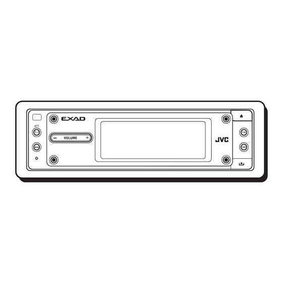
Page 77: Location Of The Buttons
Location of the Buttons Control panel T/P button Activates or deactivates TA Standby (Standby/On/Attenuator) button Reception (and Road Traffic News Turns on and off the power, and also attenuates Standby Reception). the sounds. 0 (eject) button Remote VOLUME+/– button Open the control panel (and eject the sensor* Adjust the volume level. - Page 78 Remote controller (Standby/On/Attenuator) button ANGLE button Adjust the control panel angle. BAND button SOURCE button Select the band for FM/AM and Select the source. DAB. 5/∞ buttons 4/¢ buttons • Change the preset stations. • Searches for stations (or • Change the services for ensembles)—Auto Search, if DAB.
-
Page 79: Basic Operations
Basic Operations Turn on the power Adjust the volume Hold Hold The Operation screen for last selected source is recalled. Select the source Adjust the sound You can also change the source by..• For details, see pages 24 to 26. When operating the touch panel Make sure to touch the area inside the key icon boundary, but not on the boundary. -
Page 80: Canceling The Display Demonstration
What information is shown on the touch panel The following information are shown commonly for all sources. • If you press DISP on the control panel, the touch panel will show the different information or different screens. (Details about this will be explained later separately for each source.) Current source Current source i-EQ setting... -
Page 81: Setting The Clock
Exit Select “Clock Min.” To activate the display demonstration, repeat the same procedure and select any one other than “Off” in step 3 . • For more details, see “To show the display demonstration” on page 35. ○ ○ ○ ○ ○ ○ ○ ○ ○ Adjust the minute. -
Page 82: Radio Operations
Radio Operations ○ ○ ○ ○ ○ ○ ○ ○ Listening to the radio Start searching for a station Select the Tuner You can also change the source by..“Auto Search” begins. When a station is received, searching stops. Then just wait. To stop searching, press the same icon. -
Page 83: Storing Stations In Memory
When an FM stereo broadcast is hard to Hold receive: Local FM stations with the strongest signals are searched and stored automatically in the selected FM band. Manual presetting Ex. Storing an FM station of 92.5 MHz into the preset number 1 of the FM1 band. Reception improves, but stereo (in this example, FM1) effect will be lost. -
Page 84: Tuning In To A Preset Station
○ ○ ○ ○ ○ ○ ○ ○ ○ ○ ○ ○ ○ ○ ○ ○ ○ ○ Tuning in to a preset station Changing the display pattern Select a preset Tuner Operation screen number. Station name (PS) for FM RDS stations To select a preset station using the Preset Station List •... -
Page 85: Fm Rds Operations
FM RDS Operations ○ ○ ○ ○ ○ ○ ○ ○ Searching for your favorite Select “PTY SEARCH” ○ ○ ○ ○ ○ ○ ○ ○ programme You can tune in to a station broadcasting Preset PTY Code List your favorite programme by searching for a appears (see below). - Page 86 What you can do with RDS RDS (Radio Data System) allows FM stations to send an additional signal along with their regular programme signals. For example, the stations send their station names, as well as information about what type of programme they broadcast, such as sports or music, etc. By receiving the RDS data, this unit can do the following: •...
-
Page 87: Using The Standby Reception
○ ○ ○ ○ ○ ○ ○ ○ ○ Using the Standby Reception Using PTY Standby Reception PTY Standby Reception allows the unit to You can use two types of Standby Reception— switch temporarily to your favorite programme TA Standby Reception and PTY Standby (PTY: Programme Type) from any source other Reception. -
Page 88: Tracking The Same Programme
○ ○ ○ ○ ○ ○ ○ ○ ○ Tracking the same programme— To activate PTY Standby Reception • After activating PTY Standby Reception, you ○ ○ ○ ○ ○ ○ ○ ○ ○ Network-Tracking Reception can change the source without canceling PTY Standby Reception (except to AM). -
Page 89: Using Programme Search
Exit Select “TUNER.” Now “PTY Stnby” setting appears. AF or REG indicator ○ ○ ○ ○ ○ ○ ○ ○ ○ Using Programme Search When you select a preset station, the station of Select “AF-Regn’l.” the frequency stored is tuned in. However, when the preset station is an RDS station, something different will happen with Programme Search activated. - Page 90 Exit Select “P-Search.” To deactivate Programme Search, follow the procedure above and select “Off” in step 5 . Select “On.” Activates Programme Search. Off: Cancels the Search. PTY codes News: News Social: Programmes on social activities Affairs: Topical programmes expanding on Religion: Programmes dealing with any current news or affairs aspect of belief or faith, or the...
-
Page 91: Basic Disc Operations
Basic Disc Operations To fast-forward or reverse the track: Open the control panel The unit turns on, then... Hold Hold To go to the next or previous tracks: Insert a disc To go to the next or previous folders: The unit draws the disc, the control panel For MP3/WMA discs only: closes then goes back to the previous position (see page 42), and playback starts... - Page 92 About MP3 and WMA discs ® Level 1 Level 2 Level 3 Level 4 Level 5 MP3 and WMA (Windows Media Audio) “tracks” (words “file” and “track” are used interchangeably) are recorded in “folders.” ROOT “Root” is similar to the root of a tree. Every track and folder can be linked to and be accessed from the root.
-
Page 93: Advanced Disc Operations
Advanced Disc Operations ○ ○ ○ ○ ○ ○ ○ ○ ○ Locating a track or folder on a disc • If you select the currently selected folder (highlighted on the screen), the File List To locate a folder on the screen (only screen (see step 3 below), then you can for MP3/WMA discs) select a track to start with. -
Page 94: Prohibiting Disc Ejection
To locate a track (or folder) directly using the remote controller • To select a track (or folder for MP3 and WMA discs) number from 1 – 6: (3 times) First time you press “+10” or “–10,” the track skips to the nearest higher or lower •... -
Page 95: Selecting Playback Modes
○ ○ ○ ○ ○ ○ ○ ○ ○ Selecting playback modes To play back tracks repeatedly (Repeat Play) You can use only one of the following playback You can repeat playback. modes at a time. To play back only intros (Intro Scan) You can play back the first 15 seconds of each track sequentially. -
Page 96: Changing The Display Pattern
○ ○ ○ ○ ○ ○ ○ ○ ○ Changing the display pattern To play back tracks at random (Random Play) You can play back tracks at random. Disc Operation screen Folder Disc Clock time is enlarged. Mode Plays randomly Folder* : All tracks of the current folder, then moves to the next folder and so on. -
Page 97: Sound Adjustments
Sound Adjustments ○ ○ ○ ○ ○ ○ ○ ○ Setting the basic sound selection Adjust the item ○ ○ ○ ○ ○ ○ ○ ○ menu—SEL To adjust fader and balance: Show the Main Menu To select the cutoff frequency and adjust Show the basic sound the subwoofer output level: selection menu... -
Page 98: Selecting Preset Sound Modes
○ ○ ○ ○ ○ ○ ○ ○ ○ To adjust subwoofer output—SUB OUT: Selecting preset sound modes Select an appropriate cutoff frequency level ○ ○ ○ ○ ○ ○ ○ ○ ○ (i-EQ: intelligent equalizer) according to the subwoofer connected. You can select a sound mode suitable to the music genre. -
Page 99: Storing Your Own Sound Modes
○ ○ ○ ○ ○ ○ ○ ○ ○ Storing your own sound modes Repeat steps 2 and 3 to adjust the other frequency bands. You can adjust the sound modes and store your own adjustments in memory. Repeat steps 1 to 3 on page 25 to select a sound mode you want to adjust. -
Page 100: Graphic Displays
Graphic Displays ○ ○ ○ ○ ○ ○ ○ ○ Basic procedure Show the Main Menu Before starting the following procedure, prepare a CD-R including still images (pictures) and animations (movies). • With Image Converter (Wide) included in the supplied CD-ROM, you can create your own images and animations. -
Page 101: Downloading The File For "Opening/ Ending/Movie
IMPORTANT: • Refer to Image Converter PDF files included in the “Manual” folder of the supplied CD- ROM. • Still images (pictures) should have <jll>, and animations (movies) should have <jla> as their extension code in their file names. • Before you download or delete the files, observe the following: –... -
Page 102: Downloading The Files For "Picture
To delete the stored animation: Repeat steps 1 to 4 on page 27, then in step 5 ... Only the folders including the <jll> files are shown. (once for the Select a folder. currently selected; twice for the others) File name of the stored file appears. Select a file. - Page 103 Download more files if you want. • To select a file from the same folder: Delete more files if you want. • To select a file from another folder: Repeat steps 3 to 5 . Select a file. After deleting all the files you do not After downloading all the files you want...
-
Page 104: Deleting All Files
○ ○ ○ ○ ○ ○ ○ ○ ○ Deleting all files You can easily delete all files—animations and pictures stored for “OPENING/ENDING/ MOVIE/PICTURE.” Select “MOVIE.” Now “Demo” setting appears. Select “Opening” or “Ending.” Select “User.” Default: Factory-preset animation is used. User: Your own animation is used. - Page 105 To select a still image for “UserPict.” • If “UserPict.” is not selected for “Graphics” you cannot select “UserPict.” in step 4 below. Select “MOVIE.” Now “Demo” setting appears . The last selected item appears. Select “Graphics.” Select “MOVIE.” Now “Demo” setting appears .
-
Page 106: General Settings-Psm
General Settings—PSM ○ ○ ○ ○ ○ ○ ○ ○ Basic procedure Select a PSM item You can change the Preferred Setting Mode (PSM) items listed on the table that follows. • The PSM items are grouped into six categories—MOVIE, CLOCK, DISP (display), TUNER, AUDIO, and COLOR. - Page 107 PSM items Selectable settings Initial Pages All Time ImageLink Demo Demonstration Interval 7, 35 Interval UserMovie UserPict. Graphics Graphics UserPict. UserSlide KeyIn CFM Key-in confirmation Opening Opening screen Default User Default Ending Ending screen Default User Default UserPict. User picture First stored From the stored files Clock Hr...
- Page 108 PSM items Selectable settings Initial Pages Beep Voice Voice support system Voice VSS Level VSS level Deutsch English Language Language English Français Ext Input External Input Changer Line In Changer Muting2 Muting1 Telephone Telephone mute Amp Gain Amp gain control High PWR Low PWR High PWR...
- Page 109 To select the scroll mode—Scroll To turn the tag display on or off—Tag The entire text information is shown by An MP3 and WMA track can contain track scrolling if it cannot be shown at a time. information called “Tag” where its album •...
- Page 110 • Changer: To use a JVC CD changer. interference noise will be reduced. • Line In: To use any external component. (But the stereo effect will also be To select the telephone muting lost.)
-
Page 111: Selecting The Dimmer Mode
○ ○ ○ ○ ○ ○ ○ ○ ○ Selecting the dimmer mode You can dim the display at night automatically or as you set the timer. Select “From–To.” Set the dimmer start time. The last selected item appears. Select “DISP.” Now “Scroll”... -
Page 112: Changing The Display Color
○ ○ ○ ○ ○ ○ ○ ○ ○ Changing the display color You can select your favorite color for each source (or for all sources). Setting the desired color for the source Select the color. O Aqua O Sky O Sea O Every* Leaves O Grass O Apple O Rose O Amber O Honey O Violet O Grape O... - Page 113 Creating your own color—User Adjust the selected user color. You can create your own colors—“USER DAY” and “USER NIGHT,” and select them for the display color. • USER DAY: Can be used as your user color during the day time*. •...
-
Page 114: Other Main Functions
Other Main Functions ○ ○ ○ ○ ○ ○ ○ ○ ○ Assigning titles to the sources You can assign titles 40 CDs (both in this unit and in the CD changer) and the external component. Select a character. Source Maximum number CDs: 32 characters... -
Page 115: Changing The Control Panel Angle
○ ○ ○ ○ ○ ○ ○ ○ ○ ○ ○ ○ ○ ○ ○ ○ ○ ○ Detaching the control panel Changing the control panel angle • When detaching and attaching the control You can change the angle of the control panel. panel, be careful not to damage the connectors. -
Page 116: Basic Cd Changer Operations
Basic CD Changer Operations With JVC MP3-compatible CD changer To fast-forward or reverse the track: connected, you can play back your original CD-Rs and CD-RWs recorded either in audio CD format or in MP3 format. Select CD changer Hold Hold... - Page 117 (track) indicator appears instead of the track name. Before operating your CD changer: It is recommended to use the JVC MP3- compatible CD changer with your unit. • Refer also to the Instructions supplied with • You can also connect the CH-X series your CD changer.
-
Page 118: Advanced Cd Changer Operations
Hold Main touch panels used in this section CD Changer Mode screen Disc List screen* Works only when JVC MP3 compatible CD changer (CH-X1500) is connected. The lists show the disc names actually recorded or assigned (the first 8 characters, Appears only for MP3 discs. -
Page 119: Locating A Track Or Folder On A Disc
Main touch panels used in this section File (Track) List screen (only for MP3)* Folder List screen (only for MP3)* The lists show the folder/file names actually recorded (the first 8 characters). Press to go to the next list; hold to go back to •... - Page 120 You can quickly reach a desired track on a disc including many tracks. • This operation is only possible when using a JVC MP3 compatible CD changer (CH-X1500) . • For MP3 discs, you can select only a track within the current folder.
-
Page 121: Selecting Playback Modes
○ ○ ○ ○ ○ ○ ○ ○ ○ Selecting playback modes To play back tracks repeatedly (Repeat Play) You can use only one of the following playback You can repeat playback. modes at a time. To play back only intros (Intro Scan) You can play back the first 15 seconds of each track sequentially. -
Page 122: Changing The Display Pattern
○ ○ ○ ○ ○ ○ ○ ○ ○ To play back tracks at random (Random Changing the display pattern Play) You can play back tracks at random. CD Changer Operation screen Folder Disc Mode Plays randomly Clock time is enlarged. Folder* : All tracks of the current folder, then moves to the next folder and so on. -
Page 123: External Component Operations
External Component Operations You can connect the external component Adjust the volume to the CD changer jack on the rear using the special adapter for the component (not Hold Hold supplied). See the Installation/Connection Manual (separate volume). • Before operating the external component, select the “Ext Input”... -
Page 124: Dab Tuner Operations
DAB Tuner Operations ○ ○ ○ ○ ○ ○ ○ ○ Listening to the DAB tuner Start searching for an ensemble Select the DAB Tuner You can also change the source by..“Auto Search” begins. When a station is received, searching stops. Then just wait. - Page 125 (services) broadcast at the same time. It is recommended to use DAB (Digital Audio Broadcasting) tuner KT-DB1500 or KT-DB1000 with this unit. If you have another DAB tuner, consult your JVC IN-CAR ENTERTAINMENT dealer. • Refer also to the Instructions supplied with your DAB tuner.
-
Page 126: Storing Dab Services In Memory
To search for your favorite service You can search for any one of the PTY codes (either Dynamic or Static PTY). • Operations are exactly the same as explained on pages 12 and 13 for FM RDS stations. • You cannot store PTY codes separately for the DAB tuner and for the FM tuner. -
Page 127: Using The Standby Reception
To activate Road Traffic News Standby Reception (and TA Standby Reception): TP indicator (either lights up or flashes) • If the TP indicator lights up, Road Traffic News Standby Reception (or TA Standby Select a preset number. Reception) is activated. –... - Page 128 Using Announcement Standby Reception Announcement Standby Reception allows the unit to switch temporarily to your favorite service (Announcement type) from any source except AM. To select your favorite announcement type for Select an announcement type. Announcement Standby Reception Travel: Programmes about travel You can select your favorite announcement destinations, package tours, and type for Announcement Standby Reception.
-
Page 129: Tracing The Same Programme
Using PTY Standby Reception PTY Standby Reception allows the unit to switch temporarily to your favorite programme (PTY: Programme Type) from any source except AM stations • Operations are exactly the same as explained Announcement type on pages 14 and 15 for FM RDS stations. (Travel, Warning, etc.) •... -
Page 130: Changing The Display Pattern
○ ○ ○ ○ ○ ○ ○ ○ ○ Changing the display pattern The last selected item appears. DAB Tuner Operation screen Service label Ensemble label Select “TUNER.” Now “PTY Stnby” setting appears. Preset number Lights when receiving a if any service providing Dynamic Label Segment (DLS—DAB radio text). -
Page 131: Maintenance
Maintenance How to clean the touch panel How to handle discs Center holder When removing stains or dust on the surface, When removing a disc from turn off the power, then wipe with dry soft its case, press down the center cloth. -
Page 132: More About This Receiver
More about This Receiver ○ ○ ○ ○ ○ ○ ○ ○ ○ ○ ○ ○ ○ ○ ○ ○ ○ ○ Basic Operations Tuner Operations General Storing stations in memory • The clock in the “BACK” icon on the screen •... - Page 133 ○ ○ ○ ○ ○ ○ ○ ○ ○ Basic Disc Operations When playing a CD-R or CD-RW • Use only “finalized” CD-Rs or CD-RWs. General • Some CD-Rs or CD-RWs may not play back • This unit has been designed to reproduce on this unit because of their disc CDs/CD Texts, and CD-Rs (Recordable)/ characteristics, and for the following causes:...
- Page 134 ImageLink Storing your own sound modes • ImageLink will not work in the following • If you do not want to store your current cases: adjustment, but only to apply the adjustment – If no <jll> file is included in an MP3/WMA to the current playback source, press folder.
- Page 135 ○ ○ ○ ○ ○ ○ ○ ○ ○ ○ ○ ○ ○ ○ ○ ○ ○ ○ General Settings—PSM DAB Tuner Operations • “Auto Dimmer” may not work correctly on • PTY Standby Reception works for the DAB some vehicles, particularly on those having a tuner only using a Dynamic PTY, but not a control dial for dimming.
-
Page 136: Troubleshooting
Troubleshooting What appears to be trouble is not always • Disc cannot be recognized (“No Disc,” serious. Check the following points before “Loading Error,” or “Eject Error” calling a service center. flashes). ] The CD player may function incorrectly. and 0 at the same time Press General for more than 2 seconds to display the... - Page 137 • “No Files” appears for a while, then the • “Opening” and “Ending” cannot be disc ejects. selected. ] The current MP3/WMA disc does not ] If “KeyIn CFM” is set to “Off,” you contain any MP3/WMA tracks. cannot select them. •...
-
Page 138: Specifications
Specifications AUDIO AMPLIFIER SECTION [MW Tuner] Sensitivity: 20 µV Maximum Power Output: Front: 50 W per channel Selectivity: 65 dB Rear: 50 W per channel [LW Tuner] Continuous Power Output (RMS): Sensitivity: 50 µV 19 W per channel into 4 Ω, 40 Hz Front: to 20 000 Hz at no more than CD PLAYER SECTION... - Page 139 Having TROUBLE with operation? Please reset your unit Refer to page of How to reset your unit Haben Sie PROBLEME mit dem Betrieb? Bitte setzen Sie Ihr Gerät zurück Siehe Seite Zurücksetzen des Geräts Vous avez des PROBLÈMES de fonctionnement? Réinitialisez votre appareil Référez-vous à...
- Page 140 JVC IN-CAR ENTERTAINMENT dealer or brauchen, wenden Sie sich an ihren JVC inbouwpakketten contact op met uw JVC car audio a company supplying kits. Autoradiohändler oder ein Unternehmen das d’autoradios JVC ou une compagnie dealer of een dealer of een bedrijf dat •...
- Page 141 JVC IN-CAR ENTERTAINMENT dealer. Nennleistung ersetzen. Brennt die Sicherung • Remplacer le fusible par un de la valeur doorslaat, moet u uw JVC car audio dealer • It is recommended to connect to the speakers häufig durch, wenden Sie sich an ihren JVC précisée.
- Page 142 NEDERLANDS ENGLISH DEUTSCH FRANÇAIS If your car is equipped with the ISO connector For some VW/Audi or Opel (Vauxhall) automobile Wenn Ihr Auto mit ISO-Steckern ausgestattet ist Für manche VW/Audi oder Opel (Vauxhall) Fahrzeuge Si votre voiture est équippée d’un connecteur ISO Pour certaine voiture VW/Audi ou Opel (Vauxhall) Indien uw auto is uitgerust met de ISO-connector Voor bepaalde modellen VW/Audi of Opel (Vauxhall) geldt...
- Page 143 If your car is equipped with the steering wheel remote controller, you can operate this receiver using the Radio-Lenkrad-Fernbedienungsadaption controller. To do it, a JVC’s OE remote adapter (not supplied) which matches with your car is required. (nicht im Lieferumfang enthalten) Steering wheel remote input Consult your JVC IN-CAR ENTERTAINMENT dealer for details.
- Page 144 CD RECEIVER RECEPTOR CON CD RECEPTEUR CD CD RECE∑VER KD-LHX502/KD-LHX501 This unit is equipped with the display demonstration. To cancel it, see page 7. Esta unidad está equipada con la demostración en indicación. Para cancelarla, consulte la página 7. Cet appareil est équipé d’une démonstration des affichages. Pour l’annuler, référez- vous à...
- Page 145 Thank you for purchasing a JVC product. Please read all instructions carefully before operation, to ensure your complete understanding and to obtain the best possible performance from the unit. IMPORTANT FOR LASER PRODUCTS 1. CLASS 1 LASER PRODUCT 2. CAUTION: Do not open the top cover. There are no user serviceable parts inside the unit;...
- Page 146 Contents How to reset your unit ........2 General Settings—PSM ......33 Basic procedure ..........33 Location of the Buttons ......... 4 Selecting the dimmer mode ......38 Basic Operations ..........6 Changing the display color ......39 Canceling the display demonstration ....7 Other Main Functions .........
-
Page 147: Location Of The Buttons
Location of the Buttons Control panel T/P button Activates or deactivates TA Standby (Standby/On/Attenuator) button Reception (and Road Traffic News Turns on and off the power, and also attenuates Standby Reception). the sounds. 0 (eject) button Remote VOLUME+/– button Open the control panel (and eject the sensor* Adjust the volume level. - Page 148 Remote controller (Standby/On/Attenuator) button ANGLE button Adjust the control panel angle. BAND button SOURCE button Select the band for FM/AM and Select the source. DAB. 5/∞ buttons 4/¢ buttons • Change the preset stations. • Searches for stations (or • Change the services for ensembles)—Auto Search, if DAB.
-
Page 149: Basic Operations
Basic Operations Turn on the power Adjust the volume Hold Hold The Operation screen for last selected source is recalled. Select the source Adjust the sound You can also change the source by..• For details, see pages 24 to 26. When operating the touch panel Make sure to touch the area inside the key icon boundary, but not on the boundary. -
Page 150: Canceling The Display Demonstration
What information is shown on the touch panel The following information are shown commonly for all sources. • If you press DISP on the control panel, the touch panel will show the different information or different screens. (Details about this will be explained later separately for each source.) Current source Current source i-EQ setting... -
Page 151: Setting The Clock
Exit Select “Clock Min.” To activate the display demonstration, repeat the same procedure and select any one other than “Off” in step 3 . • For more details, see “To show the display demonstration” on page 35. ○ ○ ○ ○ ○ ○ ○ ○ ○ Adjust the minute. -
Page 152: Radio Operations
Radio Operations ○ ○ ○ ○ ○ ○ ○ ○ Listening to the radio Start searching for a station Select the Tuner You can also change the source by..“Auto Search” begins. When a station is received, searching stops. Then just wait. To stop searching, press the same icon. -
Page 153: Storing Stations In Memory
When an FM stereo broadcast is hard to Hold receive: Local FM stations with the strongest signals are searched and stored automatically in the selected FM band. Manual presetting Ex. Storing an FM station of 92.5 MHz into the preset number 1 of the FM1 band. Reception improves, but stereo (in this example, FM1) effect will be lost. -
Page 154: Tuning In To A Preset Station
○ ○ ○ ○ ○ ○ ○ ○ ○ ○ ○ ○ ○ ○ ○ ○ ○ ○ Tuning in to a preset station Changing the display pattern Select a preset Tuner Operation screen number. Station name (PS) for FM RDS stations To select a preset station using the Preset Station List •... -
Page 155: Fm Rds Operations
FM RDS Operations ○ ○ ○ ○ ○ ○ ○ ○ Searching for your favorite Select “PTY SEARCH” ○ ○ ○ ○ ○ ○ ○ ○ programme You can tune in to a station broadcasting Preset PTY Code List your favorite programme by searching for a appears (see below). - Page 156 What you can do with RDS RDS (Radio Data System) allows FM stations to send an additional signal along with their regular programme signals. For example, the stations send their station names, as well as information about what type of programme they broadcast, such as sports or music, etc. By receiving the RDS data, this unit can do the following: •...
-
Page 157: Using The Standby Reception
○ ○ ○ ○ ○ ○ ○ ○ ○ Using the Standby Reception Using PTY Standby Reception PTY Standby Reception allows the unit to You can use two types of Standby Reception— switch temporarily to your favorite programme TA Standby Reception and PTY Standby (PTY: Programme Type) from any source other Reception. -
Page 158: Tracking The Same Programme
○ ○ ○ ○ ○ ○ ○ ○ ○ Tracking the same programme— To activate PTY Standby Reception • After activating PTY Standby Reception, you ○ ○ ○ ○ ○ ○ ○ ○ ○ Network-Tracking Reception can change the source without canceling PTY Standby Reception (except to AM). -
Page 159: Using Programme Search
Exit Select “TUNER.” Now “PTY Stnby” setting appears. AF or REG indicator ○ ○ ○ ○ ○ ○ ○ ○ ○ Using Programme Search When you select a preset station, the station of Select “AF-Regn’l.” the frequency stored is tuned in. However, when the preset station is an RDS station, something different will happen with Programme Search activated. - Page 160 Exit Select “P-Search.” To deactivate Programme Search, follow the procedure above and select “Off” in step 5 . Select “On.” Activates Programme Search. Off: Cancels the Search. PTY codes News: News Social: Programmes on social activities Affairs: Topical programmes expanding on Religion: Programmes dealing with any current news or affairs aspect of belief or faith, or the...
-
Page 161: Basic Disc Operations
Basic Disc Operations To fast-forward or reverse the track: Open the control panel The unit turns on, then... Hold Hold To go to the next or previous tracks: Insert a disc To go to the next or previous folders: The unit draws the disc, the control panel For MP3/WMA discs only: closes then goes back to the previous position (see page 42), and playback starts... - Page 162 About MP3 and WMA discs ® Level 1 Level 2 Level 3 Level 4 Level 5 MP3 and WMA (Windows Media Audio) “tracks” (words “file” and “track” are used interchangeably) are recorded in “folders.” ROOT “Root” is similar to the root of a tree. Every track and folder can be linked to and be accessed from the root.
-
Page 163: Advanced Disc Operations
Advanced Disc Operations ○ ○ ○ ○ ○ ○ ○ ○ ○ Locating a track or folder on a disc • If you select the currently selected folder (highlighted on the screen), the File List To locate a folder on the screen (only screen (see step 3 below), then you can for MP3/WMA discs) select a track to start with. -
Page 164: Prohibiting Disc Ejection
To locate a track (or folder) directly using the remote controller • To select a track (or folder for MP3 and WMA discs) number from 1 – 6: (3 times) First time you press “+10” or “–10,” the track skips to the nearest higher or lower •... -
Page 165: Selecting Playback Modes
○ ○ ○ ○ ○ ○ ○ ○ ○ Selecting playback modes To play back tracks repeatedly (Repeat Play) You can use only one of the following playback You can repeat playback. modes at a time. To play back only intros (Intro Scan) You can play back the first 15 seconds of each track sequentially. -
Page 166: Changing The Display Pattern
○ ○ ○ ○ ○ ○ ○ ○ ○ Changing the display pattern To play back tracks at random (Random Play) You can play back tracks at random. Disc Operation screen Folder Disc Clock time is enlarged. Mode Plays randomly Folder* : All tracks of the current folder, then moves to the next folder and so on. -
Page 167: Sound Adjustments
Sound Adjustments ○ ○ ○ ○ ○ ○ ○ ○ Setting the basic sound selection Adjust the item ○ ○ ○ ○ ○ ○ ○ ○ menu—SEL To adjust fader and balance: Show the Main Menu To select the cutoff frequency and adjust Show the basic sound the subwoofer output level: selection menu... -
Page 168: Selecting Preset Sound Modes
○ ○ ○ ○ ○ ○ ○ ○ ○ To adjust subwoofer output—SUB OUT: Selecting preset sound modes Select an appropriate cutoff frequency level ○ ○ ○ ○ ○ ○ ○ ○ ○ (i-EQ: intelligent equalizer) according to the subwoofer connected. You can select a sound mode suitable to the music genre. -
Page 169: Storing Your Own Sound Modes
○ ○ ○ ○ ○ ○ ○ ○ ○ Storing your own sound modes Repeat steps 2 and 3 to adjust the other frequency bands. You can adjust the sound modes and store your own adjustments in memory. Repeat steps 1 to 3 on page 25 to select a sound mode you want to adjust. -
Page 170: Graphic Displays
Graphic Displays ○ ○ ○ ○ ○ ○ ○ ○ Basic procedure Show the Main Menu Before starting the following procedure, prepare a CD-R including still images (pictures) and animations (movies). • With Image Converter (Wide) included in the supplied CD-ROM, you can create your own images and animations. -
Page 171: Downloading The File For "Opening
IMPORTANT: • Refer to Image Converter PDF files included in the “Manual” folder of the supplied CD- ROM. • Still images (pictures) should have <jll>, and animations (movies) should have <jla> as their extension code in their file names. • Before you download or delete the files, observe the following: –... -
Page 172: Downloading The Files For "Picture
To delete the stored animation: Repeat steps 1 to 4 on page 27, then in step 5 ... Only the folders including the <jll> files are shown. (once for the Select a folder. currently selected; twice for the others) File name of the stored file appears. Select a file. - Page 173 Download more files if you want. • To select a file from the same folder: Delete more files if you want. • To select a file from another folder: Repeat steps 3 to 5 . Select a file. After deleting all the files you do not After downloading all the files you want...
-
Page 174: Deleting All Files
○ ○ ○ ○ ○ ○ ○ ○ ○ Deleting all files You can easily delete all files—animations and pictures stored for “OPENING/ENDING/ MOVIE/PICTURE.” Select “MOVIE.” Now “Demo” setting appears. Select “Opening” or “Ending.” Select “User.” Default: Factory-preset animation is used. User: Your own animation is used. - Page 175 To select a still image for “UserPict.” • If “UserPict.” is not selected for “Graphics” you cannot select “UserPict.” in step 4 below. Select “MOVIE.” Now “Demo” setting appears . The last selected item appears. Select “Graphics.” Select “MOVIE.” Now “Demo” setting appears .
-
Page 176: General Settings-Psm
General Settings—PSM ○ ○ ○ ○ ○ ○ ○ ○ Basic procedure Select a PSM item You can change the Preferred Setting Mode (PSM) items listed on the table that follows. • The PSM items are grouped into six categories—MOVIE, CLOCK, DISP (display), TUNER, AUDIO, and COLOR. - Page 177 PSM items Selectable settings Initial Pages All Time ImageLink Demo Demonstration Interval 7, 35 Interval UserMovie UserPict. Graphics Graphics UserPict. UserSlide KeyIn CFM Key-in confirmation Opening Opening screen Default User Default Ending Ending screen Default User Default UserPict. User picture First stored From the stored files Clock Hr...
- Page 178 PSM items Selectable settings Initial Pages Beep Voice Voice support system Voice VSS Level VSS level Deutsch English Language Language English Français Ext Input External Input Changer Line In Changer Muting2 Muting1 Telephone Telephone mute Amp Gain Amp gain control High PWR Low PWR High PWR...
- Page 179 To select the scroll mode—Scroll To turn the tag display on or off—Tag The entire text information is shown by An MP3 and WMA track can contain track scrolling if it cannot be shown at a time. information called “Tag” where its album •...
- Page 180 • Changer: To use a JVC CD changer. interference noise will be reduced. • Line In: To use any external component. (But the stereo effect will also be To select the telephone muting lost.)
-
Page 181: Selecting The Dimmer Mode
○ ○ ○ ○ ○ ○ ○ ○ ○ Selecting the dimmer mode You can dim the display at night automatically or as you set the timer. Select “From–To.” Set the dimmer start time. The last selected item appears. Select “DISP.” Now “Scroll”... -
Page 182: Changing The Display Color
○ ○ ○ ○ ○ ○ ○ ○ ○ Changing the display color You can select your favorite color for each source (or for all sources). Setting the desired color for the source Select the color. O Aqua O Sky O Sea O Every* Leaves O Grass O Apple O Rose O Amber O Honey O Violet O Grape O... - Page 183 Creating your own color—User Adjust the selected user color. You can create your own colors—“USER DAY” and “USER NIGHT,” and select them for the display color. • USER DAY: Can be used as your user color during the day time*. •...
-
Page 184: Other Main Functions
Other Main Functions ○ ○ ○ ○ ○ ○ ○ ○ ○ Assigning titles to the sources You can assign titles 40 CDs (both in this unit and in the CD changer) and the external component. Select a character. Source Maximum number CDs: 32 characters... -
Page 185: Changing The Control Panel Angle
○ ○ ○ ○ ○ ○ ○ ○ ○ ○ ○ ○ ○ ○ ○ ○ ○ ○ Detaching the control panel Changing the control panel angle • When detaching and attaching the control You can change the angle of the control panel. panel, be careful not to damage the connectors. -
Page 186: Basic Cd Changer Operations
Basic CD Changer Operations With JVC MP3-compatible CD changer To fast-forward or reverse the track: connected, you can play back your original CD-Rs and CD-RWs recorded either in audio CD format or in MP3 format. Select CD changer Hold Hold... - Page 187 (track) indicator appears instead of the track name. Before operating your CD changer: It is recommended to use the JVC MP3- compatible CD changer with your unit. • Refer also to the Instructions supplied with • You can also connect the CH-X series your CD changer.
-
Page 188: Advanced Cd Changer Operations
Hold Main touch panels used in this section CD Changer Mode screen Disc List screen* Works only when JVC MP3 compatible CD changer (CH-X1500) is connected. The lists show the disc names actually recorded or assigned (the first 8 characters, Appears only for MP3 discs. -
Page 189: Locating A Track Or Folder On A Disc
Main touch panels used in this section File (Track) List screen (only for MP3)* Folder List screen (only for MP3)* The lists show the folder/file names actually recorded (the first 8 characters). Press to go to the next list; hold to go back to •... - Page 190 You can quickly reach a desired track on a disc including many tracks. • This operation is only possible when using a JVC MP3 compatible CD changer (CH-X1500) . • For MP3 discs, you can select only a track within the current folder.
-
Page 191: Selecting Playback Modes
○ ○ ○ ○ ○ ○ ○ ○ ○ Selecting playback modes To play back tracks repeatedly (Repeat Play) You can use only one of the following playback You can repeat playback. modes at a time. To play back only intros (Intro Scan) You can play back the first 15 seconds of each track sequentially. -
Page 192: Changing The Display Pattern
○ ○ ○ ○ ○ ○ ○ ○ ○ To play back tracks at random (Random Changing the display pattern Play) You can play back tracks at random. CD Changer Operation screen Folder Disc Mode Plays randomly Clock time is enlarged. Folder* : All tracks of the current folder, then moves to the next folder and so on. -
Page 193: External Component Operations
External Component Operations You can connect the external component Adjust the volume to the CD changer jack on the rear using the special adapter for the component (not Hold Hold supplied). See the Installation/Connection Manual (separate volume). • Before operating the external component, select the “Ext Input”... -
Page 194: Dab Tuner Operations
DAB Tuner Operations ○ ○ ○ ○ ○ ○ ○ ○ Listening to the DAB tuner Start searching for an ensemble Select the DAB Tuner You can also change the source by..“Auto Search” begins. When a station is received, searching stops. Then just wait. - Page 195 (services) broadcast at the same time. It is recommended to use DAB (Digital Audio Broadcasting) tuner KT-DB1500 or KT-DB1000 with this unit. If you have another DAB tuner, consult your JVC IN-CAR ENTERTAINMENT dealer. • Refer also to the Instructions supplied with your DAB tuner.
-
Page 196: Storing Dab Services In Memory
To search for your favorite service You can search for any one of the PTY codes (either Dynamic or Static PTY). • Operations are exactly the same as explained on pages 12 and 13 for FM RDS stations. • You cannot store PTY codes separately for the DAB tuner and for the FM tuner. -
Page 197: Using The Standby Reception
To activate Road Traffic News Standby Reception (and TA Standby Reception): TP indicator (either lights up or flashes) • If the TP indicator lights up, Road Traffic News Standby Reception (or TA Standby Select a preset number. Reception) is activated. –... - Page 198 Using Announcement Standby Reception Announcement Standby Reception allows the unit to switch temporarily to your favorite service (Announcement type) from any source except AM. To select your favorite announcement type for Select an announcement type. Announcement Standby Reception Travel: Programmes about travel You can select your favorite announcement destinations, package tours, and type for Announcement Standby Reception.
-
Page 199: Tracing The Same Programme
Using PTY Standby Reception PTY Standby Reception allows the unit to switch temporarily to your favorite programme (PTY: Programme Type) from any source except AM stations • Operations are exactly the same as explained Announcement type on pages 14 and 15 for FM RDS stations. (Travel, Warning, etc.) •... -
Page 200: Changing The Display Pattern
○ ○ ○ ○ ○ ○ ○ ○ ○ Changing the display pattern The last selected item appears. DAB Tuner Operation screen Service label Ensemble label Select “TUNER.” Now “PTY Stnby” setting appears. Preset number Lights when receiving a if any service providing Dynamic Label Segment (DLS—DAB radio text). -
Page 201: Maintenance
Maintenance How to clean the touch panel How to handle discs Center holder When removing stains or dust on the surface, When removing a disc from turn off the power, then wipe with dry soft its case, press down the center cloth. -
Page 202: More About This Receiver
More about This Receiver ○ ○ ○ ○ ○ ○ ○ ○ ○ ○ ○ ○ ○ ○ ○ ○ ○ ○ Basic Operations Tuner Operations General Storing stations in memory • The clock in the “BACK” icon on the screen •... - Page 203 ○ ○ ○ ○ ○ ○ ○ ○ ○ Basic Disc Operations When playing a CD-R or CD-RW • Use only “finalized” CD-Rs or CD-RWs. General • Some CD-Rs or CD-RWs may not play back • This unit has been designed to reproduce on this unit because of their disc CDs/CD Texts, and CD-Rs (Recordable)/ characteristics, and for the following causes:...
- Page 204 ImageLink Storing your own sound modes • ImageLink will not work in the following • If you do not want to store your current cases: adjustment, but only to apply the adjustment – If no <jll> file is included in an MP3/WMA to the current playback source, press folder.
- Page 205 ○ ○ ○ ○ ○ ○ ○ ○ ○ ○ ○ ○ ○ ○ ○ ○ ○ ○ General Settings—PSM DAB Tuner Operations • “Auto Dimmer” may not work correctly on • PTY Standby Reception works for the DAB some vehicles, particularly on those having a tuner only using a Dynamic PTY, but not a control dial for dimming.
-
Page 206: Troubleshooting
Troubleshooting What appears to be trouble is not always • Disc cannot be recognized (“No Disc,” serious. Check the following points before “Loading Error,” or “Eject Error” calling a service center. flashes). ] The CD player may function incorrectly. and 0 at the same time Press General for more than 2 seconds to display the... - Page 207 • “No Files” appears for a while, then the • “Opening” and “Ending” cannot be disc ejects. selected. ] The current MP3/WMA disc does not ] If “KeyIn CFM” is set to “Off,” you contain any MP3/WMA tracks. cannot select them. •...
-
Page 208: Specifications
Specifications AUDIO AMPLIFIER SECTION [MW Tuner] Sensitivity: 20 µV Maximum Power Output: Front: 50 W per channel Selectivity: 65 dB Rear: 50 W per channel [LW Tuner] Continuous Power Output (RMS): Sensitivity: 50 µV 19 W per channel into 4 Ω, 40 Hz Front: to 20 000 Hz at no more than CD PLAYER SECTION... - Page 209 Having TROUBLE with operation? Please reset your unit Refer to page of How to reset your unit ¿Tiene PROBLEMAS con la operación? Por favor reinicialice su unidad Consulte la páfina de Cómo reposicionar su unidad Vous avez des PROBLÈMES de fonctionnement? Réinitialisez votre appareil Référez-vous à...
- Page 210 JVC de equipos de audio para automóviles o a d’autoradios JVC ou une compagnie • Bu ünitenin gerekti∂i gibi nasΩl monte d’approvisionnement.
- Page 211 50 W (both concesionario de JVC de equipos de audio votre revendeur d’autoradios JVC. • Maksimum gücü 50 W’den daha fazla alan hoparlörlere (hem önde hem de arkada, 4 Ω ila 8 Ω...
- Page 212 ENGLISH ESPAÑOL FRANÇAIS TÜRKÇE AINMENT dealers. If your car is equipped with the ISO connector For some VW/Audi or Opel (Vauxhall) automobile Si su automóvil está equipado con el conector ISO Para algunos automóviles VW/Audi u Opel (Vauxhall) Si votre voiture est équippée d’un connecteur ISO Pour certaine voiture VW/Audi ou Opel (Vauxhall) TaπΩtΩnΩzda ISO konektörü...
- Page 213 Adaptador para control remoto OE (no suministrado) Entrada del control remoto del volante controller. To do it, a JVC’s OE remote adapter (not supplied) which matches with your car is required. Adaptateur pour télécommande au volant (non fourni) de dirección Consult your JVC IN-CAR ENTERTAINMENT dealer for details.
Need help?
Do you have a question about the KD-LHX501 and is the answer not in the manual?
Questions and answers