Advertisement
Quick Links
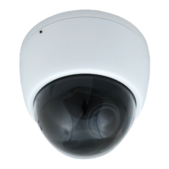
in52TS3N2D Series
Tamper Resistant Dome Camera
Quick Start Guide
Before operating this product, please read this quick-start guide to ensure proper use.
Please store these instructions a safe place for future reference.
FeaTuReS
•
Polycarbonate Housing &Bubble
•
HLC, BLC, DEFOG
•
DC Varifocal lens
•
Sens Up
•
800TVL
•
On Screen Menu
•
0.01 Lux
•
3 Axis gimbal
•
Wide Dynamic Range
•
12VDC/24VAC Powered
pReCauTioNS
1. Before installing and operating the unit, please read this manual carefully.
2. Precision components are contained in this camera, please avoid violent vibrations during
installation and maintenance. Do not connect the power until you have completed the
installation.
3. Please obey all local electrical wiring regulations when using this unit.
4. Do not use abrasive or corrosive materials for cleaning. Use only a soft cloth for cleaning.
5. To prevent damage to the lens or sensor, do not point the camera directly into the sun
or very strong light sources.
6. Do not use the camera outside it's working temperature (-10°C~ 50°C / 14°F ~122°F) or
humidity (<90%) ranges.
7. Ensure that the power supply meets the current requirements of the camera and that
the supply voltage is inside the tolerances of the camera: 12vdc or 24VAC ±10%
8. Ensure that the fixings used are adequate to support the load of camera.
9. In case of camera failure, do not attempt to dismantle or service the camera yourself.
Please refer to qualified service personnel for repair of the camera.
CoNNeCTioNS
1. Power Input connector. This is a 2 pin non-removable terminal screw connector.
Observe polarity of 12VDC connections. 24VAC power is not polarity sensitive.
Refer to the diagrams below for clarification.
2. BNC Connector, Video Output. 75Ω 1Vp-p
3. Locking grub-screw
+ (Pos)
- (Neg)
1. Using the enclosed drill template, mark and drill the four
mounting holes for the base. Choose an appropriate drill
bit for the surface you are drilling in to and ensure that the
diameter is correct for the fixings being used.
2. If rear cable exit is to be used, mark and cut a central
20mm (¾") diameter hole for the cable and connectors, as
Rev 0.1
indicated on the drill template.
3. Side cable exit. ④
4. Use appropriate No.8 countersunk screws (and wall plugs,
if applicable) for the mounting surface in use.
5. Ensure that the fixings can adequately bear the weight of
the camera.
6. Slacken the locking grub-screw and remove the dome
cover. If necessary, rotate the gimbal in axis A to gain
access to the mounting holes
7. Mount the camera and fit the O-rings in the accessory
pack to maintain a moisture proof seal.
8. Make the video and power connections and commission the camera
9. Once commissioning is complete, replace the liner, dome cover and re-tension the grub-
screw to prevent unauthorized users tampering with the camera.
The camera and integral vari-focal lens are mounted on a
3-axis gimbal with integrated liner. To remove the liner for
commissioning, gently squeeze at points B and withdraw the
liner in direction C.
To position the camera to give the required image content,
gently turn the gimbal arms ⑤ to orientate it in axis D. To adjust
the camera tilt, gently turn the gimbal disk ⑥ in axis E. To adjust
the azimuth, turn the gimbal disk in axis F.
Note: Do not use the lens as a lever to adjust the camera position
The field of view may be adjusted by loosening the zoom lever,
⑦, and moving until the required field of view is obtained.
Loosen the focus lever ⑧ and adjust to obtain optimum
focus. Remember to tighten both levers when adjustments are
complete to prevent image drift.. They should be tensioned
"finger tight" only
When complete, gently push the liner back onto the gimbal
arms, until it snaps into place.
The camera is supplied in a general configuration that will suit the majority of installation
requirements. Should advanced configuration be required then the on-board ⑨ joystick may
be used to provide access to the camera On Screen Display (OSD) for user programming.
To view the On Screen Display and image from the camera, connect a monitor to the service
jack ⑩ (use supplied molex to BNC cable) or direct to the video output of the camera.
To activate the camera OSD, depress the joystick on the
service board
Push the joystick to select a menu from the list.
Push the joystick to change the selected value.
Press the joystick button to open a sub-menu or execute a
command.
MouNTiNG
LeNS aND poSiTioNiNG
B
C
⑥
F
D
oSD aCCeSS
oSD MaiN MeNu
④
When the OSD menu is launched, you are
presented with the adjacent opening screen.
A menu option followed by a
indicates the
presence of a sub-menu. Options set to OFF will
not show a until set to ON
Use RETURN to return to the previous menu.
A
FoCuS aDJuST MeNu
FoCuS aDJuST
menu:
•
From the Main Menu, turn the Focus ADJ from OFF to ON to create a Focus Adjust
Box on the screen's bottom left
•
Move the lens to direct towards the object to be focused, and turn the lens focus
from near to far until the location from the Focus Assist Box shows a green bar.
Next turn the lens focus until the yellow bar has a similar size with the green bar
for focus. Your camera should now have a clear crisp image.
B
LeNS MeNu
⑤
E
LeNS menu:
⑦
• MoDe - ALC (Auto Iris) or ELC (Manual)
⑧
selection
• iNDooR -Default, set to fixed values
• ouTDooR- Iris and shutter will auto
adjust to lighting situation.
eXpoSuRe MeNu
eXpoSuRe
menu:
• BRiGHTNeSS - Sets the level of the overall brightness
• SHuTTeR - Auto, Manual, FLK selection,
1/50~1/60K. Set this on to reduce the
exposure time of each image. This can be
used to reduce blur in images with fast
changing content. FLK mode Use this when
flicker is observed in the image under
fluorescent lighting.
• SeNS up - Slows frame rate and increases
low light sensitivity
• aGC- Level Control -Used to adjust overall
gain
MAIN MENU
FOCUS ADJUST
EXPOSURE.
ALC
BACKLIGHT
WDR
DAY&NIGHT
WHITE BAL
AUTO
IMAGE
DNR
MIDDLE
SPECIAL
SYSTEM
EXIT
LENS
MODE
INDOOR
RETURN
RET
EXPOSURE
BRIGHTNESS 10
SHUTTER
AUTO
SENS-UP
X2
AGC
16
RETURN
RET
Advertisement

Subscribe to Our Youtube Channel
Related Manuals for InMotion in52TS3N2D Series


Summary of Contents for InMotion in52TS3N2D Series
- Page 1 ④ When the OSD menu is launched, you are mounting holes for the base. Choose an appropriate drill in52TS3N2D Series presented with the adjacent opening screen. MAIN MENU bit for the surface you are drilling in to and ensure that the A menu option followed by a ...
- Page 2 RETURN inMotion CCTV • FLip - Vertical flip of image 519 Bennet Lane Suite 100 Lewisville, Texas 75057 214-960-4640 Please visit our website for full information: www.inMotioncctv.com inMotion reserves the right to amend specifications and design without prior notice...
Need help?
Do you have a question about the in52TS3N2D Series and is the answer not in the manual?
Questions and answers