Table of Contents
Advertisement
Quick Links
in30S1x1L Rev2
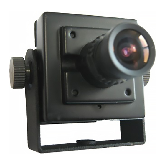
WDR ATM Camera
Quick Start Guide
Before operating this product, please read this quick-start guide to ensure proper use. Please
store these instructions in a safe place for future reference.
FEATURES
•
⅓"Pixim Digital Pixel System WDR
2850°K. Colour), 0.001Lux DSS on.
sensor and DSP
•
Programmable OSD via optional "up the
•
Resolution 690 HTVLe & pre-focussed
coax" iCCTV
High Resolution Lens
•
Selectable Progressive Scan
•
Sensitivity <0.28 Lux (F2.0, 50IRE, 30fps,
•
Multiple mounting bracket configuration
PRECAUTIONS
1. Before installing and operating the unit, please read this manual carefully.
2. Precision components are contained in this camera, please avoid violent vibrations during
installation and maintenance. Do not connect the power until you have completed the
installation.
3. Please obey all local electrical wiring regulations when using this unit.
4. Do not use abrasive or corrosive materials for cleaning. Use only a soft cloth for cleaning.
5. To prevent damage to the lens or sensor, do not point the camera directly into the sun
or very strong light sources.
6. Do not use the camera outside it's working temperature (-10°C~ 50°C / 14°F ~122°F) or
humidity (<90%) ranges.
7. Ensure that the power supply meets the current requirements of the camera and that
the supply voltage is inside the tolerances of the camera: 12VDC±10%
8. Ensure that the fixings used are adequate to support the load of camera.
9. In case of camera failure, do not attempt to dismantle or service the camera yourself.
Please refer to qualified service personnel for repair of the camera.
CONNECTIONS/CONTROLS
Connections for video and power are made to the flying lead from at the rear of the
camera. Two connectors are provided:
1. Video output connector, 75Ω BNC socket. Connect a male BNC connector to a Monitor,
DVR or UTC programmer to this socket.
2. Power Input connector. This is a 2.1mm DC jack. Observe polarity of
12VDC connections. The centre conductor is +12VDC ±10% and outer is
ground. Refer to the adjacent diagram for clarification.
3. To enable the connection to bare ended power cables, an optional
adaptor is available. Observe polarity of DC connections when using the
adaptor as mis-connection of power may damage the unit. Such damage
not covered under warranty Refer to the adjacent diagrams
4. Once connections are complete, secure the video/power flying lead to
the camera bracket with the supplied cable tie, to prevent accidental
disconnection of the flying lead from the rear of the camera.
The camera comes with a number of bracket options, to enable the camera to be mounted
and positioned in restricted spaces. The brackets can be assembled in different combinations,
with different pivot positions, to allow versatile installation.
The kits of parts includes:
1x Short U-Bracket
Rev 2.4
1x Long U-Bracket
2x Extension Arms
4x M2 Knurled lock screws
The different bracket configurations are shown below:
①
③
TM
compliant controller
Depending on the available installation space, the knurled lock screws
with the spare domed lock screws
Do not overtighten the lock screws. Remember to secure the power/video lead to the bracket
with the cable tie as detailed in the previous section.
The camera is supplied in a general configuration that will suit the majority of installation
requirements. Should advanced configuration be required then the optional iCCTV™ compliant
UTC (up the coax) Programmer may connected to provide access to the camera On Screen
Display (OSD) for user programming. The UTC programmer may be used remotely from the
camera (e.g. at a DVR), such that direct access to the camera is not required for its use
To view the On Screen Display, connect the Video-In connector of a UTC controller to the
Video-Out connector of the camera. Connect the Video-Out of the UTC controller to a display
GND
12VDC
monitor, as shown above .
is
To activate the camera OSD, depress the joystick button on the UTC Controller for 2 seconds.
(Correct operation of the UTC controller: operation is confirmed when LED is latched on.)
Push the joystick to select a menu from the list.
Push the joystick to change the selected value.
Press the joystick button to call the sub-menu or execute a command.
To return from a sub-menu to the previous menu, select "Previous Page" and press the joystick
button.
MOUNTING
4x M2 Domed lock screws
①
4x M2 Flat pivot screws
②
⑥
1x cable tie
③
④
②
①
④
④
⑥
⑥
②
③
④
⑥ ⑤
④
⑥ ⑤
⑥
⑥
may be interchanged
④
The two combinations are shown in the illustrations.
⑤.
OSD ACCESS
MAIN MENU
Presets..
Basic Functions..
Image Functions..
SAVE/EXIT..
OSD MAIN MENU
MAIN MENU
Presets..
Basic Functions..
Image Functions..
⑤
Commissioning..
Activity Detection..
SAVE/EXIT MENU..
PRESETS MENU
Presets
Previous Page.
Presets
Universal
Brightness
0
Gamma
Auto
Sharpness
1
Saturation
2
WB Offset
0 K |----|----|
•
Universal: Use this setting for high contrast scenes where there is no specific
focus on lighter or darker areas.
•
Details 1 / Details 2: Use this setting for high-contrast scenes where there is no
specific focus on lighter or darker areas.
•
Indoor/ Shadow: Indoor scenes full of contrast with strong backlights. Details
are displayed from the shadows.
•
Indoor: Indoor scenes full of contrast with medium backlights, details are
displayed in high resolution.
•
Low Light: Preset for low light scenes with slowly moving objects. The slow
shutter operates between x2 and x16.
•
Brightness: Adjusts the image brightness
•
Gamma: Adjusts the contrast of the video signal to compensate for displays with a
nonlinear response.
•
Sharpness: Affects the fine detail of the image. Note this setting is automatically
reduced in low light to reduce the visibility of noise in the image.
•
Saturation: Adjusts to the colour content of the image. Saturation is decreased
under high AGC levels to reduce colour noise.
•
WB Offset: this modifies AWB performance in images with minimal colour content,
to compensate for unsatisfactory colour metering.
BASIC FUNCTIONS MENU
Basic Functions
> Previous Page.
Day/Night Setup..
Fluorescent
Off
Horizontal Flip
Off
Video Level
100└┴⌂┴┴┴┘
CCTV System
PAL..
Language
English
•
Day/Night Setup:
•
Night control: Auto, selects Night mode in low
light; Color, disables night mode; Mono, forces
night mode, External selects control by the Lamp
Trigger input.
Auto Setup sub-menu - sets the transition points
for Day/Switching when auto is selected.
•
Night Mode: Defines if burst is present in mono
•
Night Max Gain: Defines Max AGC gain in mono
•
Fluorescent: Off, CRR reduces color roll under fluorescent lighting
•
Horizontal Flip: Mirror the image horizontally
•
Video Level: Sets the video output level. This is factory set and should not need
When the OSD menu is launched, you are
presented with the adjacent opening screen.
A ".." after an option indicates the presence a
sub-menu.
A"." indicates there is further information relative
to the settings that is not editable.
The presets provide you with basic configurations
for most applications. These can then be tailored
for individual site requirements should you
require any complex configuration.
Day / Night Setup
Previous Page.
>
Night Control
DC
Night Mode
B/W + Burst
Night Max Gain
32
Advertisement
Table of Contents

Subscribe to Our Youtube Channel
Related Manuals for InMotion in30S1x1L


Summary of Contents for InMotion in30S1x1L
- Page 1 The camera comes with a number of bracket options, to enable the camera to be mounted MAIN MENU and positioned in restricted spaces. The brackets can be assembled in different combinations, in30S1x1L Rev2 Presets.. When the OSD menu is launched, you are with different pivot positions, to allow versatile installation.
- Page 2 Europe: • Push AWB: Use this to fix white balance in Menu Version 7.x-7.0x inMotion CCTV Inc. USA inMotion CCTV UK Ltd difficult lighting conditions, hold a white card in > Save AWB & All Changes. Cancel. +1 214 960 4640...
Need help?
Do you have a question about the in30S1x1L and is the answer not in the manual?
Questions and answers