Table of Contents
Advertisement
Q.uick Start Guide
Q.brixx
Table of Contents
System preparation ....................................................................................................................... 4
Introduction ............................................................................................................................... 4
Software Requirements ............................................................................................................. 4
Software Downloads ................................................................................................................. 4
PC Requirements ...................................................................................................................... 4
Accessories ............................................................................................................................... 4
System Assembly (Q.brixx 1) ....................................................................................................... 5
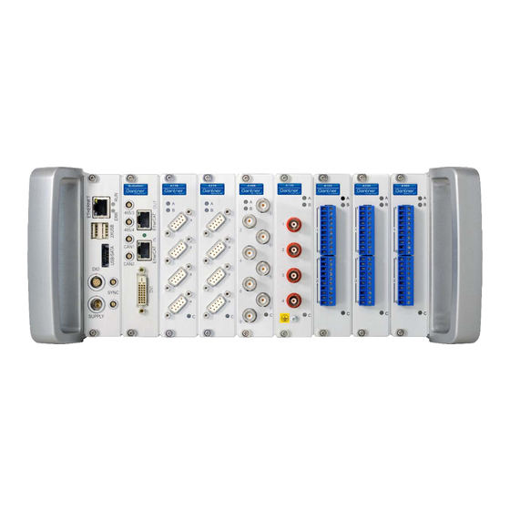
Description ................................................................................................................................ 5
Assembling the Modules ........................................................................................................... 7
DIP Switch Configuration ........................................................................................................ 12
Power Supply .............................................................................................................................. 15
Sensor Connections .................................................................................................................... 16
Standard Terminal Blocks ....................................................................................................... 16
Special Connectors ................................................................................................................. 16
Special Terminal Blocks .......................................................................................................... 17
Synchronizing Multiple Q.brixx Controllers ................................................................................. 18
Q.brixx Controllers ...................................................................................................................... 19
Connections ............................................................................................................................ 19
System Assembly (Q.brixx2) .....................................................................................................21
1
Gantner Instruments Inc.
USA | China | Singapore | India | Austria | Germany | France | Sweden
1550 Hotel Circle N ∙ Suite 180 ∙ San Diego CA ∙ 92108 ∙ T +1 888 ∙ 512 ∙ 5788
info.us@gantner-instruments.com
www.gantner-instruments.com
Advertisement
Table of Contents

Related Manuals for Gantner Q.brixx Series


Summary of Contents for Gantner Q.brixx Series
-
Page 1: Table Of Contents
Synchronizing Multiple Q.brixx Controllers ................. 18 Q.brixx Controllers ........................19 Connections ..........................19 System Assembly (Q.brixx2) .....................21 Gantner Instruments Inc. info.us@gantner-instruments.com USA | China | Singapore | India | Austria | Germany | France | Sweden www.gantner-instruments.com 1550 Hotel Circle N ∙ Suite 180 ∙ San Diego CA ∙ 92108 ∙ T +1 888 ∙ 512 ∙ 5788... - Page 2 System Check ......................... 70 Viewing & Saving Live Data ......................72 Exporting Projects ........................75 Contact Information ........................77 Gantner Instruments Inc. info.us@gantner-instruments.com USA | China | Singapore | India | Austria | Germany | France | Sweden www.gantner-instruments.com 1550 Hotel Circle N ∙ Suite 180 ∙ San Diego CA ∙ 92108 ∙ T +1 888 ∙ 512 ∙ 5788...
- Page 3 All trademarks and brand names used in this document only indicate the respective product or the proprietor of the trademark or brand name. The naming of products which are not from Gantner Instruments Inc. makes no claims on trademarks or brand names other than its own.
-
Page 4: System Preparation
ICP100, which is included with every copy of test.commander is used to perform the channel configuration in every measurement module. Other Gantner software tools not discussed within this guide can be explained on a project by project basis. Contact us today! Software Downloads test.commander:... -
Page 5: System Assembly (Q.brixx 1)
The base of each module attaches to the main body of each module using 2 x Torx T10 screws. Gantner Instruments Inc. info.us@gantner-instruments.com USA | China | Singapore | India | Austria | Germany | France | Sweden www.gantner-instruments.com... - Page 6 2. The bases are connected together and the main body of each module interlocks together. 3. Each Q.brixx system also includes 2 x side pieces/handles (left side and right side). Gantner Instruments Inc. info.us@gantner-instruments.com USA | China | Singapore | India | Austria | Germany | France | Sweden www.gantner-instruments.com...
-
Page 7: Assembling The Modules
1. Connect the handles and bases together. Start from the left side handle and move left to right. The right side handle will be secured last. Gantner Instruments Inc. info.us@gantner-instruments.com USA | China | Singapore | India | Austria | Germany | France | Sweden www.gantner-instruments.com... - Page 8 3. Connect all the bases together one by one, moving left to right. 4. Secure the bases together using a 2.5 mm Allen wrench. Gantner Instruments Inc. info.us@gantner-instruments.com USA | China | Singapore | India | Austria | Germany | France | Sweden www.gantner-instruments.com...
- Page 9 6. Before securing the controller and measurement modules onto their bases, make sure to configure the DIP switches on the bases. Please refer to the configuration section below for more details. Gantner Instruments Inc. info.us@gantner-instruments.com USA | China | Singapore | India | Austria | Germany | France | Sweden www.gantner-instruments.com...
- Page 10 7. Starting from left to right, secure the controller and measurement modules onto their bases. 8. All the modules interlock together. Gantner Instruments Inc. info.us@gantner-instruments.com USA | China | Singapore | India | Austria | Germany | France | Sweden www.gantner-instruments.com...
- Page 11 9. Secure each module onto the base from the bottom. There are 2 x Torx T10 screws for each module. 10. Reverse the procedure to disassemble or replace any modules. Gantner Instruments Inc. info.us@gantner-instruments.com USA | China | Singapore | India | Austria | Germany | France | Sweden www.gantner-instruments.com...
-
Page 12: Dip Switch Configuration
3. The 10-pin switch is used to set the address and/or terminating resistances. PINs 1-6: Sets the address of the module (binary) Gantner Instruments Inc. info.us@gantner-instruments.com USA | China | Singapore | India | Austria | Germany | France | Sweden www.gantner-instruments.com... - Page 13 UART 1: PIN 1 and 2 Up (PIN 3 and 4 Down) UART 2: PIN 3 and 4 Up (PIN 1 and 2 Down) Gantner Instruments Inc. info.us@gantner-instruments.com USA | China | Singapore | India | Austria | Germany | France | Sweden www.gantner-instruments.com...
- Page 14 11010000 00110000 10110000 01110000 Gantner Instruments Inc. info.us@gantner-instruments.com USA | China | Singapore | India | Austria | Germany | France | Sweden www.gantner-instruments.com 1550 Hotel Circle N ∙ Suite 180 ∙ San Diego CA ∙ 92108 ∙ T +1 888 ∙ 512 ∙ 5788...
-
Page 15: Power Supply
Key: 1 = UP , 0 = DOWN POWER SUPPLY Similar to other Gantner systems, the Q.brixx system requires 10-30 VDC. This is delivered via the LEMO plug located on the front of the test controller. Each Q.brixx controller from the factory is shipped with an AC to DC adapter and power cable. -
Page 16: Sensor Connections
Special Connectors The PIN connections for any special connections (DB9, BNC, mini TC, etc.) are available in the Q.brixx Manual. Gantner Instruments Inc. info.us@gantner-instruments.com USA | China | Singapore | India | Austria | Germany | France | Sweden www.gantner-instruments.com... -
Page 17: Special Terminal Blocks
• A107-CJC • A107-B4/120 • A107-B4/350 • A108-SR Gantner Instruments Inc. info.us@gantner-instruments.com USA | China | Singapore | India | Austria | Germany | France | Sweden www.gantner-instruments.com 1550 Hotel Circle N ∙ Suite 180 ∙ San Diego CA ∙ 92108 ∙ T +1 888 ∙ 512 ∙ 5788... -
Page 18: Synchronizing Multiple Q.brixx Controllers
LEMO connectors at both ends. The LEMO connector is part # FGG.00.302.CLAD30Z. The maximum length of all synchronization lines combined can be 1000 meters. Gantner Instruments Inc. info.us@gantner-instruments.com USA | China | Singapore | India | Austria | Germany | France | Sweden www.gantner-instruments.com... -
Page 19: Q.brixx Controllers
Connection Vp = 5 Volts TxD-P TxD-N Gantner Instruments Inc. info.us@gantner-instruments.com USA | China | Singapore | India | Austria | Germany | France | Sweden www.gantner-instruments.com 1550 Hotel Circle N ∙ Suite 180 ∙ San Diego CA ∙ 92108 ∙ T +1 888 ∙ 512 ∙ 5788... - Page 20 • CAN port: Used to connect to H and L of the CAN interface. This connection uses the same hardware as the UART and SYNC lines. Gantner Instruments Inc. info.us@gantner-instruments.com USA | China | Singapore | India | Austria | Germany | France | Sweden www.gantner-instruments.com...
-
Page 21: System Assembly (Q.brixx2)
2. The complete Q.brixx system includes a left side and right side handle. Detach the right side handle to remove or add modules. Gantner Instruments Inc. info.us@gantner-instruments.com USA | China | Singapore | India | Austria | Germany | France | Sweden www.gantner-instruments.com... - Page 22 5. After the last base has been secured, connect the right side handle using the 2 x hex screws. Tighten the screws using a 3 mm hex key. Gantner Instruments Inc. info.us@gantner-instruments.com USA | China | Singapore | India | Austria | Germany | France | Sweden www.gantner-instruments.com...
- Page 23 7. All the modules including the controller are secured to the base using 2 x long hex screws. Tighten the screws using a Torx T10 screw driver. Gantner Instruments Inc. info.us@gantner-instruments.com USA | China | Singapore | India | Austria | Germany | France | Sweden www.gantner-instruments.com...
-
Page 24: Pc Configuration
Gantner Instruments test controller. 1. Firewall – Provide exceptions for Gantner Instruments software tools 2. IP Address Configuration – If the Gantner system and PC are connected to the same network via a switch or router, the Gantner controller will obtain an IP address automatically using DHCP. -
Page 25: Firewall
• SetupAssistant IP Address 1. If the PC and Gantner system are connected to the same network, the PC and Gantner system will each obtain an IP address automatically (i.e. DHCP). By default, a Gantner test controller has DHCP enabled. - Page 26 6. Under the Networking tab, double-click on Internet Protocol Version 4 (TCP/IPv4). 7. Within the TCP/IPv4 Properties window, give the PC a static IP address on the same network as the Gantner controller (i.e. 192.168.1.20) and a Subnet mask of 255.255.255.0 Gantner Instruments Inc.
-
Page 27: Starting Test.commander
LICENSED mode. Enter the license information into the window provided: 3. When the license is entered successfully, the program will change to licensed mode. Gantner Instruments Inc. info.us@gantner-instruments.com USA | China | Singapore | India | Austria | Germany | France | Sweden www.gantner-instruments.com... - Page 28 5. Language settings may need to be set. Extras > Settings, navigate to Language: 6. Select File > New Project. Gantner Instruments Inc. info.us@gantner-instruments.com USA | China | Singapore | India | Austria | Germany | France | Sweden www.gantner-instruments.com...
-
Page 29: Slave Setup
2. With a blank project open, select Utilities > Slave Setup Assistant: Gantner Instruments Inc. info.us@gantner-instruments.com USA | China | Singapore | India | Austria | Germany | France | Sweden www.gantner-instruments.com... - Page 30 Q.brixx 3. The Slave Setup Assistant window will appear. Click on the perform Scan button to search for the attached controller. Gantner Instruments Inc. info.us@gantner-instruments.com USA | China | Singapore | India | Austria | Germany | France | Sweden www.gantner-instruments.com...
- Page 31 5. The program will scan all UARTs (2 on a Q.gate and 4 on a Q.station/Q.pac) to search for all connected measurement modules. All modules that are found will be displayed in the Slave Setup Assistant window: Gantner Instruments Inc. info.us@gantner-instruments.com USA | China | Singapore | India | Austria | Germany | France | Sweden www.gantner-instruments.com...
-
Page 32: Firmware Updates
7. Click the write Changes button to apply the new settings. Firmware Updates 1. New Gantner hardware (controllers and measurement modules) are shipped from the factory with the most up to date version of the firmware loaded. However, it is good practice to verify if the system has the most current firmware version from time to time. - Page 33 OK button. 4. The Controller Update Tool appears, highlight the controller to update and click the Update button. Gantner Instruments Inc. info.us@gantner-instruments.com USA | China | Singapore | India | Austria | Germany | France | Sweden www.gantner-instruments.com...
- Page 34 Ethernet cable during the update process. 7. To check the firmware version of a measurement module, select Utilities > Slave Firmware Update: Gantner Instruments Inc. info.us@gantner-instruments.com USA | China | Singapore | India | Austria | Germany | France | Sweden www.gantner-instruments.com...
- Page 35 8. The Slave Firmware Update window appears, click the perform Scan button. 9. Highlight the controller to connect to and click the OK button. Gantner Instruments Inc. info.us@gantner-instruments.com USA | China | Singapore | India | Austria | Germany | France | Sweden www.gantner-instruments.com...
-
Page 36: Connecting To The Hardware
1. Within the blank project, right-click on the mouse and select Add Online Controllers. 2. Select the controller to add to the project and click the OK button. Gantner Instruments Inc. info.us@gantner-instruments.com USA | China | Singapore | India | Austria | Germany | France | Sweden www.gantner-instruments.com... - Page 37 4. The following window appears at the end of the process, click OK. 5. The controller and connected measurement modules are shown in the project. Gantner Instruments Inc. info.us@gantner-instruments.com USA | China | Singapore | India | Austria | Germany | France | Sweden www.gantner-instruments.com...
-
Page 38: Configuring A Controller
The 2 , and 4 sample rate can be the same or less as the 1 sample rate. Gantner Instruments Inc. info.us@gantner-instruments.com USA | China | Singapore | India | Austria | Germany | France | Sweden www.gantner-instruments.com... - Page 39 Q.station. Gantner Instruments Inc. info.us@gantner-instruments.com USA | China | Singapore | India | Austria | Germany | France | Sweden www.gantner-instruments.com...
-
Page 40: Controller's Sample Rate (Q.gate)
There is 16 MB available between all buffers. 2. Navigate to Settings > Synchronization. The Sync. sample frequency can be modified: Gantner Instruments Inc. info.us@gantner-instruments.com USA | China | Singapore | India | Austria | Germany | France | Sweden www.gantner-instruments.com... - Page 41 ����������������. �������������������� ���� ������������������������������������ ≤ 1000 �������� # �������� �������������������������������������������� ���� ������������ �������� ���� �������� ���� ���� ������������������������ Gantner Instruments Inc. info.us@gantner-instruments.com USA | China | Singapore | India | Austria | Germany | France | Sweden www.gantner-instruments.com...
-
Page 42: Pac Functionality Activation/Deactivation
The test.con program is saved to this memory. 4. Creating and downloading a test.con program into a Gantner test controller will be explained in further detail in out test.con quick start guide. Gantner Instruments Inc. -
Page 43: Uart Configuration
Q.station: Q.gate: The 2 UART of a Q.gate can be configured to use the Modbus protocol. Gantner Instruments Inc. info.us@gantner-instruments.com USA | China | Singapore | India | Austria | Germany | France | Sweden www.gantner-instruments.com 1550 Hotel Circle N ∙ Suite 180 ∙ San Diego CA ∙ 92108 ∙ T +1 888 ∙ 512 ∙ 5788... -
Page 44: Life Signal (Q.station Only)
The conditions can be switched on/off and can be combined as either AND/OR logic. To modify these settings, double-click on the Q.station and navigate to Settings > Life signal. Gantner Instruments Inc. info.us@gantner-instruments.com USA | China | Singapore | India | Austria | Germany | France | Sweden www.gantner-instruments.com... -
Page 45: Interfaces (Q.station)
Configuring these interfaces can be found by double-clicking on the Q.station and navigating to Host interface: More information about how to utilize and apply these interfaces can be found on separate start-up guides on the Gantner website. Synchronization Source The controller can obtain its synchronization internally (built-in real time clock) or externally (via SNTP, IRIG, GPS, AFNOR, or another Q.series controller). - Page 46 Host Interface > SNTP > Client Settings. Change the SNTP mode from Off to On. Enter the IP address of the location of the SNTP server. More information can be found in the “Synchronization via SNTP” guide on the Gantner website. To synchronize the controller to another controller, set the Input Synchronization Protocol to Q.sync over RS485.
- Page 47 “Synchronize” button to apply the synch. Time – date and time of the PC. Device – date and time of the controller. Gantner Instruments Inc. info.us@gantner-instruments.com USA | China | Singapore | India | Austria | Germany | France | Sweden www.gantner-instruments.com...
-
Page 48: Channel Configuration
3. Type: this column selects the type of variable (varies by module type). A real variable is an AI (Analog Input), AO (Analog Output), DI (Digital Input), or DO (Digital Output). Gantner Instruments Inc. info.us@gantner-instruments.com USA | China | Singapore | India | Austria | Germany | France | Sweden www.gantner-instruments.com... - Page 49 For example, a thermocouple can be factory calibrated. Highlight the sensor to modify and click on the Copy button. Gantner Instruments Inc. info.us@gantner-instruments.com USA | China | Singapore | India | Austria | Germany | France | Sweden www.gantner-instruments.com...
- Page 50 Edit button. The sensor configuration window appears. This window provides more information about the pre-configured sensor. Click on the Lineariz. button. Gantner Instruments Inc. info.us@gantner-instruments.com USA | China | Singapore | India | Austria | Germany | France | Sweden www.gantner-instruments.com...
- Page 51 The table can be exported and modified in a spreadsheet by clicking the Export button. A modified table can be imported by clicking on the Import button. Gantner Instruments Inc. info.us@gantner-instruments.com USA | China | Singapore | India | Austria | Germany | France | Sweden www.gantner-instruments.com...
- Page 52 In the example below, the voltage sensor is wired across PINs 3 and 7. 8. Terminals: this column specifies which connector to use on the measurement module. Each Gantner measurement modules has 2 x connectors (a top and bottom). The top is connector 1 and the bottom is connector 2.
- Page 53 The variable can be scaled using either of 2 x methods: point-point calibration or factory/offset. For this example we will use the point-point calibration method. Gantner Instruments Inc. info.us@gantner-instruments.com USA | China | Singapore | India | Austria | Germany | France | Sweden www.gantner-instruments.com...
- Page 54 Zeroing and Taring are also configured in this section. A separate quick start guide that discusses how to apply the zero and tare feature can be found on the Gantner Instruments website: LINK 10. Range/Error: this column sets the minimum and maximum value to display. A value not within this range will result in an error/sensor failure.
-
Page 55: Virtual Variables
They can also be created inside the controller under the virtual variables section. Inside the Measurement Module Gantner Instruments Inc. info.us@gantner-instruments.com USA | China | Singapore | India | Austria | Germany | France | Sweden www.gantner-instruments.com... - Page 56 Each alarm can have up to 4 x separate conditions that are combined as logical OR. The conditions to select from are shown below: Gantner Instruments Inc. info.us@gantner-instruments.com USA | China | Singapore | India | Austria | Germany | France | Sweden www.gantner-instruments.com...
- Page 57 Additionals column. For example, the formula for an arithmetic variable can be created. 5. Make sure to save the configuration before closing ICP100. Gantner Instruments Inc. info.us@gantner-instruments.com USA | China | Singapore | India | Austria | Germany | France | Sweden www.gantner-instruments.com...
- Page 58 Inside the Test Controller 1. The Virtual Variables section is available under the test controller. Right-click on this section to add a new variable. Gantner Instruments Inc. info.us@gantner-instruments.com USA | China | Singapore | India | Austria | Germany | France | Sweden www.gantner-instruments.com...
- Page 59 (i.e. average, min/max, comparison, PID). Any variable (real or virtual) within the same controller can be used within the arithmetic. Gantner Instruments Inc. info.us@gantner-instruments.com USA | China | Singapore | India | Austria | Germany | France | Sweden www.gantner-instruments.com...
- Page 60 CAN data base file is available, the pre-defined variables can be selected from this file; click the CAN DB button to navigate to the file. Gantner Instruments Inc. info.us@gantner-instruments.com USA | China | Singapore | India | Austria | Germany | France | Sweden www.gantner-instruments.com...
-
Page 61: Naming Variables In Batches
(Volts 1, Volts 2, …, Volts 20, etc.). Gantner Instruments Inc. info.us@gantner-instruments.com USA | China | Singapore | India | Austria | Germany | France | Sweden www.gantner-instruments.com... - Page 62 2. Select the Variable Names option. 3. Click on the Add new rule button. 4. Give the rule a name. Gantner Instruments Inc. info.us@gantner-instruments.com USA | China | Singapore | India | Austria | Germany | France | Sweden www.gantner-instruments.com...
- Page 63 5. Define the variable’s format in the Rule string section. 6. Use the pre-set rules to create the custom string. For example: Gantner Instruments Inc. info.us@gantner-instruments.com USA | China | Singapore | India | Austria | Germany | France | Sweden www.gantner-instruments.com...
- Page 64 10. It is possible to auto assign names using the pre-set methods (UART/ADDRESS/VARIABLE or TYPE/INFO) or using one of the rules we created. Gantner Instruments Inc. info.us@gantner-instruments.com USA | China | Singapore | India | Austria | Germany | France | Sweden www.gantner-instruments.com...
- Page 65 11. Click the OK button to apply the new settings. The variables have been renamed in the project, make sure to update the project to the controller to finalize the process Gantner Instruments Inc. info.us@gantner-instruments.com USA | China | Singapore | India | Austria | Germany | France | Sweden www.gantner-instruments.com...
-
Page 66: Data Logger Configuration - Q.station
UART can be configured for 1 x data buffer (i.e. 1 x sample rate). Modules/channels under a single UART can’t be split into more than 1 x data buffer. Incorrect: Gantner Instruments Inc. info.us@gantner-instruments.com USA | China | Singapore | India | Austria | Germany | France | Sweden www.gantner-instruments.com... -
Page 67: Sample Rate Assignment
1. Configure the number of data buffers to create. Double-click on the Q.station and navigate to Sample rate > Count. Enter the number of sample rates (1 to 4). Gantner Instruments Inc. info.us@gantner-instruments.com USA | China | Singapore | India | Austria | Germany | France | Sweden www.gantner-instruments.com... - Page 68 4. Additional settings become available when set to external. Please see pages 60-61 and 85 of the Q.station manual for more details. Gantner Instruments Inc. info.us@gantner-instruments.com USA | China | Singapore | India | Austria | Germany | France | Sweden www.gantner-instruments.com...
-
Page 69: Apply Sample Rate To Measurement Modules
Q.bloxx A107 (2/1) = Q.bloxx A101 (UART 2/Address 1) Accessing Logger Configuration The preliminary settings are now configured. Highlight the Q.station and click the Logger configuration button. Gantner Instruments Inc. info.us@gantner-instruments.com USA | China | Singapore | India | Austria | Germany | France | Sweden www.gantner-instruments.com... -
Page 70: Project Verification
Select the Calculate Statistics button. Select the Check button. The Design Rule Check window will appear. The back ground color displays the feasibility: Gantner Instruments Inc. info.us@gantner-instruments.com USA | China | Singapore | India | Austria | Germany | France | Sweden www.gantner-instruments.com... - Page 71 Q.uick Start Guide Q.brixx White = Will work Red = Will not work Gantner Instruments Inc. info.us@gantner-instruments.com USA | China | Singapore | India | Austria | Germany | France | Sweden www.gantner-instruments.com 1550 Hotel Circle N ∙ Suite 180 ∙ San Diego CA ∙ 92108 ∙ T +1 888 ∙ 512 ∙ 5788...
-
Page 72: Viewing & Saving Live Data
This is performed using the built-in tool called test.viewer. Select the Read Online Values From Controller button: Gantner Instruments Inc. info.us@gantner-instruments.com USA | China | Singapore | India | Austria | Germany | France | Sweden www.gantner-instruments.com... - Page 73 Check if there are any data dropouts (if there are any error counters accruing). Click on the Show online graph button to open test.viewer. Gantner Instruments Inc. info.us@gantner-instruments.com USA | China | Singapore | India | Austria | Germany | France | Sweden www.gantner-instruments.com...
- Page 74 Live Stream. Select File > Save As. Select a name for the file and the format in which to save to. Gantner Instruments Inc. info.us@gantner-instruments.com USA | China | Singapore | India | Austria | Germany | France | Sweden www.gantner-instruments.com...
-
Page 75: Exporting Projects
Q.uick Start Guide Q.brixx EXPORTING PROJECTS The test.commander project is saved in the projects folder within the Gantner directory of the PC. When the project is updated to the controller, it is also saved inside the controller. To modify the project on a different PC: 1. - Page 76 Q.uick Start Guide Q.brixx 2. Give the ZIP file a name and click Save. Gantner Instruments Inc. info.us@gantner-instruments.com USA | China | Singapore | India | Austria | Germany | France | Sweden www.gantner-instruments.com 1550 Hotel Circle N ∙ Suite 180 ∙ San Diego CA ∙ 92108 ∙ T +1 888 ∙ 512 ∙ 5788...
-
Page 77: Contact Information
6780 Schruns / Austria Ph: +43 (0) 5556 77463-0 Fax: +43 (0) 5556 77463-300 Email: office@gantner-instruments.com Web: www.gantner-instruments.com Germany Gantner Instruments Test & Measurement GmbH Heidelberger Landstr. 74 64297 Darmstadt / Germany Ph: +49 6151 95136-0 Fax: +49 6151 95136-26 Email: testing@gantner-instruments.com Web: www.gantner-instruments.com...
Need help?
Do you have a question about the Q.brixx Series and is the answer not in the manual?
Questions and answers