Advertisement
Table of Contents
- 1 Table of Contents
- 2 Introduction
- 3 Configurable Features
- 4 Standard Features
- 5 Dip Switch Features
- 6 Unpacking & Pre-Installation
- 7 Installation & Mounting
- 8 Amplifier Power Distribution
- 9 Troubleshooting
- 10 Siren Wiring Diagram
- 11 Siren Specifications
- 12 Lighting Specifications
- 13 Siren Control Head - Exploded View
- 14 Warranty
- Download this manual
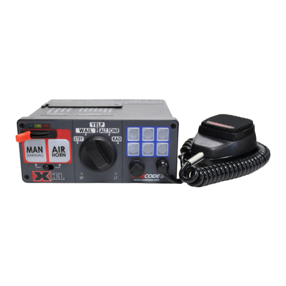
XCEL SERIES
SIREN
PATENTED. See https://secure.code3pse.com/patents/
WARNING
Sirens produce loud sounds that may damage hearing
•
Wear hearing protection when testing
•
Use siren only for emergency response
•
Roll up windows when siren is operating
•
Avoid exposure to the siren sound outside of vehicle
Read all instruction and warnings before installing and using.
IMPORTANT:
INSTALLER:
TM
This manual must be delivered to the end user of this equipment.
1
Contents:
Introduction............................................................................2
Configurable Features.........................................................2-3
Standard Features................................................................3-5
Dip Switch Features................................................................6
Unpacking & Pre-installation..................................................7
Installation & Mounting............................................................7
Amplifier Power Distribution.................................................8
Troubleshooting..................................................................9
Siren Wiring Diagram.............................................................10
Siren Specifications..............................................................11
Lighting Specifications........................................................11
Siren Control Head - Exploded View.......................................12
Siren Control Head - Parts List................................................13
Notes................................................................................14-15
Warranty................................................................................16
Advertisement
Table of Contents

Related Manuals for Code 3 XCEL Series


Summary of Contents for Code 3 XCEL Series
-
Page 1: Table Of Contents
XCEL SERIES SIREN Contents: Introduction................2 Configurable Features............2-3 Standard Features..............3-5 Dip Switch Features..............6 Unpacking & Pre-installation..........7 Installation & Mounting............7 Amplifier Power Distribution..........8 Troubleshooting..............9 Siren Wiring Diagram.............10 Siren Specifications..............11 PATENTED. See https://secure.code3pse.com/patents/ Lighting Specifications............11 Siren Control Head - Exploded View........12 Siren Control Head - Parts List..........13 Notes................14-15... -
Page 2: Introduction
Introduction The XCEL Siren has been designed to meet the needs of all emergency vehicles. It incorporates many of the popular features of the past and uses microprocessor based circuitry. All standard features are available along with many new features: Fully Configurable 3-Level Switch, Selectable Tones, Adjustable Backlighting, Hands Free and much more. - Page 3 To enter into Programming Mode, follow the following instructions: Move Level Switch to Level 0 (furthest to the left) Turn all Auxiliary Switches off Move Rotary Knob to RAD (Radio) Press and hold MAN (Manual) button for at least 2 seconds (at this point the Auxiliary Button backlighting indication will turn RED) , then release.
- Page 4 Standard Features- Cont: ALT TONE Rotary Knob - This position produces either Hi-Lo or Hyper-Yelp dependent on Dip Switch 12. Operation of this feature is affected by SirenLock, 3-Level Switch, Park Kill, and Title 13 features. See these sections for details. Radio (RRB) - This position operates Radio ReBroadcast over siren speakers.
- Page 5 Standard Features- Cont: SirenLock - SirenLock is used to allow the XCEL Siren to only generate the tones when in Level 3. When SirenLock is enabled, the XCEL Siren is ‘Locked’ from generating Primary tones until the 3-Level Switch is moved to Level 3. SirenLock does not affect the MANUAL and AIR HORN push- buttons.
-
Page 7: Unpacking & Pre-Installation
(see Figure 2). Also reference page 12 and 13 for description of components and Code 3 part numbers. Ease of operation and convenience to the operator should be the prime consideration when mounting the siren and controls. When... -
Page 8: Amplifier Power Distribution
Connection of a 58 watt speaker to the siren amplifier will cause the speaker to burn out, and will void the speaker WARNING warranty! Amplifier Power Distribution The Level 1, 2, 3A and 3B outputs can supply a maximum of 15 Amps each or a combined total of 50 Amps. Each Level has a 20 Amp fuse installed inside the Amplifier. -
Page 9: Troubleshooting
B. PLUG MICROPHONE IN SECURELY C. DEFECTIVE MICROPHONE C. REPLACE MICROPHONE D. INCORRECT MICROPHONE. D. CALL CODE 3 FOR LIST OF ADAPTABLE MICROPHONES. RRB VOLUME LOW, OR NO RRB AT ALL. A. INCREASE RADIO REBROADCAST A. REFER TO SETUP AND ADJUSTMENT VOLUME. -
Page 11: Siren Specifications
Siren Specifications Siren Section: Input Voltage 10 to 16 VDC and ground - 12V units (Note: Operation of 12V units above 15 VDC for an extended period of time may result in speaker damage.) Operating Current 100W: 8 Amps @ 13.6V with 11-ohm load (100 Watt Speaker) - 12V units 200W: 14 Amps @ 13.6V with 5.5-ohm load (2-100 Watt Speakers) - 12V units (NOTE: There is no 58 Watt speaker connection available.) Standby Current... -
Page 12: Siren Control Head - Exploded View
*Code 3®, Inc. reserves the right to repair or replace at its discretion. Code 3®, Inc. assumes no responsibility or liability for expenses incurred for the removal and /or reinstallation of products requiring service and/or repair; nor for the packaging, handling, and shipping: nor for the handling of products returned to sender after the service has been rendered.
Need help?
Do you have a question about the XCEL Series and is the answer not in the manual?
Questions and answers