Avlite AV-70 Installation & Service Manual
Solar aviation light icao, faa l861t and casa
Hide thumbs
Also See for AV-70:
- Manual (16 pages) ,
- Installation & service manual (28 pages) ,
- Quick start manual (2 pages)

Related Manuals for Avlite AV-70


Summary of Contents for Avlite AV-70
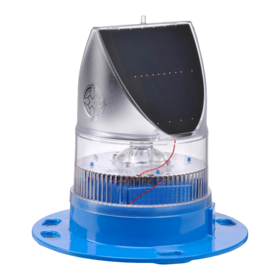
- Page 1 AV-70 Solar Aviation Light ICAO, FAA L861T and CASA INSTALLATION & SERVICE MANUAL V6.0...
- Page 2 Version No. Description Date Reviewed Approved Design AV-426 Manual Launch June 2019 P. Naidu W. Evans M. Sugars...
-
Page 3: Table Of Contents
3.1 AV-70 - Data Sheet ................................8 Installation ..........................10 4.1 Selecting Power Intensity .............................12 4.2 Selecting a Flash Code - Rotary Switch A and B (AV-70 and AV-70-HI).........13 4.3 Flash Codes ..................................13 4.4 Installing the Light Assembly ............................18 4.5 Manual Light Activation via Momentary Button ...................23 Avlite Radio Controller ......................24... -
Page 4: Introduction
1.0 Introduction Congratulations! By choosing to purchase an Avlite light, you have become the owner of one of the most advanced solar LED airfield lights in the world. Avlite Systems draws on more than 25 years experience in the design and manufacture of navigation aids, and particular care has been taken to ensure your light gives years of trouble free service. -
Page 5: Technology
LED Technology All Avlite lights use the latest advancements in LED (Light Emitting Diode) technology as a light source. The major advantage of LED’s over traditional light sources is well established in that they typically have an operational life in excess of 100,000 hours, resulting in substantial savings to maintenance and servicing costs. -
Page 6: Models L861, Icao
The battery is protected from over-charging within the circuit to ensure maximum battery life. The AV-70-HI is a high intensity version of the popular AV-70 and is ideal for use in high sunlight areas that receive a minimum of 3.5 hours of sun per day. - Page 7 Automatic night activation LED aviation lens with 0 to +7° vertical divergence Tough UV-stabilised LEXAN® polycarbonate Band of colour lens and light base identification tape User-replaceable battery in sealed compartment Latest products and information available at www.avlite.com...
-
Page 8: Data Sheet
3.1 AV-70 - Data Sheet AV-70 AV-70-HI AV-70-RF Light Characteristics Light Source Available colours Red, Green, White, Yellow, Blue Horizontal Output (degrees) Vertical Divergence (degrees) 0 to +7 Red - 12 Red - 17.4 Red - 12 Green - 11... - Page 9 LED Colour Standard (Engineering Brief No. 67D) CASA MOS Part 139, Volume 2, 2016, Section Other regulations 9.13.15 DGAC (Mexico) Intellectual Property AVLITE is a registered trademark of Avlite Systems ® Trademarks Patents Pending Warranty * 3 year warranty • Manual Operation • Radio Controlled •...
-
Page 10: Installation
Please contact your Avlite office if there is any hardware missing. Initial Inspection Inspect all hardware for damage. If there is any damage, please contact your Avlite Office. Retain original packing material for possible future use in shipping the AV-70. - Page 11 NOTE: Before activating the lights, the lights must be layed out on the runway in the location they will be installed. • NOTE: RF lights should always be installed on mounting plates and stakes. Avlite does not recommend installation on rubber tiles. Use a large flat-blade screwdriver to remove the Flash Adjustment Plug from the base of the light (see Figure 1).
-
Page 12: Selecting Power Intensity
4.1 Selecting an Intensity/Power Setting - AV-70 and AV-70-HI Intensity/power settings on Avlite lanterns operate via DIP switches, located near the rotary switches on the flasher unit. The intensity/power settings may be used to reduce the power consumption and intensity of the lantern. Setting the lantern to 25% intensity will reduce the power consumption to 25% of the normal 100% setting and the range by 25%. -
Page 13: Selecting A Flash Code - Rotary Switch A And B (Av-70 And Av-70-Hi)
It is best to operate at the lowest duty cycle appropriate to the actual needs of the application. Please note, Avlite models will retain full autonomy in normal operating conditions with duty cycles up to approximately 30%. In applications whereby duty cycles exceed this limit, a reduction in light intensity is recommended. - Page 14 SWITCH FLASH CODE SWITCH FLASH CODE F (Steady light) FL 5 S VQ 0.5 S ISO 5 S VQ 0.6 S LFL 5 S VQ 0.6 S OC 5 S Q 1 S OC 5 S Q 1 S OC 5 S Q 1 S FL 6 S Q 1 S...
- Page 15 15.0 FL (2) 25 S 22.0 SWITCH FLASH CODE Q (3) 5 S VQ (3) 5 S VQ (3) 5 S VQ (3) 5 S FL (3) 6 S FL (2+1) 6 S Latest products and information available at www.avlite.com...
- Page 16 SWITCH FLASH CODE Q (3) 6 S FL (3) 8 S FL (3) 9 S FL (3) 9 S FL (3) 10 S FL (3) 10 S FL (3) 10 S FL (3) 10 S FL (3) 10 S FL (3) 10 S FL (2+1) 10 S OC (3) 10 S Q (3) 10 S...
- Page 17 MO (A) 10 S MO (D) 10 S MO (A) 15 S 11.0 MO (U) 15 S 11.8 MO (U) 15 S 10.7 MO (U) 15 S 10.1 MO (B) 15 S 10.5 Latest products and information available at www.avlite.com...
-
Page 18: Installing The Light Assembly
(within the triangular recess). It may be necessary to use a rubber mallet to insert the bolts. Fit the AV-70 light over the bolts on the top face of the tile. (It is possible to align the lens ridge with the sides of the tile, but this is not a requirement). - Page 19 Fit the AV-70 light on the top of the mounting plate. Insert bolts through the four holes in the mount, entering from the bottom. Install a penny washer and a Nylock nut on each bolt and tighten.
- Page 20 Item Description AV-70 Solar Airfield Light Mount Plate Frangible Sleeve Stake (355mm) Bolt, 8mm x 30 Penny Washer, 8mm Nylock Nut, 8mm Socket Head Cap Screw, 8mm x 16 Allen Key, 6mm...
- Page 21 - Fit the frangible coupling and top mounting plate and using a level check that the light mounting plate is level using a spirit level. d. Fit the AV-70 to the light mounting plate using M8 SHCS, large flat washers and Nylock nuts.
- Page 22 Item Description AV-70 Solar Airfield Light Mount Plate Frangible Sleeve Bolt, 8mm x 25 Penny Washer, 8mm Nylock Nut, 8mm Socket Head Cap Screw, 8mm x 16 Allen Key, 6mm...
-
Page 23: Manual Light Activation Via Momentary Button
The AV-70-RF lights are available with optional external momentary button for manual light operation. The momentary button may be incorporated in the AV-70-RF for emergency use or in case the radio controller is lost or damaged. This button enables the user to manually turn the light on and step through the three different intensity levels. -
Page 24: Avlite Radio Controller
The unit allows for easy activation, inspection and testing of the airfield lights. The Avlite Radio Controller works on the 2.4GHz ISM Band using a low power RF module. The backlit, LCD can be seen during day or night. The straightforward menu provides ease of operation. -
Page 25: Assembly And Installation Of Radio Controller
Please contact your Avlite office if there is any hardware missing. Initial inspection Inspect the Radio Controller for damage. If there is any damage, please contact your Avlite office. Retain original packing material for possible future use. Assembly & Charging The Radio Controller can be activated after raising the aerial into the upright position, see Fig 5. -
Page 26: Radio Controller Menu
5.2 Radio Controller Menu This section of the document will provide a short explanation of all the menu screens on the control unit. Operation Mode The Operation Mode defines how the light will respond to different environmental conditions & user inputs. There are three operational modes that can be selected via the controller;... - Page 27 EXTERNAL POWER: Checks for external power connection. (1 x 1 second flash) (2 x 300 milli second flashes) *For more information regarding the Yes/No flash response, please see section 5.1.7 of the AvMesh RF Communications Manual. Latest products and information available at www.avlite.com...
-
Page 28: Using The Radio Control To Activate The Airfield Lighting System (Als)
5.3 Using the Radio Control to Activate the Airfield Lighting System The Radio Controller is very easy to use and by reading through the How To section below, all of the advanced features will be well within your grasp. Make sure that all the lights in the same Light Group have had the rotary switches set correctly. - Page 29 Press [SEND] button Runway A will be in LOW Intensity IR mode Runway B will not change state. Lights on Runway B will still receive and pass on the message intended for Runway A. Latest products and information available at www.avlite.com...
-
Page 30: Maintenance And Servicing
To test place dark cover (towel or jacket) on top of light to activate sensor, light will come on. For the AV-70-RF, the remote control will need to be used to test the operation of the light. (see ‘5.3 Using the Radio Control to activate the Airfield Lighting System’... - Page 31 Installation & Service Manual Long Term Storage Instructions If the AV-70 is to be placed in storage for an extended period, being more than 5 months, please follow the below steps. The 3.6V NiMH Battery must be stored in a fully charged condition.
-
Page 32: Troubleshooting
• Ensure the Radio Controller is not always set to ALWAYS ON (see “Operation Mode” in “5.2 Radio Controller Menu” for more information). Light will not respond Refer to AvMesh RF Communications System Installation to controller in Radio and Trouble Shooting Manual, available under the AV-70 Control Mode Downloads section. - Page 33 Lantern is synchronised to surrounding lanterns. Steady On Flat Battery Battery is flat. 1/10 1/10 Low Battery Battery is low. 2/10 Factory Set. Unit is in factory setup mode (FF). Change flash code. Latest products and information available at www.avlite.com...
- Page 34 Notes...
- Page 35 AV-70 Solar Aviation Light Installation & Service Manual Latest products and information available at www.avlite.com...
- Page 36 Avlite Solution Verticals available Airfield Heliport Obstruction We believe technology improves navigation avlite.com info@avlite.com Avlite Systems Avlite USA LLC Avlite Asia Pte Ltd Australia Singapore +61 (0)3 5977 6128 +1 (603) 737 1311 +65 6908 2917...
Need help?
Do you have a question about the AV-70 and is the answer not in the manual?
Questions and answers