
Related Manuals for Sylvac D 100S


Summary of Contents for Sylvac D 100S
- Page 1 INSTRUCTIONS FOR USE Program version V1.4 December 2004 Sylvac SA Ch. du Closalet 16 CH – 1023 Crissier www.sylvac.ch...
-
Page 3: Table Of Contents
1. D100S DISPLAY UNIT ................6 1.1 GENERAL DESCRIPTION............................6 1.2 FRONT OF UNIT ..............................6 1.3 FUNCTION KEYS ..............................7 1.3.1 Summary of functions ............................7 1.3.2 General method ..............................10 1.3.3 Entering numbers :............................10 OPERATION................................10 1.5 EXAMPLES OF OPERATIONS ..........................12 1.5.1 Simple measurements : ...........................12 1.5.2 Combined measurements A +/-B (using D102 or D108) : ................12... - Page 4 1.6.15 STORE KEY..............................50 1.7 CALIBRATION OF THE UNIT ..........................52 1.7.1 General calibration ............................52 1.7.2 Coupling probe to unit ............................52 1.8 REAR PANEL ...............................54 1.8.1 RS-232-C Input/output ............................54 1.8.2 RS-232-C input instrument (Opto-RS simplex or duplex)................54 1.8.3 Outputs................................55 1.8.4 Centronics Output : parallel printer link......................56 1.8.5 Socket for mains charger ..........................57...
- Page 5 4 SYLVAC PROBES P2, P5, P10, P25 AND P50.........69 4.1 GENERAL DESCRIPTION...........................69 4.2 PROBE DIMENSIONS ............................69 USE..................................70 4.3.1 Precautions ..............................70 4.3.2 Changing the contact point ..........................70 4.4 MAINTENANCE ..............................70 4.4.1 Replacing the connection cable, for P10, P25 and P50 : ................70...
-
Page 6: D100S Display Unit
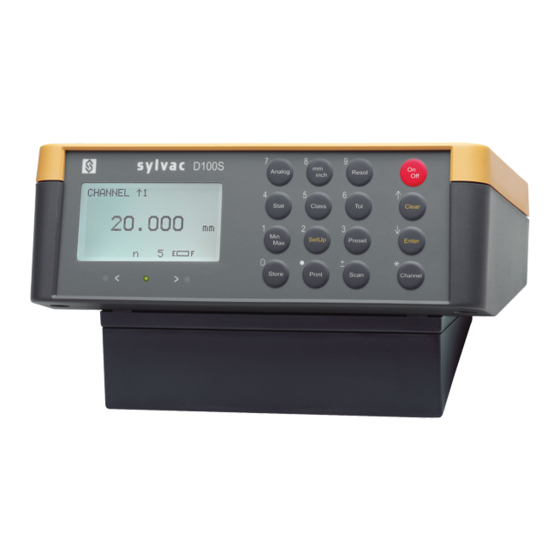
1.1 GENERAL DESCRIPTION The D100S unit displays the absolute displacement of the long-travel Sylvac probes 2, 5, 10, 25 et 50 mm (P2, P5, P10, P25 et P50). Highest resolution is 0.1 µm. It also allows for OptoRS simplex or duplex instruments to be seen. -
Page 7: Function Keys
1.3 FUNCTION KEYS 1.3.1 Summary of functions : displays or removes analog scale. : lock/unlock the mm/inch conversion. : direct conversion mm/in. : choice of the resolution : 0.1-0.01-0.001-0.0001 mm ou 0.01- 0.001-0.0001-0.00001 in : There are two choices : : displays statistical results - display classical statistics and, if of stored values. - Page 8 : introduction of general parameters: : introduction of parameters or function of the external contact, functions for the following keys. language, keyboard lock, sound Stat, Class, Tol, Clear or Enter, inhibition, date/time input and save Min/Max, Setup, Preset, Store, configurations (up to 12). Print, Scan and Channel.
- Page 9 : either proceed to preceding : choice of Enter/Clear function : channel, adjust contrast or change channel, contrast adjustment pneumatic descent. or pneumatic descent. When entering parameters : confirm numerical entry or :unlock the keyboard if inhibited. proceed to following menu. : either proceed to following : choice of Enter/Clear function : channel, adjust contrast or...
-
Page 10: General Method
1.3.2 General method All functions are directly accessible, e.g. by pressing the Tol key, tolerance indicators will be displayed. Pressing it again causes the indicators to disappear. The numbers on the function keys are used to select a menu or to enter numeric values. - Page 11 6/ Select language by pressing 2 then 2 then 3 and then 1,2 or 3 (see chap.. 1.6.11). This selection is memorized permanently by the unit (along with all other data). 7/ Where necessary, convert from metric to imperial measurement by pressing mm/inch key. 8/ Specify the readout resolution by pressing Resol key and then 1,2,3 or 4 (Section 1.6.4).
-
Page 12: Examples Of Operations
1.5 EXAMPLES OF OPERATIONS 1.5.1 Simple measurements : Choose the required channel + channel number + ENTER or if this channel was combined (A+/-B or A+/-B+/-C) Reverse measuring direction 1.5.2 Combined measurements A +/-B (using D102 or D108) Choose the measuring direction of channel 1 Choose combination 1 + 2 or 1 - 2 once = + twice = -... -
Page 13: Measurements With Classification (2 To 6 Classes)
1.5.6 Measurements with classification (2 to 6 classes) Enter number of classes and then limits of classes using Setup key and Class key. Activates or deactivates the indicators. 1.5.7 Statistics Store = mémorizing: Setup, Store, Class keys then number of Store channels. Display statistics with Stat key, choose statistics type by pressing Setup, Stat Display next tables (only available if tolerances have been activated) by pressing Enter key. -
Page 14: Function Keys
FUNCTION KEYS 1.6.1 CLEAR KEY Operating in normal move to following channel, adjust contrast or control lifting of probes with D110 measuring mode or D110V (choose between three functions by pressing Setup the Enter : (refer to next page). Operating in Min/Max mode : clears the Min/Max memory before taking a new measurement. -
Page 15: Enter Key
1.6.2 ENTER KEY Operating in normal measuring model: move directly to preceding channel, adjust contrast or controls descent of probe with D110 or D110V. Choose between following three functions : 1/ press Setup key 2/ Then press Enter key or Clear key. The following menu will appear : Choice 1 allows you to move directly to the preceding channel by pressing the Enter key, or to the following channel by pressing the Clear key. -
Page 16: Channel Key
The D100S unit can command up to 64 channels. The use of D108 or 102 units makes it possible to connect up to 64 P2, P5, P10, P25 or P50. Use of the D104 (for connecting RS232 instruments) is possible for up to 48 Opto-RS Sylvac instruments. All the following functions are available for each channel independently : any Preset value. -
Page 17: Reversing The Measuring Direction
1.6.3.4 reversing the measuring direction : The measuring direction is indicated by the arrow preceding the channel number. An up arrow indicates that the measurement value increases when the probe moves against inside (so when it is vertical will indicate a positive measurement direction). -
Page 18: Change Channel Allocation Or Allocate An Rs232 Instrument To A Channel
A+/-B+/-C mode, with one probe used in more than one combination. Any channel can be allocated to a Sylvac OptoRS simplex or duplex instrument. The channel displays the value of the instrument connected to instrument input or via the D104 multiplexer. - Page 19 3/ Confirm input number with Enter key. Following display will appear : The channel selected by default in 3/ will appear. A number from 1 to 64 can be entered. 4/ confirm input number with Enter key. Following display will appear : press 1 for analog probes.
-
Page 20: Resol Key
1.6.4 RESOL KEY Allows choice of resolution displayed and printed : 1/ press Resol key. The following will be displayed : 2/ to obtain the correct resolution, select the corresponding number on the keyboard (1 to 4). Input values (e.g. Preset or Tolerances) will be automatically input according to the resolution. Resolution is identical for all channels. -
Page 21: Analog Key
1.6.6 ANALOG KEY Display or remove the analog scale. The analog scale features an indicating range of 100 points, each one states one least significant digit of the measured value (digit at the most right of the display). Thus the range covered by analog scale is given by the working resolution : Example : Selected resolution : 0.001 mm . -
Page 22: Tol Key
1.6.7 TOL KEY Displays or removes tolerance indicators : indicates a measured value smaller than the nominal dimension + negative tolerance on the external measurement or smaller than the nominal + positive tolerance on the internal measurement. indicates a measured value inside the limits of tolerances. indicates a measured value larger than the nominal dimension + positive tolerance on the external measurement or larger than the nominal dimension + negative tolerance on internal measurement. - Page 23 6/ input of upper tolerance. If negative, must always be greater than the lower limit. 7/ confirm by pressing Enter key. The following will be displayed : 8/ enter the lower tolerance with its sign. 9/ confirm by pressing Enter key. The following will be displayed : 10/ select number 1 or 2 according to the measurements to be taken : internal or external.
-
Page 24: Class Key
1.6.8 CLASS KEY Displays or removes the classification of measured values. < Indicates measured value under the 1st class limit. 3 Indicates measured value inside class 3 (n = 2 to 6) > Indicates measured value over the last class limit. This information is also sent to the corresponding opto-coupleur for external command purposes. -
Page 25: Stat Key
1.6.9 STAT KEY Allows two types of statistical results to be displayed : Choice of display : 1/ Press Setup key 2/ then Stat key, appears : 1 = display of classical statistics and bar chart. 2 = display of X/R control charts. These are the measured values, stored in memory using the Store key (refer to section. - Page 26 Following display : σ -3s = = lower regulation or intervention limit. σ +3s = = upper regulation or intervention limit. -NG = number of stored values smaller than lower tolerance. +NG = number of stored values greater than upper tolerance. %Def = percentage of defective stored values = Cp = process capability = Cm = machine = capability...
-
Page 27: Nd Choice : X/R Control Charts
3/ Press Enter ,the histogram of stored values will be displayed : The number of cells is determined with the formula : n= √N but at least 5 cells and maximum 11 cells, n being always odd. The Y axis represents % number of stored values for each cell. -
Page 28: Preset Key
1.6.10 PRESET KEY Displays stored preset value. The external contact (e.g. foot pedal) can also be configured to preset the displayed value. Any preset value may be input, also 0.000 for zeroing the display. Each channel (from 1 to 64) has its own preset value. Input of a preset value : 1/ press Setup key 2/ then Preset key. -
Page 29: Setup Key
1.6.11 SETUP KEY Allows input of parameters for the following functions : Stat, Class, Tol, Clear or Enter, Min/Max, SetUp, Preset, Store, Print, Scan et Channel. The input of parameters is explained with each corresponding function key. Input of general parameters of unit : 1/ Press Setup key .2/ then Setup key. -
Page 30: External Contact 2 Function
2/: Display hold or store. According to the Store key function (Setup then Store),the external contact enables : display hold : as long as the foot pedal is pressed, the display value is frozen. store : each time the foot pedal is pressed, a measured value will be stored. As for the Print function of the external contact, the hold/store function of the external contact can be combined with : 3 : Min/Max initialization. -
Page 31: Activate/Deactivate Sound
To recall keyboard operation, choose one of the following options : 1/ press any key for at least 5 seconds 2/ switch on unit with Enter key pressed. 1.6.11.5 Activate/deactivate sound : Activate/deactivate sound release of keyboard and exceed tolerance limit function. 1.6.11.6 Date/time input : adjusting permanent clock : Year –... -
Page 32: Min/Max Key
1.6.12 MIN/MAX KEY Allows the choice of displaying minimum, maximum, difference Max – min, or mean (max + min)/2 instead of normal measurement. Entering this mode will automatically set minimum and maximum registers to measuring position. Min/Max measurements therefore start from this point. If the channel is configured for an Opto-RS duplex instrument, this mode is automatically linked by remote command to the instrument. - Page 33 Example : The probe is used for measuring a camshaft. The unit displays the maximum value. The camshaft is rotated and the displayed value is frozen on the maximum value recorded. The preset value is entered, for example 10,000 mm. Min/Max registers are initialized by pressing Clear key.
-
Page 34: Scan Key
1.6.13 SCAN KEY Starts scanning of 1 to n channels (n being defined as indicated below), compares each measurement with its assigned tolerance and displays the results with a global indication : part OK (green light), rework (yellow light), or reject (red light). - Page 35 13/ Enter nominal size and tolerances for all channels to be scanned (refer to section 1.6.7). 14/ Put a block gauge (master) under the probes and be ready to calibrate the channels. 15/ Enter the preset values according to the master for all required channels. For a new calibration in scanning mode, just press Preset when the master is in place.
- Page 36 Prints measured values of channels 1 to n through the RS 232 and Centronics outputs, according to The selected Print format (refer to section 1.6.14). Stores the measured value for each channel (from 1 to n), if Store key has been configured to memorize.
-
Page 37: Print Key
1.6.14 PRINT KEY Printing of values through : Centronics output, identical to parallel port of PC (LPT1 or 2). This output does not need to be set up and allows connection of practically all printers on market. Different printing formats are generated by unit D100S : 80, 40 or 15 columns. -
Page 38: Peripheral Choice, The Following Menu Will Appear
1.6.14.2 Peripheral choice, the following menu will appear : The following will be displayed : These different choices modify the output format for the Centronics/RS232 outputs. Remote command of the unit will not be modified. 80 and 40 column formats allow the header to be printed following the user’s parameters. -
Page 39: Format For 80 Column Printer
A4 printers, i.e. Centronics (standard PC link cable). Check on WEB www.sylvac.ch, last updates : infotec printer compatibility. If a header is required, the unit will ask for company name and will then switch to alpha-numerical input mode, as shown below : Press Clear key if no company name has to be printed. - Page 40 (if there is one), External (E) or Internal (I) measurement indication, and finally if the measurement is within tolerances (=), under (<) or over (>). a/printing in normal measurement mode (not scanning) with header and tolerance mode not activated : SYLVAC SA Piece ident. : COUVERCLE Drawing nbr : PM230.010.412...
- Page 41 ( press Enter) or if they should be erased from memory of the channel in operation (—> press Clear) : SYLVAC SA Piece ident. : COUVERCLE Drawing nbr. : PM230.010.412...
- Page 42 X/R control chart SYLVAC SA Piece ident. : COUVERCLE Drawing nbr. : PM230.010.412 Work station : L 201 Date : 12/11/1998 Time : 14:43 CHANNEL n = 5 0.9560 0.7647 0.0052 8.359| - - - - - - - - - - - - - - - - - - - - - - - - - - - - - - - - - - - - - - - - - - - - - - - |= == == == == == == == == == == == == == == == == == == == == == == == == == == == = 8.352| - - - - - - - - - - - - - - - - - - - - - - - - - - - - - - - - - - - - - - - - - - - - - - -...
-
Page 43: Output Format For 40 Columns Printer
Described in the previous section. A new printout of the header can be activated by pressing the Print key for two seconds. a/printing example in normal measurement mode with tolerances activated and complete header : SYLVAC SA Piece ident. : COUVERCLE Drawing nbr. - Page 44 (tolerances activated) : SYLVAC SA Piece ident. : COUVERCLE Drawing nbr. : PM230.010.412 Work station : L 201 Date : 12/11/1998 Time : 14 :46 CHANNEL 1+ 2 Xmax 8.361 Xmin 8.338 0.023...
-
Page 45: Format For 15 Columns Printer
1.6.14.5 Format for 15 columns printer For small printers, battery or accumulator powered (e.g. EDP5000 or SP1). As previously, the unit requests the time needed to print one line. A header cannot be entered here. a/ in normal mode, the measurements are printed as in computer format, but are preceded by the channel number. In tolerance mode, the difference between the nominal dimension ant the measurement is printed : 9.716 15.434... - Page 46 = actives the function of the external contact 1 = actives the function of the external contact 2 (refer to section 1.6.11). IDE ou ID? = identification of instrument—> the unit responds «SYLVAC D100S date V1.4» (IDENTIFICATION) V1.4 = firmware version...
- Page 47 KEY 0 (KEYBOARD) = keyboard locked. KEY 1 = keyboard unlocked. MAX (MAXIMUM) = selects max function. = selects min function. MIN (MINIMUM) = selects delta function (max-min) DEL (DELTA) = selects mean function (max + min/2) MEA (MEAN) = re-initializes min/max registers when inut is in max, min, delta or mean modes. CLE (CLEAR) ENT (ENTER) = displays in succession Max - Min - Delta - Mean ...
- Page 48 = initiates scanning. SCA (SCANNING) = sets number of channels to be scanned, here 21. SCA 21 = initializes scanning from channel 2 to channel 6 and starts scanning. SCA2 6 = the unit returns the stored number of channel to scan. SCA ? = has the same function as the Enter key in scanning mode (D100S display next table or quit scanning mode).
-
Page 49: Programming On A Pc
1.6.14.7 Programming on a PC An application diskette for communication with PC can be obtained from a Sylvac agent. This diskette includes a Demonstration program written in Pascal for data acquisition and remote command of D100S unit. Basic (QBASIC), supplied with all PCs, is the most simple language to use. Below are 2 examples written in this language found on the diskette. -
Page 50: Store Key
1.6.15 STORE KEY This key may have 2 functions : 1/ Display hold. A reverse video appears at the top right-hand side of the screen. This is cancelled by pressing key again to reactivate the display. All functions remain active during Hold mode. Frozen measurements may therefore be : converted from mm to inch, preset, printed, etc. - Page 51 The following will appear if the 1st choice is selected : Pressing the clear key erases the last stored value. The enter key will recover erased value(s). When the last stored value is displayed, this key will quit the stored values display.
-
Page 52: Calibration Of The Unit
1.7 CALIBRATION OF THE UNIT 1.7.1 General calibration The D100S units are calibrated at the factory. However if a re-calibration is required, proceed as follows : 1/ Fix a P2, P5, P10, P25 or P50 probe to a vertical support. 2/ Select a resolution of 0.0001 mm or 0.00001 in. - Page 53 2/ Same instruments, but with correction of 10 points (every 2.5 mm—> max. error 0.7 um : Introduction of correction : probe out to probe in. 1/ Switch off unit D100S 2/ Switch on unit while pressing Store key for at least 5 seconds. 3/ If there is room, the date of old correction is displayed.
-
Page 54: Rear Panel
1.8 REAR PANEL 1.8.1 RS-232-C Input/output 9 pin D-sub female connector (external view) : Pin 1 : Charger output 8.5 V / 300 mA non-regulated (current limit protection). Output only with charger connected. Pin 2 : RXD = RS-232-C output when Print key or foot pedal (if configured) is pressed, or by remote command. -
Page 55: Outputs
Pin 6 : not connected. Pin 7 : CTS = (Clear to Send) = positive supply for OptoRS simplex instruments or negative for duplex. Pin 8 : not connected. Pin 9 : 6 à 7 V / 150 mA accumulator output. 1.8.3 Outputs 15-pin D-sub female connector (external view) : Pin 1 :... -
Page 56: Centronics Output : Parallel Printer Link
Notes : if pneumatic unit is activated, classification is only possible for 2 classes. Pin 8 : Common for 8 opto-coupler outputs. Max voltage = 30 V, max. current = 60 mA per output. The opto-coupler outputs must be supplied externally With negative voltage to the common emitters (pin 8) The protection diode is necessary in the event of Inductive charge ( électrovalve), relay, solenoid, etc..) -
Page 57: Socket For Mains Charger
1.8.5 Socket for mains charger May be inserted in either 5, 6 or 7. Before insertion : ensure socket polarization is at 12 o’clock. 1.8.6 Socket for external contact 1, e.g. foot pedal May be inserted in either 6 or 5. The external contact may be configured for different functions, refer to section 1.6.11. -
Page 58: In Case Of Difficulty
1.9 IN CASE OF DIFFICULTY 1.9.1 No display on screen when unit is switched on. The accumulators may be flat. If this is the case, you should reconnect the mains charger to the unit and wait for approx. 1 min for the display to appear. The accumulators have a working life of approximately 4 years. After this period, the autonomy will progressively be reduced. -
Page 59: Software Version
1.9.4 Software version The software version may be displayed as follows :: 1/ switch the unit On/Off 2/ press Print key. 3/ keep it pressed when switching ON Then any key will return you to normal measuring mode. 1.9.5 Special symbols Meaning of symbols that may appear on the screen : K Indicates locked keyboard (to unlock : Enter + On/Off or a long pressure (5 sec.) on any key). -
Page 60: Replacing The Lithium Module
The module is replaced as follows : After obtaining a new lithium module from Sylvac representative, Place the unit on a table and remove the 4 retaining screws of the cover.. Touch a water pipe or other object connected to ground to release any static build-up (the inside of the unit is Sensitive to electrostatic discharges). -
Page 61: Replacing Accumulators
When the autonomy of the D100S unit is no longer satisfactory it is necessary to replace the accumulators inside the unit (their life span is approx. 4 years. Replacement of accumulators can be carried out either by a Sylvac representative or as follows : Obtain a new battery pack for the D100Sfrom your Sylvac agent.. -
Page 62: Technical Specifications
1.12 TECHNICAL SPECIFICATIONS Enclosure : in terblend plastic ( = ASA + polycarbonate ) : resistant to alcohol, glycols, most oils and greases, diluted acids and water. Non-resistant to aromatic hydrocarbons, esters, ketones, concentrated Mineral acids, ammonia gas and its dilutions. Front panel : Polyester. -
Page 63: Delivery
Outputs: analog 0 to 5 V or -2.5 V to +2.5 V, output current : max 10 mA. Voltage error: +/- 4 % max. 0 position : +/- 100mV max. absolute analog 6 to 10 V with a P10, 0 to 10 V with a P25 / P50. optocoupled output signals for sort and pneumatic unit D110 command. -
Page 64: Accessories
1.14 ACCESSORIES Order No Connecting cables for : parallel printer (Centronics) 925.5630 PC AT computer (Dsub 9p cable socket), 3 m length 925.5609 Converter (RS232/USB), 2 m ) length 925.1142 Adapters : 9M/25M adapter for computer with 25 pins female connector 925.5626 9M/9M adapter for computer with 9 pins female connector 925.5627 Battery pack (accumulators) :... -
Page 65: Multichannel Units : « Channels (D102) Et
2. MULTICHANNEL UNITS : « CHANNELS (D102) ET 8 CHANNELS (D108) 2.1 GENERAL DESCRIPTION The D102 et D108 multichannel units are designed to work with the D100S, D80 or old D100/D101 display units. They can be mounted on the display unit by inserting the 4 plastic legs. The multichannel unit equally be positioned separately away from the display unit, close to the probes. -
Page 66: Technical Specifications Of D102 And D108 Units
2.4 TECHNICAL SPECIFICATIONS OF D102 AND D108 UNITS D102/D108 units: Housing in Terblend plastic (= ASA+Polycarbonate :refer to characteristics described in Section 1.12) Clip-on legs: Polyurethane clip-on legs. Front and rear panels : Aluminium and polycarbonate sheet front and rear panels. Degree of IP protection : IP50 (according to IEC 529) Weight of unit :... -
Page 67: D104 4-Channel Rs232 Switching Unit
D100S , or, by connecting several D104 units in parallel, up to 16 instruments. The D100S unit automatically reads the values measured by the Sylvac RS 232 instrument and processes them in the same way as a value measured by a probe. -
Page 68: Technical Specifications
3.4 TECHNICAL SPECIFICATIONS D104 unit : Housing in Terblend plastic (= ASA + Polycarbonate :refer to characteristics described in Section 1.12) Clip-on legs : Polyurethane legs with clip-on attachment. Front panel: Aluminium and polycarbonate sheet. Rear panel : Aluminium varnished. IP degree of protection: IP50 (according to IEC 529) Weight of unit :... -
Page 69: Sylvac Probes P2, P5, P10, P25 And P50
4 SYLVAC PROBES P2, P5, P10, P25 AND P50 4.1 GENERAL DESCRIPTION Sylvac long travel probes are of compact design and are distinctive by their stability and consistent measuring accuracy. In addition they are absolute, i.e. having been disconnected then connected again or after switching off the unit, they still display the same measuring value. -
Page 70: Use
4.3 USE 4.3.1 Precautions To ensure optimum measurement precision avoid all lateral pressure when presenting the probe contact to the objet to be measured. Ideally, a mechanical retracting lifter should be used. Carefully clamp the fixing bearing of the probe in the holder. Fixing too tight can influence the measurement. Avoid any impact on the probe spindle. -
Page 71: Technical Specifications
4.5 TECHNICAL SPECIFICATIONS Accuracy using extension cables : These measuring errors are applicable only when using D100S unit without re-calibration : Normal cable + extension up to 5 m: additional error 1.5 µm approx. + extension up to 10 m : “... -
Page 72: Accessories
4.6 ACCESSORIES Standard measuring tip with M2.5 thread, with 2 mm ball. Order No : 905.2204 (supplied with each probe). Rubber boot set for P10 and P10L probes Order No : 901.2003 Rubber boot set for P25 probe Order N°: 901.2004 Lever with photo-cable, for P10/P25 probes Order N°: 901.2005 Lever with photo-cable, for P50 probe... -
Page 73: Pneumatic Command Units D110(V) And D111(V)
5 PNEUMATIC COMMAND UNITS D110(V) AND D111(V) 5.1 GENERAL DESCRIPTION The pneumatic command units D110/D111 or D110V/D111V (vacuum) are designed to work with the display units D100S. They can be mounted on the display unit by inserting the 4 plastic legs, or, for weight considerations, under the display unit. -
Page 74: Operation Of D111 Or D111V Unit
using the computer : this gives the UP order for lifting and DOW (DOWN) for the return motion (refer to Section 1.6.14 : remote command). 5/ Control the probe return speed by means of the microflow restrictor thumbscrew on the rear panel (can be locked by means of the locknut). -
Page 75: Accessories
Packaging in synthetic material includes : Order N° 1 D110 unit (16 channels) 904.1110 or 1 D110V unit (16 vacuum channels) 904.1112 1 command connecting cable D100S - D110, length 2m50 1 quick connector for connection to air supply 16 plastic obturating caps or 1 D111 unit (16 channels) 904.1111 or 1 D111V unit (16 vacuum channels) - Page 76 Edition 2005.12 / V1.4 / SYL – D100S – E 681.038-110...
Need help?
Do you have a question about the D 100S and is the answer not in the manual?
Questions and answers