Table of Contents
Advertisement
Advertisement
Table of Contents

Subscribe to Our Youtube Channel
Related Manuals for Osstem OSM 2


Summary of Contents for Osstem OSM 2
- Page 1 Instructions for use SI-923 / SI-915...
-
Page 2: W&H Symbols
W&H Symbols WARNING! ATTENTION! General explanations, (Risk of injury) Important notes! without risk to (to prevent damage occurring) persons or objects Thermo washer disinfectable Sterilizable W&H Service up to the stated temperature Only for USA Caution: Federal law restricts this device to sale by or on the order of a dentist, physician or any other practitioner licensed by the law of the state in which he or she practices to use or order the use of the device. -
Page 3: Table Of Contents
Contents W&H Symbols ................................2 Introduction ................................4 – 5 Unpacking ..................................6 Equipment supplied ..............................7 Safety notes ................................8 – 10 Description of front panel ............................11 Description of rear panel ............................12 Description of motor with cable ..........................13 Starting operation – General ............................14 Starting operation – Foot control ........................15 – 17 Factory settings..............................18 –... - Page 4 The equipment is a drive unit for use in dental surgery, implantology and maxillo-facial surgery for treatment of dental hard tissue. Qualifications of the user Only suitably qualified medical, technical and specialist trained staff may use the dental surgical unit OSM2 from OSSTEM. We have based our development and design of the OSM2 on the "physician" target group.
-
Page 5: Introduction
Introduction Production according to EU Directive EU Directive 93/42/EEC has been used as a basis in the design and manufacture of this medical product and this applies to the dental surgical units – OSM2 SI-915 and – OSM2 SI-923 in the condition as supplied by us. This declaration does not apply to non-specified fittings, mountings etc. Responsibility of the manufacturer The manufacturer can only accept responsibility for the safety, reliability and performance of the OSM2 when there is compliance with the following directions:... -
Page 6: Unpacking
2. Unpacking ➊ ➍ Lift out insert with stand. Remove irrigation tubing set. ➋ ➎ Remove foot control and Remove carton containing insert. motor, mains cable, motor support and instruments (optional). ➌ The packaging is environmentally friendly and can be Lift out insert with control disposed of by industrial recycling companies. -
Page 7: Equipment Supplied
3. Equipment supplied ❍ Control unit REF 05191900 (230 V) ❍ Foot control REF 04785700 ❍ Motor with 1.8 m cable including 5 clips, REF 04720024 ❍ Mains cable REF 01343700 (Europe) ❍ Motor support REF 04735700 ❍ Stand REF 04005900 ❍... - Page 8 4. Safety notes Please ensure that you carry out the following instructions – Only fit the handpieces when the motor is at a complete standstill. – Never touch rotary instruments which are still rotating. – Never touch the chuck mechanism of straight and contra-angle handpieces while they are still running. –...
-
Page 9: Safety Notes
Safety notes Danger zones M and G In accordance with IEC 60601-1 / UL 60601-1, the control unit is not suitable for use in potentially explosive atmospheres or with potentially explosive mixtures of anaesthetic substances containing oxygen or nitrous oxide. Control unit The control unit is classed as "conventional equipment"... - Page 10 Safety notes System failure A total system failure of the OSM2 does not constitute a critical fault. Intermittent operating mode S3 (4min/10min) When there is a current consumption of max. 0.8 A for SI-923 and 1.6 A for SI-915 (with pump switched on), the permissible relative load time is 4 minutes to 10 minutes pause time.
-
Page 11: Description Of Front Panel
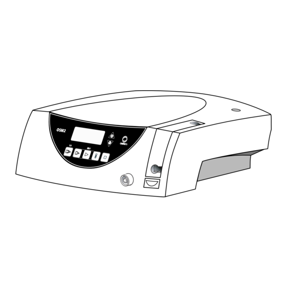
5. Description of front panel Program buttons Display Pump arm Stand holder OPEN Pump arm Motor connection socket... -
Page 12: Description Of Rear Panel
6. Description of rear panel Stand holder Connecting socket Power switch for foot control ON / OFF Power socket Fuse holder with 2 fuses REF 04014700 (250 V – 1.25A slow-blow) -
Page 13: Description Of Motor With Cable
7. Description of motor with cable The motor may not be dismantled! The motor bearings are lubricated for life. No oil lubrication or other maintenance is necessary. To prevent the instrument on the motor attachment from turning during the transmission, the locking pin supplied can be pushed into one of the two holes (see illustration). -
Page 14: Starting Operation - General
8. Starting operation – General ➊ ➍ Connect the mains cable Place the motor support and foot control. on the stand and rotate it to fix in place. ➋ ➎ Connect the motor cable. Fit the irrigation tubing Note the positioning! set. - Page 15 9. Starting operation – Foot control ORANGE Change program GREEN Pump ON / OFF YELLOW Change motor direction BLACK Start motor Operation BLACK VARIABLE or ON / OFF (Factory setting = variable) GREEN Pump ON / OFF ORANGE Program 1 to 5 YELLOW Motor forward / reverse drive...
-
Page 16: Starting Operation - Foot Control
Starting operation – Foot control Changing program The Programs 1 – 5 can be selected in ascending sequence by operating the ORANGE button. When changing from Program 5 to Program 1, a longer confirmation signal is heard. With each program change, the speed is automatically set to forward operation. Pump ON / OFF Only when the motor is stationary can the pump be switched on or off by operating the GREEN button of the foot control. - Page 17 Starting operation – Foot control To change from VARIABLE to ON / OFF Keep Program button P3 depressed throughout this procedure! ➊ Press P3 for approx. 4 seconds ➋ Keep P3 depressed and simultaneously press PLUS and MINUS ➌ Keep P3 depressed and carry out adjustment. 01 = VARIABLE (factory setting) –...
- Page 18 10. Reset factory settings Factory setting always starts with Program 1 (P1). ➊ Switch off the control unit ➋ Keep P1 depressed and simultaneously switch on the control unit ➌ Keep P1 depressed as long as on the display the adjustment “DE FAU” appears...
-
Page 19: Factory Settings
Factory settings (P1 – P5) Transmission ratio 20:1 20:1 Factory setting rpm 35 000 1 200 Adjustable range rpm 300 – 40 000 15 – 2 000 15 – 2 000 Motor direction forward forward forward Pump Factory setting Ncm max. - Page 20 11. Control unit operation – Changing the program (P1 – P5) Activate the required Program (P1 – P5) by pressing the corresponding Program button. During selection an audible signal can be heard and the Program button is illuminated. On the display the selected Program appears with the adjusted range in rpm, e.g.
-
Page 21: Control Unit Operation
Control unit operation – Changing the speed (P1 – P3, P5) Keeping PLUS / MINUS depressed activates the repeat function and the values are continuously increased / decreased. ➊ Press Program button (P1–P3, P5) ➋ Increase speed ➋ Decrease speed... - Page 22 Control unit operation – Changing the torque (P4) Adjustable range from 5 up to 50 Ncm, intermediate stage 32 Ncm. Keeping PLUS / MINUS depressed activates the repeat function and the values are continuously increased / decreased. When changing from 5 to 50 Ncm and 50 to 5 Ncm, a longer confirmation signal is heard. When the adjustable torque in the forward/reverse drive mode is reached, the motor switches off automatically.
- Page 23 Control unit operation – Changing the coolant flow (P1 – P5) Factory setting 100 %. Adjustable range 65 %, 80 % and 100 %. Depressing PLUS / MINUS the values are continuously increased / decreased. Keep Program button P2 depressed throughout this procedure! ➊...
-
Page 24: Error Messages
12. Error messages Error No. Description Remedy Electronics overheating – Switch off the equipment, allow to cool safety shutdown for at least 10 minutes, then re-start Electronics overloaded Switch off the equipment and then re-start Foot control error – Switch off the equipment, re-start, do not initializing actuate foot control when switching on Foot control error... - Page 25 13. Disinfection, Cleaning, Sterilization Follow your country-specific directives, standards and guidelines for disinfection, cleaning and sterilization. – Wear protective clothing. – Disinfect and clean the motor immediately after every treatment! – Sterilize the motor following disinfection and cleaning. – Sterilize motor with cable and motor support prior to every use. Control unit, foot control Pre-disinfection –...
-
Page 26: Disinfection, Cleaning, Sterilization
Disinfection, Cleaning, Sterilization Motor with cable Do not twist and kink the motor cable! Do not coil it too tightly! This instruction is not necessary when a sterilization cassette is utilized (optional accessory). Before disinfection and cleaning push the motor protective cover onto the motor attachment! Pre-disinfection –... - Page 27 Disinfection, Cleaning, Sterilization Sterilization and storage W&H recommends sterilization according to EN 13060, class B – Note the instructions of the unit manufacturer. – Clean before sterilizing. – Wrap motor and accessories in sterile goods packing according to EN 868-5. –...
-
Page 28: W&H Accessories
Use only original W&H accessories/spare parts 14. W&H Accessories or accessories approved by W&H 04013500 04013600 04541900 / 04542100 Sterilization cassette Transportation case Trolley white 04042600 Trolley, stainless steel 04735700 04005900 04006800 04032600 Motor support Stand Locking pin Motor protective cover... - Page 29 W&H Accessories 04720024 04785700 04308700 04014700 Motor with 1.8 m cable Foot control Step wedge for foot control Fuse 1.25A slow-blow Disposable article 04019000 04363600 04719400 Clips (5 pcs) Irrigation tubing set 2.2 m (6 pcs) Irrigation tubing set 2.2 m...
- Page 30 15. Servicing Regular checking of OSM2 and accessories Regular servicing of function and safety of the OSM2 including the accessories is necessary and should be carried out at least once every three years, unless shorter intervals are prescribed by law. The inspection must be undertaken by a qualified organization and needs to include the following procedures: –...
-
Page 31: Servicing
Servicing Motor and cable The standard ISO 11498 stipulates a durability of at least 250 sterilization cycles. In the case of the motor and cable from W&H, regular servicing is specified only after 500 sterilization cycles, or one year. Repairs If a defect occurs, always return all the equipment, due to the fact that with motor malfunctions, an inspection of the electronic controls is also necessary! Returns... - Page 32 16. Technical data OSM2 SI-923 SI-915 Supply voltage: 220 – 240 V 100 – 130 V Rated current: 0.1 – 0.8 A 0.2 – 1.6 A Permitted voltage fluctuation: ± 10 % ± 10 % Frequency: 50 – 60 Hz 50 –...
-
Page 33: Technical Data
Technical data Physical characteristics Temperature in storage: -40 °C (-40 °F) to +70 °C (+158 °F) Air humidity in storage: 8 % to 80 % (relative), non-condensing at +40 °C (+104 °F) Temperature in operation: +10 °C (+50 °F) to +40 °C (+104 °F) Air humidity in operation: 15 % to 80 % (relative), non-condensing at +40 °C (+104 °F) Recycling... -
Page 35: Letter Of Indemnity
Letter of indemnity This W&H product has been manufactured with great care by highly qualified specialists. A wide variety of tests and controls guarantee faultless operation. Please note that claims under warranty can only be validated when all the directions in the instructions for use have been followed. As manufacturer, W&H is liable for material or manufacturing defects within a warranty period of one year from the date of purchase. - Page 39 ✄ ✄ ✄ ✄...
-
Page 41: Authorized W&H Service Organizations
Authorized W&H Service organizations W&H Dentalmechanik GmbH, Ignaz-Glaser-Straße 60, A-5111 Bürmoos, Tel. +43 (0)6274 / 6236-239, Fax: +43 (0)6274 / 6236-890, E-mail: service.dept@wh.com W&H Deutschland GmbH & Co.KG, Raiffeisenstraße 4, D-83410 Laufen/Obb., Tel. +49 (0)8682 / 89 67-0, Fax +49 (0)8682 / 89 67-11, E-mail: office.de@wh.com W&H CH-AG, Aathalstrasse 84, CH-8610 Uster ZH, Tel. - Page 42 Authorized W&H Service organizations W&H (UK) LIMITED, 6 Stroud Wood Business Centre, Park Street, St. Albans, Herts AL2 2NJ, Phone: +44 (0) 1727 874990, Fax: +44 (0) 1727 874628/872254, E-mail: office.uk@wh.com W&H NORDIC AB, Tillverkarvägen 6, S-187 66 Täby, Tel. +46 (0)8 / 445 88 30, Fax +46 (0)8 / 445 88 33, E-mail: office@whnordic.se W&H ITALIA Srl, Viale A.
- Page 43 Phone: +1 / 519 / 944 67 39, Fax: +1 / 519 / 974 61 21, e-mail: admin@wnhimpex.com OSSTEM IMPLANT Co., Ltd., 8th FL, WorldMeridian Venture Center II, 426-5, Gasan-dong, Geumcheoun-gu, Seoul 153-803 Phone: +66-82-2-2125-3687, 3633, Fax: +66-82-2-2016-7001, E-mail: info@osstem.com In other countries please contact W&H Dentalmechanik GmbH, Ignaz-Glaser-Straße 60, A-5111 Bürmoos,...
- Page 44 Distribution OSSTEM IMPLANT Co., Ltd. 8th FL, WorldMeridian Venture Center II, 426-5, Gasan-dong, Geumcheon-gu, Seoul 153-803, Korea Tel. +66-82-2-2125-3687, 3633 / Fax. +66-82-2-2016-7001 / info@osstem.com / www.osstem.com Manufacturer ISO 13485, Annex II 93/42/EWG, EC 0297 W&H Dentalwerk Bürmoos GmbH Austria, A-5111 Bürmoos Postfach 1, Ignaz-Glaser-Straße 53...
Need help?
Do you have a question about the OSM 2 and is the answer not in the manual?
Questions and answers