
Subscribe to Our Youtube Channel
Summary of Contents for Keyprocessor Apollo
- Page 1 Technical manual Apollo o Internal jumper settings o Connections and options o Diagnostics o Technical data...
-
Page 2: Table Of Contents
Paasheuvelweg 20 1105BJ Amsterdam, The Netherlands www.keyprocessor.com Tel.: +31-20-4620700 This manual represents the knowledge at the above mentioned time. Keyprocessor works non- stop to improve her products. For the most recent technical information please contact your consultant or dealer. Content overview Publication ........................ - Page 3 8.8.1 Cable lenght ....................23 8.8.2 Led status ....................24 Apollo diagnostic menu ................... 25 Connecting to the Apollo console port ............25 Start diagnostic ..................25 Environment settings .................. 26 Digital IO test .................... 27 Version ..................... 28 Polyx menu ....................28 Technical specifications ...................
-
Page 4: This Document
Because the locations are unmanned, access control, alarm monitoring and environment conditions becomes very important. The Apollo can inter alia monitor the temperature, humidity and air flow but is also capable of smoke-, intrusion- and water detection in the cabinet. This monitoring is essential to increase the lifetime and reliability of the system and helps preventing malfunctioning, damage and reduces operational costs. -
Page 5: General
2 General The Apollo designed for a quick and easy installation. Nevertheless, we strongly recommend that the technicians who installing the Apollo are trained and familiar with the product. 2.1 Wiring This document assumes standard T-568 color coding of the cables... -
Page 6: Installation Start-Up
To ensure proper functioning of the Apollo, the environment of the Apollo must be compliant with certain conditions.. Caution – Install the Apollo in a protected area that is free of excessive dust and has adequate air flow. Do not operate the Apollo where the temperature and humidity is outside the specified limits Warning –... -
Page 7: Installing The Apollo Into A Rack
4 Installing the Apollo into a rack The Apollo can be provided of two mounting brackets that can be used for a standard 19 inch or metric rack installation. Caution – Ensure that the temperature in the rack does not exceed the Apollo’s maximum ambient rated temperatures. -
Page 8: Powering The Apollo
Connected the 48VDC to the green 4-way screw connector at the back of the Apollo. Apollo front: Pin nr. DC IN No function Earth connection When the 48VDC power is present and connected to the Apollo, the 12V and 24V LEDs will become active immediately. -
Page 9: Safety And Detections
5 Safety and detections The Apollo is provided of several internal protections. An event will be generated and sent to iProtect™ (or SNMP) when an internal protection is activated. The internal protections of the Apollo are: • Internal 12VDC •... -
Page 10: Internal Connector And Jumper Settings
In case the door lock doesn’t open on presenting a valid badge to the card reader and/or when an operator can’t open the door remotely anymore, the Apollo has a lock overrule function. A cable must be connected to X2 on the Apollo board, depending of the door lock. X2 - Door lock overrule... -
Page 11: Internal Supervised Output 1 / Fan
+12VDC (FAN) (default) Pin number Description + (e.g. FAN) 6.5 Internal supervised output 2 When needed, the Apollo can be provided of a 115db PIEZO Buzzer. X1 – internal supervised output 2 Pin number Description + (PIEZO Buzzer) 6.6 Supervised output voltage The voltage which is needed on the supervised outputs can be set by a jumper (12/24VDC). -
Page 12: Power Connection Controller Board
6.8 Power connection controller board X3 – Controller board Pin number Description Earth +24VDC... -
Page 13: Smart Cabinet Security: System Setup
7 Smart cabinet security: System setup Ethernet TCP/IP iProtect™ server SNMP Management server Apollo cabinet security Plug and Play; Prefab cabling Legenda Apollo configuration Apollo hardware Symbol Amount Description Sensor Ethernet Server Card reader Intrusion detector Water sensor Swing handle lock... -
Page 14: Sockets And Port Overview
7.1 Sockets and port overview The following network sockets are used when connecting an Apollo into the network, communicating with iProtect™ and a SNMP Management server: Port Description Communication Ethernet speed (HTTP) 10/100Mb Hypertext Transfer Protocol Full duplex Simple Network Management... -
Page 15: Apollo Smart Cabinet Security
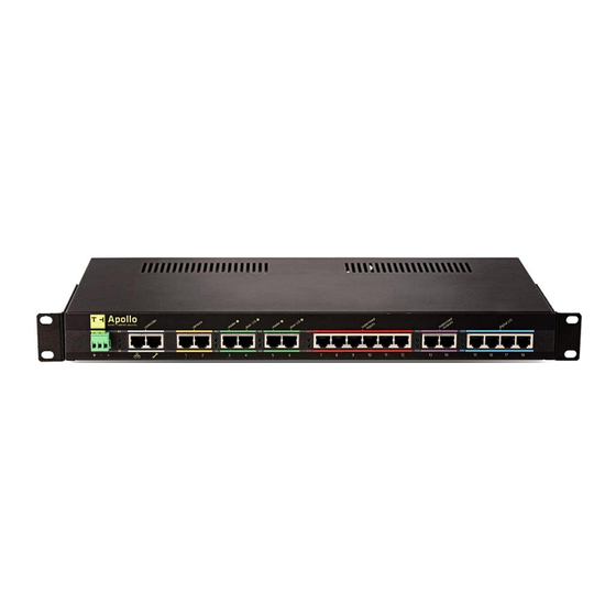
8.1 Power connector The Apollo is provided with a 3 and 4 pin removable screw connector. The functionality of the 3-pin screw connector on the front of the Apollo has been canceled with the use of 48VDC. Use the 4-pin connector connection on the rear of the Apollo. -
Page 16: Led Status
Permanent On Link with iProtect is OK 8.3 Controller: gray section The Apollo is provided with two controller ports. The left port (gray section) is a standard 10- 100Mb Ethernet port. The right port is a console (diagnostic) port. Apollo... -
Page 17: Sensors: Yellow Section
Max. 200mA White/brown Brown Reset function** ** When using an 110-230VAC power supply, you can reset the Apollo from the front side. When creating a loop between port 1 and port 2, the Apollo will restart. 8.4.1 Cable length See table below for the maximum cable length, used for this section:... -
Page 18: Reader And Door I/O: Green Section
8.5 Reader and door I/O: green section The Apollo is provided with two reader ports and two door I/O ports. Apollo front: TIA/EIA-568-B Reader 1 Comment Option Option Option Cable color White/orange Orange White/green Blue +12VDC Max. 250mA White/blue Orbit sense... -
Page 19: Cable Length
8.5.1 Cable length See table below for the maximum cable length, used for this section: Port TIA/EIA-568-B Type Maximum cable length Cable color Reader 1 RS485 Door I/O 1 Reader 2 RS485 Door I/O 2 8.5.2 Led status The reader communication and the lock output are indicated by two LEDs. Function When card reader 1 communicates, LED R1 is active When door lock 1 is active, LED L1 is active... -
Page 20: Supervised Inputs: Red Section
8.6 Supervised inputs: red section The Apollo is provided with 6 supervised inputs. These inputs can be used to connect intrusion- , or smoke detectors. The detectors will be powered by the Apollo. There is also an option to start a Walk test or to send a reset to the detectors of this section. -
Page 21: Cable Length
Output to 12VDC/GND White/brown Brown Remark! When the Apollo detects a short circuit- or an overload on this section, a messages will be send to iProtect™ 8.6.1 Cable length See table below for the maximum cable length, used for this section:... -
Page 22: Supervised Outputs: Violet Section
8.7 Supervised outputs: violet section The Apollo is provided with 2 supervised outputs. These outputs can be used to connect a siren or a flash light. The detectors will be powered by the Apollo. Apollo front: Port Pin-out TIA/EIA-568-B Supervised I/O... -
Page 23: Digital I/O: Blue Section
8.8 Digital I/O: blue section The Apollo is provided of 8 digital I/Os. The detectors (e.g. water detector) will be powered by the Apollo. Apollo front: Port Pin-out TIA/EIA-568-B Digital Comment Comment 12VDC 24VDC Cable color Polyfuse Polyfuse White/orange 500mA... -
Page 24: Led Status
8.8.2 Led status The voltage on the digital inputs are indicated by two LEDs. Function When 12VDC is present, LED 12V will be active. When there is an overload or short circuit, the LED will be deactivated When 24VDC is present, LED 24V will be active. When there is an overload or short circuit, the LED will be deactivated... -
Page 25: Apollo Diagnostic Menu
There are many different programs, like Teraterm, which can emulate a VT100 terminal on a PC. Using a simple laptop, diagnostics can be logged in via the serial port in the Apollo. Connect your PC for example to port “Console”... -
Page 26: Environment Settings
--- Environment settings --- Enter new environment setting : > ip=192.168.1.195 OK : <IP=192.168.1.195> Hit any key to continue... Note: to activate these settings reboot the system. Use option (r) and do not restart the Apollo by discharging the voltage. -
Page 27: Digital Io Test
Port 15-18: the status of the 7 inputs are displayed. The outputs can be switched using 1-8 • Voltage: The internal and external voltages are displayed • Temp: The board temperature of the Apollo is displayed • Fuse: The statuses of the fuses are displayed. Pass=ok Fail=Overload or short circuit... -
Page 28: Version
Board power device: 2; External Powered Polyx Diags version 3.0.3 uClinux version 3.3.0-uc0)(gcc version 4.4.1 (Sourcery G++ Lite 4.4-216) ) Built version: Keyprocessor/apollo Version 4.0 -- Tue Jun 3 12:09:59 CEST 2014 Sourcery G++ Lite 4.4-216) md5 fs : 7f4916973d05a4856b4faf9905151c00 md5 kernel: 181c322dc6a15ffb3c79ebdcfbc262ca Polyx version: 04.00.11... -
Page 29: Technical Specifications
Technical specifications Housing Description: 19 inch, 1HE metal housing Measurements: 482,6mm x 43.66 x 225.0 (W x H x D) Weight 3,5Kg Controller Processor Coldfire 5208, 32 bits, 166 MHZ, 159 MFLOPS Memory 32 MByte DDR ram Flash 16 MByte flash Operating system: uCLinux Ethernet:... - Page 30 Certifications CE compliant EMC (electromagnetic EN 55022 (2010) + AC (2011), compatibility): class B EN 61000-3-2 (2006) + A1 (2009) + A2 (2009) EN 61000-3-3:2008 Immunity: EN 55024:2010 Low Voltage (Product safety): EN 60950-1 (2006) + A11 (2009) + A1 (2010) + A12 (2011) Hardware Digital output...
-
Page 31: Output Load De-Rating Curve
10.1 Output load de-rating curve... -
Page 32: Technical Drawings
Technical drawings Drawing number Description 72000400 571-1013 Temperature and Humidity sensor 72000401 571-5001 Water sensor 72000402 571-2001 Sirius Card reader I30 72000403 571-3040 Bosch ISC-BDL2-W12G dualtech motion detector 72000404 571-3016 Smoke detector 72000405 571-4010 Controlled relay, with 230Vac presence check 72000406 571-3020 Viper GLX supervised shock sensor 72000407...
Need help?
Do you have a question about the Apollo and is the answer not in the manual?
Questions and answers