Table of Contents
Advertisement
ALL phases of this installation must comply with NATIONAL, STATE AND LOCAL CODES
IMPORTANT - This Document is customer property and is to remain with this unit.
Operation
Maintenance
Electronic Air Cleaner
Furnace Only Models
TFE145A9FR0
TFE175A9FR0
TFE210A9FR0
TFE245A9FR0
Please return to service information pack upon completion of work.
Air Handler Only Models
TFE215A1AH0, A9AH0
TFE235A1AH0, A9AH0
TFE260A1AH0, A9AH0
Contents
Location
Side Mount
Bottom Mount
Sequence Of Operation
Maintenance
Power Supply
To reduce the risk of electric shock, this equipment has a
grounding type plug that has a third (grounding) pin. This
plug will only fit into a grounding type power outlet. If the
plug does not fit into the outlet, contact a qualified person-
nel to install the proper outlet. Do not alter the plug in any
way.
WARNING
!
This information is for use by individuals having adequate
backgrounds of electrical and mechanical experience. Any
attempt to repair a central air conditioning product may
result in personal injury and/or property damage. The
manufacturer or seller cannot be responsible for the
interpretation of this information, nor can it assume any
liability in connection with its use.
18-HE17D7-4
2
2
3
3
4
5
5
5
6
6
6
6
6
7
7
8
Advertisement
Table of Contents

Subscribe to Our Youtube Channel
Related Manuals for American Standard TFE145A9FR0


Summary of Contents for American Standard TFE145A9FR0
- Page 1 18-HE17D7-4 Installation Operation Maintenance Electronic Air Cleaner Furnace Only Models Air Handler Only Models TFE145A9FR0 TFE215A1AH0, A9AH0 TFE175A9FR0 TFE235A1AH0, A9AH0 TFE210A9FR0 TFE260A1AH0, A9AH0 TFE245A9FR0 ALL phases of this installation must comply with NATIONAL, STATE AND LOCAL CODES IMPORTANT — This Document is customer property and is to remain with this unit.
-
Page 2: Installation
Side Mounting (Furnace Only) Bottom Return All row of holes for attaching ductwork. Figure 2. Mounting Location of Air Cleaner Pub. No. 18-HE17D7-4 © 2004 American Standard Inc. All Rights Reserved... -
Page 3: Side Mount
Installer’s Guide Discharge Air Side- Use inner Double Mounting mounting holes Entering Air Side- Holes On Flange Single Row of for Side Mounting Holes Installation On Flange Air Flow Install gasket material 1 Inch toward inner edge. Pre-Filter Cut to length required. Guides Open Position... -
Page 4: He17D7
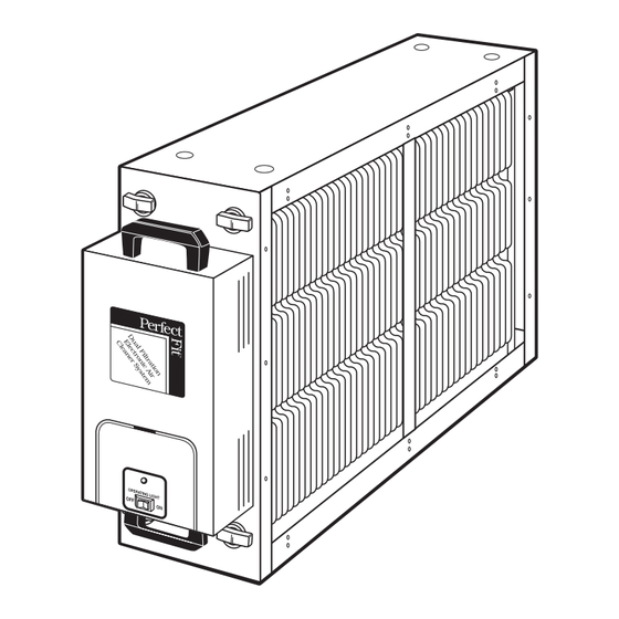
Installer’s Guide ELECTRICAL Use outer mounting holes The air cleaner unit has an air flow sensor installed. There- for Bottom fore, control wiring is not required. Installation FURNACE & AIR HANDLER - 120 VAC models These models require a 3 prong, grounded, 120 VAC outlet with a minimum circuit protection of 15 amps. -
Page 5: Ozone Reduction
Installer’s Guide When the blower stops, the green light will turn OFF. Voltage OZONE REDUCTION FEATURE at power pack cell contact and air cleaner cells is removed. All electronic air cleaners produce a small quantity of ozone that is within established limits. Some customers may notice an odor MAINTENANCE especially at high altitudes, low air flow rates or temporarily after For maximum efficiency the air cleaner cells and pre-filter should... -
Page 6: Cleaning
Installer’s Guide In some cases the green light will remain OFF during this initial FUSE REPLACEMENT activation of the air cleaner. This would indicate that the cell(s) The fuse is located in the fuse holder inside the power pack are not completely dry. The green light should turn ON once the next to the female power plug. -
Page 7: Troubleshooting
Installer’s Guide TROUBLESHOOTING SERVICE INDICATION SERVICE CHECKS 1. Power is not being supplied to the air cleaner. Blower A. Check that power switch is "ON " light OFF Green operating B. Check that the power cord is connected to the outlet and the power door. C. -
Page 8: Power Unit Removal And Replacement
Tab on power tray must be on outside of flange on cover Figure 13. Assembling Power Tray and Cover American Standard Inc. 6200 Troup Highway Tyler, TX 75707 Since the manufacturer has a policy of continuous product and product data improvement, it reserves the right...
Need help?
Do you have a question about the TFE145A9FR0 and is the answer not in the manual?
Questions and answers