Table of Contents
Advertisement
Quick Links
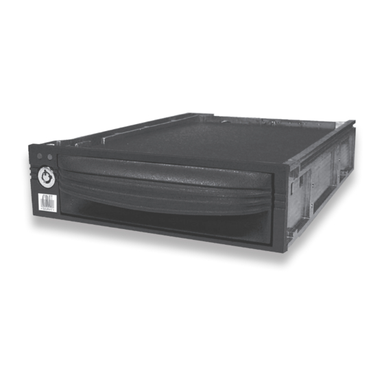
DataPort 10 SAS/SATA Install Guide
The DataPort 10 SAS/SATA provides high performance removable
storage in a compact enclosure designed to fit most desktop and
mini-tower 5.25" bays. Rugged all aluminum construction provides
superior heat dissipation needed by 15K RPM 3.5" SAS or SATA
Hard Disk Drives. The interconnect is warranted for 30K inser-
tions and 6Gb/sec full duplex operation which delivers up to 1200
MB/sec for certain applications. The DP 10 SAS/SATA frame can
support either a DP 10 SATA Carrier or the DP 10 SAS carrier when
connected to a SAS Host Bus Adapter. This feature allows data
migration from SATA systems to SAS Workstations or Servers.
Package Contents
1 - DataPort frame assembly
1 - DataPort carrier assembly
1 - Metal cover
5 - #6-32 x 1/4 flat head screws for drive mounting
4 - M3 x 5 pan head screws for frame installation
2 - Keys for lock
Mounting the Frame in the Computer
1. Turn off the computer and disconnect its power cord from the
electrical outlet. Before working on your computer, wait one
minute for any residual energy to dissipate. Remove the cover
of the computer. Determine the 5.25" half-height bay where
you plan to mount the DataPort frame assembly. Remove any
filler plates that may be present.
2. To direct mount the frame assembly.
Slide the frame into the 5.25" bay of the PC case. Using the
screws provided, secure the frame assembly to the PC case
using the frame's side or bottom mount holes.
3. To rail mount the frame assembly.
If the drive bay requires mounting rails, install one on each
side of the frame. The mounting rails should come with your
computer system.
4. Locate a SAS or SATA data cable and connect it to the data
connector on the frame. To support SAS drives the DataPort 10
SAS/SATA must be connected to a SAS host bus adapter.
Rugged, Reliable, Mobile, Secure
5. Locate an available 15-pin SAS/SATA power cable from the
computer power supply and plug it into the power connector
on the frame.
The frame installation is now completed.
Mounting a Hard Drive in the Carrier
1. The metal cover for DataPort 10 is secured by a screw.
Remove the screw and slide the top cover off the DataPort 10
carrier.
2. Slide the hard drive in from the front of the carrier and connect
it to the carrier board. If the hard drive does not fit, remove the
screw holding the circuit board in the carrier. Place the hard
drive in the carrier, then connect the circuit board to the hard
drive. Secure the circuit board with the screw and then secure
the hard drive with the provided screws.
3. Attach the Temperature Control Cooling Sensor (TCCS) to the
top of the hard drive with an adhesive strip. After the drive
has been installed, replace the top cover and secure it with the
provided metal screw.
4. Insert the carrier into the frame assembly. Ensure that the lock
of the DataPort is in the "open" (vertical) position. Position
the carrier on the guide rails, and then slide the carrier into
the frame. Using thumb pressure, fully seat the
frame and lock the unit with the key lock.
1-800-260-9800
carrier in the
www.CRU-DataPort.com
TM
Advertisement
Table of Contents

Related Manuals for CRU Dataport DataPort 10


Summary of Contents for CRU Dataport DataPort 10
- Page 1 4 - M3 x 5 pan head screws for frame installation 2 - Keys for lock 1. The metal cover for DataPort 10 is secured by a screw. Remove the screw and slide the top cover off the DataPort 10 Mounting the Frame in the Computer carrier.
-
Page 2: Limitation Of Liability
Fan Failure Alarm The fan failure alarm function is a standard feature on the DataPort 10. If the cooling fan should fail, an alarm will beep and the green LED on the upper left corner of the DataPort will flash indicating fan failure. Removal of the jumper on JP6 will silence the audible alarm on the frame.
Need help?
Do you have a question about the DataPort 10 and is the answer not in the manual?
Questions and answers