Advertisement
Quick Links
TECHNICAL DATA
Name producer:
Device:
Description:
Rated voltage AC:
Operating voltage AC:
Rated voltage DC:
Operating voltage DC:
Consumption RX:
Consumption TX:
Battery:
Current fault relay:
Current alarm relay:
Operating temperature:
Transmission power:
Operating frequency:
Frequency channel 1:
Frequency channel 2:
Range type 0600:
Range type 1200:
Range type 1800:
12
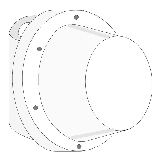
EXPLORER II
Outdoor Microwave Barrier
~
18V
~
~
16V
...24V
12V
9V
...15V
60mA
110mA
12V
, 2.1Ah
500mA
500mA
-25°C...+55°C
5mW
9.9GHz - pulse 50%
5.5KHz
7.8KHz
60m
120m
180m
Outdoor Microwave Barrier - EXPLORER II
EXPLORER II
EXPLORER II
EXPLORER II
EXPLORER II
EXPLORER II
OUTDOOR
OUTDOOR
OUTDOOR
OUTDOOR
OUTDOOR
MICROWA A A A A VE
MICROW
MICROW
MICROW
MICROW
VE
VE
VE
VE
BARRIER
BARRIER
BARRIER
BARRIER
BARRIER
INSTRUCTIONS
INSTRUCTIONS
INSTRUCTIONS
INSTRUCTIONS
INSTRUCTIONS
FOR USE
FOR USE
FOR USE
FOR USE
FOR USE
Version:
2.1
Update:
October 1998
Language:
English
Advertisement

Related Manuals for Tecnoalarm EXPLORER II


Summary of Contents for Tecnoalarm EXPLORER II
- Page 1 Frequency channel 2: 7.8KHz Range type 0600: Range type 1200: 120m Range type 1800: 180m INSTRUCTIONS INSTRUCTIONS INSTRUCTIONS INSTRUCTIONS INSTRUCTIONS FOR USE FOR USE FOR USE FOR USE FOR USE Version: Update: October 1998 Language: English Outdoor Microwave Barrier - EXPLORER II...
- Page 2 10. ANTIDISMANTLING DESCRIPTION The barrier EXPLORER II is equipped with an antidismantling function. Any EXPLORER II is a outdoor microwave barrier of extremely high reliability. attempt at dismantling provokes the opening of the tamper contact. It houses up-to-date circuit technology in an aluminium casing which is...
- Page 3 TX3 should not exceed 60°. V ATTENTION W 2.3 ANGLE POSITION EXPLORER II barriers can be powered by 18V AC or 13.8V DC. To ensure total coverage with two POWER SUPPLY 18V AC beams crossing, it is essential to Fig.
- Page 4 + type 1200: distance A = 8m + type 1800: distance A = 10m EXPLORER II is equipped with a test section which controls the correct functioning of the electronic board. The stand-by input of the receiver board has to be connected to the negative stand-by terminal of the control panel.
-
Page 5: Led Functions
COMPATIBILITY WITH PREVIOUS VERSIONS OF EXPLORER Consider that replacing a barrier of the previous EXPLORER EXPLORER II version by the new one (EXPLORER II) the Channel 1 transmission frequency has to be adjusted Channel 2 Channel 1 according to the following table:... - Page 6 As soon as adjustment has been completed, connect the automatic gain control by removing the jumper J2 (fig. 7). After approximately 10 seconds the barrier is ready for integration and sensivity adjustment. Fig. 10 EXPLORER II - Outdoor Microwave Barrier Outdoor Microwave Barrier - EXPLORER II...
Need help?
Do you have a question about the EXPLORER II and is the answer not in the manual?
Questions and answers