Table of Contents
Advertisement
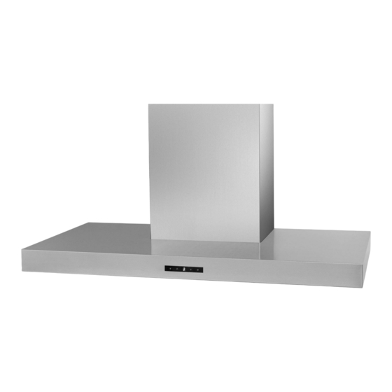
Model:
EAGLE
SERVICE
Manual
RANGE HOOD
CONTENTS
• Safety precautions
• Distance from the hob
• Technical specifications
• Technical data
• Parts supplied
• Non-return valve - parts supplied
• Aluminium panel / charcoal filter
• Installation
• Control drawing
• Touch control
• Bulbs
• Transformer
• Power board
• Electrical assembly
• Motor
• Condenser
• Wiring diagram
• Exploded view
• Spare parts list
• Troubleshooting
Advertisement
Table of Contents

Related Manuals for Tecnowind EAGLE


Summary of Contents for Tecnowind EAGLE
- Page 1 Model: EAGLE SERVICE Manual RANGE HOOD CONTENTS • Safety precautions • Distance from the hob • Technical specifications • Technical data • Parts supplied • Non-return valve - parts supplied • Aluminium panel / charcoal filter • Installation • Control drawing •...
-
Page 3: Table Of Contents
SUMMARY Safety precautions..................................4 Distance from the hob.................................7 Technical specifications.................................8 Technical data....................................9 Parts supplied ..................................10 Non-return valve - parts supplied .............................11 Aluminium panel / charcoal filter ............................12 7.1 replacing the aluminum panel 7.2 replacing the charcoal filter Installation..............................13 8.1 fixing the appliance to a wall 8.2 fixing the decorative telescopic flue 8.3 installing the charcoal filters and aluminum panels Control drawing..................................19... -
Page 4: Safety Precautions
Safety precautions cals when cleaning. Before connecting the model to the electricity network: This appliance conforms to the European Directive - Control the data plate (positioned inside the appliance) EC/2002/96, Waste Electrical and Electronic Equip- to ascertain that the voltage and power correspond to ment (WEEE). - Page 5 Safety precautions • We recommend that the cooker hood is switched on detergent. before any food is cooked. We also recommend that the appliance is left running for 15 minutes after the food is cooked, in order to thoroughly eliminate all CAUTION! contaminated air.
- Page 6 Safety precautions WARNING ! • Take care when the cooker hood is operating simultaneously with an open fireplace or burner that depend on the air in the environment and are supplied by other than electrical energy, as the cooker hood removes the air from the environment which a burner or fireplace need for combustion.
-
Page 7: Distance From The Hob
Distance from the hob Ø 265 mm • The minimum distance between the support surfaces of the cooking pots on the cooker top and the lowest part of the cooker hood must be at least 650 mm. If a connection tube composed of two parts is used, the upper part must be placed outside the lower part. Do not connect the cooker hood exhaust to the same conductor used to circulate hot air or for evacuating fumes from other appliances generated by other than an electrical source. -
Page 8: Technical Specifications
Technical specifications DUCTS CONTROLS ALUMINIUM PANELS LIGHT MODEL EAGLE Size 600-900 mm Finish St.steel A430 Motor Extracting power (m³/h) Voltage 220-240V ~ 50/60Hz Motor power consumption 1 x 130 W Product certification CE - NEMKO Product class II Type model TYPE TOP.. -
Page 9: Technical Data
Technical data motor power consumption 130 W Noise Level Noise Level Suction Pressure Speed (sound pressure) (sound power) (m³/h) (Pa) - 9 -... -
Page 10: Parts Supplied
Parts supplied CHIMNEY BRACKET NON RETURN VALVE AIR DEVIATOR 2 CHARCOAL FILTERS MOUNTING SCREWS TYPE INSERT 3,2x13 Pz 2 self-tapping screw 3,5x6 Pz 2 self-tapping screw - 10 -... -
Page 11: Non-Return Valve Parts Supplied
Non-return valve parts supplied The non-return valve is recommended when the ap- pliance is installed in the extracting version, to prevent cold air blowing back in from outside. The valve is made up of two parts which must be fixed to the air outlet flange on the motor assembly If the appliance is installed in the filtering version, the non-return valve is not necessary. -
Page 12: Aluminium Panel Charcoal Filter
Aluminium panel Charcoal filter Replacing the aluminium panel (a) 7.1 The metal filters and/or aluminium panel are also dishwasher safe. If the filters are made using aluminium, or if an aluminium panel is used, after a few washes the colour may change. This does not mean they have to be replaced. -
Page 13: Installation
Installation CAUTION! Wear gloves during the installation of the product otherwise injury at fingers could happen by sharp edges. Fixing the appliance to a wall 8.1 Before starting to fix the hood, disconnect the anti-grease filter for easier appliance handing. Before this operation, perform the following steps: Phase 1 Phase 1... - Page 14 Installation Phase 3 Phase 3 - Drill the holes A respecting the distances indicated. Fix the appli- ance to the wall and align it in horizontal position to the wall units. Phase 4 Phase 4 - When the appliance has been adjusted, definitely fix the hood using the screws A.
-
Page 15: Fixing The Decorative Telescopic Flue 8.2
Installation Fixing the decorative telescopic flue 8.2 Phase 1 Phase 1 - Arrange the electrical power supply within the dimensions of the decorative flue. If your appliance is to be installed in the duct- ing version or in the version with external motor, prepare the air exhaust opening. - Page 16 Installation Phase 3 Phase 3 - Take the air deviator D and make two holes as shown in the pho- tographs. Ø 6 - Secure the duct fixing bracket to the air deviator D as shown in the photograph. Phase 4 Phase 4 - Carry out final fixing of the air deflector D to the wall with a fixing screw as shown in the photograph.
- Page 17 Installation Phase 5 Phase 5 - Connect the flexible pipe (not supplied) to the deviator D. - Fix the flexible pipe onto the connector flange G. Phase 6 Phase 6 - Take care not to scratch the duct; wear gloves when removing the protective film.
-
Page 18: Installing The Charcoal Filters And Aluminum Panels 8.3
Installation Installing the charcoal filters and aluminum panels 8.3 Phase 1 Phase 1 - Take the active charcoal filters and position them in their hou- sings. Phase 2 Phase 2 - Take the aluminum panels and position them in their housings. - 18 -... -
Page 19: Control Drawing
Control drawing Configuration 9.1 A = on/off lights switch B = on/off cooker hood switch C = indicates the motor speed level selected D = switches on the cooker hood. Increases the motor speed E = timer - 19 -... -
Page 20: Technical Drawing Of Control Board 9.2
Control drawing Technical drawing of control board 9.2 - 20 -... -
Page 21: Touch Control
Touch Control Before carring out any kind of maintenance work, disconnect the appliance from the domestic electrical supply. Replacing the touch control 10.1 Phase 1 Phase 1 - Disconnect the aluminium panels. Phase 2 Phase 2 - Unscrew the screws as shown in the picture. Phase 3 Phase 3 - Take away the control support. - Page 22 Touch Control Phase 5 Phase 5 - Take away the control. Phase 6 Phase 6 - Unscrew the two screws as shown in the picture. Phase 7 Phase 7 - Replace the touch control. - 22 -...
-
Page 23: Bulbs
Bulbs Before carring out any kind of maintenance work, disconnect the appliance from the domestic electrical supply. Replacing the halogen bulbs 11.1 Phase 1 - To replace the halogen bulbs B, remove the glass cover C using a screw driver in the slots provided. Replace the bulbs with new ones of the same type. -
Page 24: Replacing The Halogen Bulbs Socket 11.2
Bulbs Replacing the halogen bulbs socket 11.2 Phase 1 Phase 1 - Disconnect the aluminium panels. Phase 2 Phase 2 - Unscrew the screws as shown in the pictures - 24 -... - Page 25 Bulbs Phase 3 Phase 3 - Disconnect the two fast connector. Phase 4 Phase 4 - Push the halogen bulb socket downwards and replace the bulbs socket. CAUTION! Be careful because the lamp holder metal could be damaged by pressure. - 25 -...
-
Page 26: Transformer
Transformer Before carring out any kind of maintenance work, disconnect the appliance from the domestic electrical supply. Replacing the Transformer 12.1 Before proceeding with replacement of the transformer, the fol- lowing steps must be carried out: - lift up the lower duct A - secure the lower duct adequately with adhesive tape B to the upper duct. - Page 27 Transformer Phase 1 Phase 1 - Unscrew the 4 screws as shown in the picture. Phase 2 Phase 2 - Unscrew the 4 screws as shown in the picture and disconnect the cables. - 27 -...
- Page 28 Transformer Phase 3 Phase 3 - Unscrew the 2 screws. Now you can replace the transformer. - 28 -...
-
Page 29: Power Board
Power board Before carring out any kind of maintenance work, disconnect the appliance from the domestic electrical supply. Replacing the power board 13.1 Before proceeding with replacement of the power board, the fol- lowing steps must be carried out: - lift up the lower duct A - secure the lower duct adequately with adhesive tape B to the upper duct. - Page 30 Power board Phase 1 Phase 1 - Unscrew the 5 screws as shown in the picture Phase 2 Phase 2 - Disconnect the flat cable and the electrical pins. Now you can replace the power board. ATTENTION! during the reassembling phases be carefull because there is only one correct way to connect the flat cable.
-
Page 31: Electrical Assembly
Electrical Assembly - 31 -... -
Page 32: Motor
Motor Before carring out any kind of maintenance work, disconnect the appliance from the domestic electrical supply. Replacing the motor 15.1 Before proceeding with replacement of the motor, the following steps must be carried out: - Remove the 2 srews B fixing the upper decorative duct A to the wall fixing bracket C. - Page 33 Motor Phase 1 Phase 1 - Unscrew the 2 screws as shown in the picture. And disconnect the cables. Phase 2 Phase 2 - Unscrew the 7 screws as shown in the picture, remove the motor and place it on a solid surface. - Cut the tie.
- Page 34 Motor Phase 3 Phase 3 - Unscrew the 2 screws. Phase 4 Phase 4 - Open the connector housing and disconnect the connector. Be careful while you carry out this operation. Hold the motor firmly. Phase 5 Phase 5 - Remove the screws fixing the motor to the bracket and remove the bracket from the motor.
- Page 35 Motor - 35 -...
- Page 36 Motor Phase 7 Phase 7 - Separate the RIGHT impeller housing from the LEFT Phase 8 Phase 8 - Remove the plugs from the motor support. Phase 9 Phase 9 - Remove the screws which secure the motor to the impeller hou- sing.
-
Page 37: Condenser
Condenser Before carring out any kind of maintenance work, disconnect the appliance from the domestic electrical supply. Replacing the condenser 16.1 Before proceeding with replacement of the condenser, the fol- lowing steps must be carried out: - Remove the 2 srews B fixing the upper decorative duct A to the wall fixing bracket C. - Page 38 Condenser Phase 1 Phase 1 - Remove the motor following the steps indicated in the previous paragraph. Phase 2 Phase 2 - Unscrew the tree screws as shown in the pictures. - 38 -...
- Page 39 Condenser Phase 3 Phase 3 - Remove the plastic protection and disconnect the condenser. Note! This condenser is not polarized. - 39 -...
-
Page 40: Wiring Diagram
Wiring diagram - 40 -... -
Page 41: Exploded View
Exploded view Model: EAGLE Tav.154.09 HDC6C55TX - HDC9C55TX 10.10 - EAGLE_TOU_JS - 41 -... -
Page 42: Spare Parts List
Spare parts list Model: EAGLE 60 DESCRIPTION CUST CODE POSITION ALUMINUM PANEL CHIMNEY CONVEYOR FAN WHEEL MOTOR BODY CONTROL POWER CIRCUIT MOTOR GROUP SUPPORT CONDENSER BODY FOR TANGENTIAL MOTOR TRANSFORMER HALOGEN LAMP CHIMNEY BRACKET AIR DEVIATOR Model: EAGLE 90 DESCRIPTION... -
Page 43: Troubleshooting
Troubleshooting ATTENTION! 1. The appliance has been manufactured as a class II therefore no earth cable is necessary. 2. Before carrying out any kind of maintenance job, disconnect the appliance from the domestic network sup- ply. 3. Assembly and electrical connections must be carried out by specialized personnel. Electrical Malfunction SYMPTOM CAUSE... - Page 44 3LIS0034...
Need help?
Do you have a question about the EAGLE and is the answer not in the manual?
Questions and answers