Advertisement
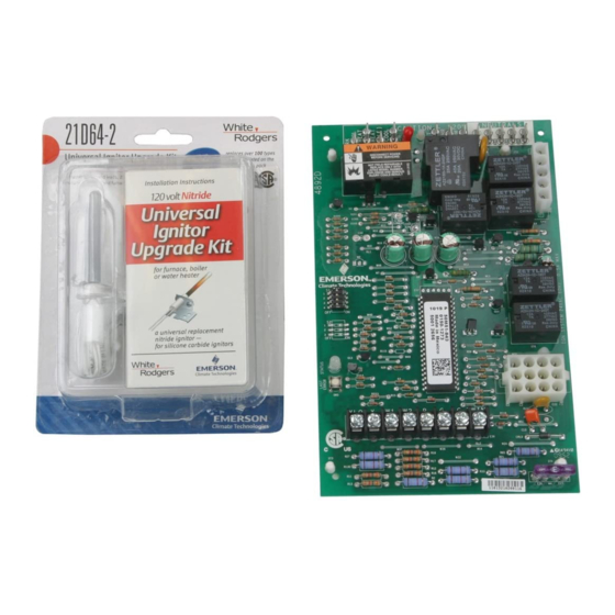
UNIVERSAL
REPLACEMENT
21M51U-843 Kit
Includes:
• Module
• HotRod
Ignitor Kit
21M51U-843 UNIVERSAL INTEGRATED HSI
FURNACE CONTROL KIT
Replaces White-Rodgers 50M51-242 and 50M61-XXX's Two-Stage
HSI Systems with 80V or 120V Ignitors
FEATURES
• 120 VAC 3-speed PSC (Permanent Split Capacitor) circulator output, two-speed
inducer output, two-stage gas valve output.
• Pushbutton fault history retrieval.
• Furnace status LED – tri-color (green, red and amber).
• Heat fan off delay (dipswitch selectable), fan on delay for cooling.
• Auto second stage delay (dipswitch selectable).
• 120 VAC humidifier output/120 VAC electronic air cleaner output.
SPECIFICATIONS
Electrical Rating:
Input Voltage. . . . . . . . . . . . . . . . . . . . 24 VAC, 60 Hz (Class II transformer required)
Nom. Input Current @ 24 VAC . . . . . . 530 mA + MV
Relay Load Ratings:
Gas Valve Relays . . . . . . . . . . . . . . . . 1.5 amps @ 24 VAC, 60 Hz
Inducer Relays . . . . . . . . . . . . . . . . . . 2.2 FLA – 3.5 LRA @ 120 VAC
Circulator Relays . . . . . . . . . . . . . . . . 14.5 FLA – 25.0 LRA @ 120 VAC
Humidifier Load . . . . . . . . . . . . . . . . . 1.0 amp max. @ 120 VAC
Electronic Air Cleaner Load . . . . . . . . 1.0 amp max. @ 120 VAC
Ignitor Relay . . . . . . . . . . . . . . . . . . . . 4.0 amps max. @ 132 VAC, 60 Hz
Flame Current Requirements:
Minimum current to insure flame detection
Maximum current for non-detection . . 0.1 µa DC*
Maximum allowable leakage resistance 100 M ohms
*Measured with a DC microameter in the flame probe lead
Operating Temperature Range . . . . . . -40
Humidity Range . . . . . . . . . . . . . . . . . 5% to 93% relative humidity (non-condensing)
Flame Failure Response Time . . . . . . 2.0 sec. max. @ 60Hz
?
TECHNICAL HELP
Wiring Diagram/Operation . . . . . . . . . . . . . . See pages 179–180
PAGES
179–180
Model
Number
Pre-Purge
21M51U-843
15
CROSS REFERENCE
21M51U-843 Replaces:
18M3401
20300001
20300003
21M51U-843
46M9901
50M51-242
50M51-495
50M61-120
50M61-288
50M61-289
www.white-rodgers.com
INTEGRATED 3-SPEED (PSC)
HSI FURNACE CONTROL
0.3 µa DC*
to 175
o
Heat
Ignitor
Delay to
Warm-Up Retries
Fan ON
17
2
45
90/120/150/180
50M61-495
50M61-843
83L9301
CNT03077
CNT6424
D344301P01
PCBBF120S
PCBBF125
X13650839010
TWO-STAGE
F (-40 to 80
C)
o
o
Cool
Cool
Automatic
Heat Delay
Delay to
Delay to
to Fan OFF
Fan ON
Fan OFF
5
60
60 minutes
Reset
Time
45
Advertisement
Table of Contents

Related Manuals for White Rodgers 21M51U-843


Summary of Contents for White Rodgers 21M51U-843
- Page 1 TWO-STAGE UNIVERSAL INTEGRATED 3-SPEED (PSC) REPLACEMENT HSI FURNACE CONTROL 21M51U-843 UNIVERSAL INTEGRATED HSI FURNACE CONTROL KIT Replaces White-Rodgers 50M51-242 and 50M61-XXX's Two-Stage HSI Systems with 80V or 120V Ignitors FEATURES • 120 VAC 3-speed PSC (Permanent Split Capacitor) circulator output, two-speed inducer output, two-stage gas valve output. • Pushbutton fault history retrieval.
- Page 2 INTEGRATED 21M51U-843 WIRING FURNACE CONTROLS AND CONFIGURATION 50M51-843 TYPICAL WIRING DIAGRAM NEUTRAL (LINE) (LINE) 120 VAC 24 VAC CLASS II TRANSFORMER 24 VAC 50M51-843 COOL PARK HEAT LO HEAT HI CIRCU- LATOR LINE BLOWER XFMR IND HI INDUCER IGNITOR IND LO...
- Page 3 21M51U-843 INTEGRATED DIAGNOSTIC TABLE FURNACE CONTROLS DIAGNOSTIC TABLE Green Amber Red LED Flash Flash Flash Error/Condition Comments/Troubleshooting Flame sensed when no flame should Verify the gas valve is operating and shutting down properly. Flame in burner be present assemble should extinguish promptly at the end of the cycle. Check orifices and gas pressure. Pressure switch stuck closed/ inducer error Pressure switch stuck closed. Check switch function, verify inducer is turning off. 1st-stage pressure switch stuck open/inducer Check pressure switch function and tubing. Verify inducer is turning on the pulling error sufficient vacuum to engage switch.
Need help?
Do you have a question about the 21M51U-843 and is the answer not in the manual?
Questions and answers